Table of Contents
Advertisement
Quick Links
This manual serves the following
ComNet Model Numbers:
FDW1000M/C
FDW1000M/R
FDW1000S/C
FDW1000S/R
EXP101/C
EXP101/R
EXP100/C
EXP100/R
INSTALLATION AND OPERATION MANUAL
FDW1000 / EXP101
OPTICAL WIEGAND, MAGSTRIPE & F/2F DATA
EXTENDER AND EXPANSION MODULE
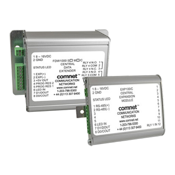
The ComNet FDW1000 Series and EXP101 Series of transceivers makes it possible to
install card readers farther from the access control panel by providing a long-range
fiber optic connection between the door or gate readers and most manufacturers'
access control panels. The series includes both a remote (door/gate) device and a
central (access control panel) device. The FDW1000 devices are compatible with the
EXP101 expansion modules that allow up to seven additional readers to share the
optical link created by the FDW1000/C (central) and FDW1000/R (remote) devices.
INS_FDW1000_EXP101 01/06/2020
Advertisement
Table of Contents

Subscribe to Our Youtube Channel
Related Manuals for Comnet FDW1000 Series


Summary of Contents for Comnet FDW1000 Series
- Page 1 OPTICAL WIEGAND, MAGSTRIPE & F/2F DATA EXTENDER AND EXPANSION MODULE The ComNet FDW1000 Series and EXP101 Series of transceivers makes it possible to This manual serves the following install card readers farther from the access control panel by providing a long-range...
-
Page 2: Table Of Contents
INSTALLATION AND OPERATION MANUAL FDW1000 / EXP101 Contents General Information – FDW1000 and EXP101 Series Device description Items in this series Specifications Power Inputs and outputs Contact closure (relay) channels Preparation Tools Before beginning Configuring Devices Configuring an FDW1000 – current version – (rev .3xx range) 7 Configuring an EXP101 –... -
Page 3: General Information - Fdw1000 And Exp101 Series
General Information – FDW1000 and EXP101 Series Device description The ComNet FDW1000 Series and EXP101 Series of transceivers makes it possible to install card readers farther from the access control panel by providing a long-range fiber optic con- nection between the door or gate readers and most manufacturers’ access control panels. The series includes both a remote (door/gate) device and a central (access control panel) device. -
Page 4: Specifications
INSTALLATION AND OPERATION MANUAL FDW1000 / EXP101 Specifications The following specifications apply to all of the items in this series Power • operating voltage range = DC 8 to 12 V, • power consumption < 6 W each • hardened power supply item number PS-AMR5-12 as needed Inputs and outputs Data •... -
Page 5: Preparation
INSTALLATION AND OPERATION MANUAL FDW1000 / EXP101 Preparation Tools • #1 tip Phillips head screwdriver to remove metal covers • small flat blade screwdriver to set the DIP switches Before beginning • determine the communications format for each reader; » Wiegand with data words that are at least 8 bits (most readers), or; »... -
Page 6: Configuring Devices
INSTALLATION AND OPERATION MANUAL FDW1000 / EXP101 Configuring Devices The FDW1000, EXP100, and EXP101 series of devices have undergone hardware and firmware revisions over time. Older revisions of FDW1000 and EXP100 may not be backward compatible with newer revisions. The revision designation is written by hand on each circuit board near the DIP switch package. -
Page 7: Configuring An Fdw1000 - Current Version - (Rev .3Xx Range)
INSTALLATION AND OPERATION MANUAL FDW1000 / EXP101 Configuring an FDW1000 – current version – (rev .3xx range) Initialization • Do not apply power to the FDW1000. Remove all fiber and signal connections. Remove the metal housing to expose the DIP switches. •... - Page 8 INSTALLATION AND OPERATION MANUAL FDW1000 / EXP101 Programming • Remove power from the FDW1000. • Turn all DIP switches OFF. • Continue to set Central / Remote (Switch 3), Supervision Relay Mode (Switch 4), Pull-Up Resistor Mode (Switch 5), and number of EXP101 pairs (Switches 6, 7, and 8) using the following table: DIP Switch Number DIP Switch Setting 1 –...
-
Page 9: Configuring An Exp101 - Current Version - (Rev .4Xx Range)
INSTALLATION AND OPERATION MANUAL FDW1000 / EXP101 Configuring an EXP101 – current version – (rev .4xx range) • Do not apply power to the EXP101. Remove all copper and signal connections. Remove the metal housing to expose the DIP switches. •... -
Page 10: Configuring An Fdw1000/C - Old Version - (Rev .2Xx Range)
INSTALLATION AND OPERATION MANUAL FDW1000 / EXP101 Configuring an FDW1000/C – old version – (rev .2xx range) Initialization • Do not apply power to the FDW1000/C. Remove all fiber and signal connections. Remove the metal housing to expose the DIP switches. •... - Page 11 INSTALLATION AND OPERATION MANUAL FDW1000 / EXP101 Programming • Remove power from the FDW1000/C. • Turn all DIP switches OFF. • Using DIP Switches 6, 7, and 8, set the communications format using the following table: Communications Format DIP Switch 6 DIP Switch 7 DIP Switch 8 not used during programming...
-
Page 12: Configuring An Fdw1000/R - Old Version - (Rev .2Xx Range)
INSTALLATION AND OPERATION MANUAL FDW1000 / EXP101 Configuring an FDW1000/R – old version – (rev .2xx range) Initialization • Do not apply power to the FDW1000/R. Remove all fiber and signal connections. Remove the metal housing to expose the DIP switches. •... - Page 13 INSTALLATION AND OPERATION MANUAL FDW1000 / EXP101 Programming • Remove power from the FDW1000/R. • Turn all DIP switches OFF. • Using DIP Switches 6, 7, and 8, set the communications format using the following table: Communications Format DIP Switch 6 DIP Switch 7 DIP Switch 8 not used during programming...
-
Page 14: Configuring An Exp100 - Old Version - (Rev .3Xx Range)
INSTALLATION AND OPERATION MANUAL FDW1000 / EXP101 Configuring an EXP100 – old version – (rev .3xx range) Initialization • Do not apply power to the EXP100. Remove all copper and signal connections. Remove the metal housing to expose the DIP switches. •... -
Page 15: Wiring And Wiring Examples
INSTALLATION AND OPERATION MANUAL FDW1000 / EXP101 Wiring and Wiring Examples Recommendations for new wire installation Power PVC - Belden 8461 - 18 AWG 1 pair, 25 feet max. Plenum - Belden 82740 - 18 AWG 1 pair, 25 feet max. Wiegand / LED PVC - Belden 9942 or 8777 - 22 AWG 3 pair shielded, 250 feet max. -
Page 16: Typical Wiring Diagrams
INSTALLATION AND OPERATION MANUAL FDW1000 / EXP101 Typical wiring diagrams The following diagrams show some typical wiring examples. For simplicity, each diagram shows only the connections that are relavent to the diagram’s purpose. Wiring common grounds TECH SUPPORT: 1.888.678.9427 / +44 (0)203 630 1653 INS_FDW1000_EXP101 01/06/2020 PAGE 16... - Page 17 INSTALLATION AND OPERATION MANUAL FDW1000 / EXP101 2-wire RS-485 bus wiring for EXP101 expansion modules TECH SUPPORT: 1.888.678.9427 / +44 (0)203 630 1653 INS_FDW1000_EXP101 01/06/2020 PAGE 17...
- Page 18 INSTALLATION AND OPERATION MANUAL FDW1000 / EXP101 Door strike follows dry contact closure, one reader TECH SUPPORT: 1.888.678.9427 / +44 (0)203 630 1653 INS_FDW1000_EXP101 01/06/2020 PAGE 18...
- Page 19 INSTALLATION AND OPERATION MANUAL FDW1000 / EXP101 Door strike follows LED, one reader TECH SUPPORT: 1.888.678.9427 / +44 (0)203 630 1653 INS_FDW1000_EXP101 01/06/2020 PAGE 19...
- Page 20 INSTALLATION AND OPERATION MANUAL FDW1000 / EXP101 Door strike follows dry contact closure, two readers TECH SUPPORT: 1.888.678.9427 / +44 (0)203 630 1653 INS_FDW1000_EXP101 01/06/2020 PAGE 20...
- Page 21 INSTALLATION AND OPERATION MANUAL FDW1000 / EXP101 Door strike follows LED, two readers TECH SUPPORT: 1.888.678.9427 / +44 (0)203 630 1653 INS_FDW1000_EXP101 01/06/2020 PAGE 21...
-
Page 22: References
INSTALLATION AND OPERATION MANUAL FDW1000 / EXP101 References LED status FDW1000 • During initialization: • A solid green STATUS LED on power up indicates that the unit has accepted the settings and that it is ready to be programmed. • After successful initialization and programming: •... -
Page 23: Dimensions
INSTALLATION AND OPERATION MANUAL FDW1000 / EXP101 Dimensions TECH SUPPORT: 1.888.678.9427 / +44 (0)203 630 1653 INS_FDW1000_EXP101 01/06/2020 PAGE 23... -
Page 24: Autocad Drawings
INSTALLATION AND OPERATION MANUAL FDW1000 / EXP101 AutoCAD drawings TECH SUPPORT: 1.888.678.9427 / +44 (0)203 630 1653 INS_FDW1000_EXP101 01/06/2020 PAGE 24... -
Page 25: Dip Switch Maps
INSTALLATION AND OPERATION MANUAL FDW1000 / EXP101 DIP switch maps Current FDW1000s (.3xx Revision Designations) and Current EXP101s (.4xx Revision Designations) Only Initialization Data Interface Select not used Wiegand Wiegand No Filter DIP Switches 6, Strobed Rising (MR5) Strobed Rising (Dorado 644) 7, and 8 set the Strobed Rising (Mag-Tek) data interface. - Page 26 INSTALLATION AND OPERATION MANUAL FDW1000 / EXP101 EXP101 Programming Polling Address Select not used Address 1 Address 2 Address 3 Address 4 DIP Switches 6, Address 5 7, and 8 set the Address 6 polling address. Address 7 Data Interface Select DIP Switches 3, not used 4, and 5 set the...
- Page 27 SUITE 4 - 2 TURNBERRY PARK ROAD | GILDERSOME | MORLEY | LEEDS, UK LS27 7LE T: +44 (0)203 630 1652 | F: +44 (0)113 253 7462 | INFO-EUROPE@COMNET.NET © 2020 Communications Networks Corporation. All Rights Reserved. “ComNet” and the “ComNet Logo” are registered trademarks of Communication Networks, LLC. INS_FDW1000_EXP101 01/06/2020...
Need help?
Do you have a question about the FDW1000 Series and is the answer not in the manual?
Questions and answers