Table of Contents
Advertisement
O p e r a t i o n s /
Ma i n t e n a n c e
I mp o r t a n t
I n f o r ma t i o n
F i l e i n y o u r
m a i n t e n a n c e
r e c o r d s
Ma n u a l
Me d i c a l
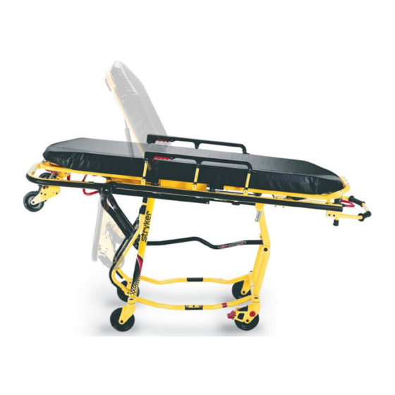
Mo d e l 6 0 9 2R u g g e d
E Z - P R O R 4
F o r p a r t so r t e c h n i c a l
a s s i s t a n c ec a l l
8 0 03 2 70 7 7 0( o p t i o n2 )
®
Advertisement
Table of Contents

Related Manuals for Stryker Rugged EZ-PRO R4 6092


Summary of Contents for Stryker Rugged EZ-PRO R4 6092
- Page 1 O p e r a t i o n s / Me d i c a l Ma i n t e n a n c e Ma n u a l Mo d e l 6 0 9 2R u g g e d ®...
-
Page 3: Table Of Contents
Table of Contents Introduction Specifications ................Warning / Caution / Note Definition . - Page 4 Table of Contents Assembly Drawings and Parts Lists Cot Assembly ..............47−51 Release Handle Assembly .
-
Page 5: Introduction
! Height measured from bottom of mattress at seat section to ground level. @ Cot is weighed without mattress and restraints. # Height limit kit is recommended for ambulance deck heights less than 30 inches (67 cm) − Stryker part number 6092−202−010. Stryker reserves the right to change specifications without notice. -
Page 6: Warning / Caution / Note Definition
Introduction WARNING / CAUTION / NOTE DEFINITION The words WARNING, CAUTION and NOTE carry special meanings and should be carefully reviewed. WARNING Alerts the reader about a situation, which if not avoided, could result in death or serious injury. It may also describe potential serious adverse reactions and safety hazards. -
Page 7: Warranty
Î Î Î Î Î Î Î Î Î Î Î Î Î Î Î Î Î Î Î Î Î Î Î Î Î Î Î Î Î Î Î Î Î Î One (1) year parts and labor. Under this option, Stryker EMS warrants to the original Î... -
Page 8: Warranty
AGED SHIPMENTS UNLESS SUCH DAMAGE IS NOTED ON THE DELIVERY RE- CEIPT AT THE TIME OF RECEIPT. Upon prompt notification, Stryker will file a freight Î Î Î Î Î Î Î Î Î Î Î Î Î Î Î Î Î Î Î Î Î Î Î Î Î Î Î Î Î Î Î Î Î Î... -
Page 9: Safety Precautions
Summary of Safety Precautions The following is a list of safety precautions that must be observed when operating or servicing this unit. The precautions are repeated throughout the manual, where applicable. Carefully read this list before using or servicing the unit. WARNING S Improper usage of the Cot can cause injury to the patient or operator and/or damage to... - Page 10 S Improper maintenance can cause injury to the patient or operator and/or damage to the unit. Maintain the cot as described in this manual. Use only Stryker approved parts and maintenance procedures. Using unapproved parts and procedures could cause unpredictable operation, damage to the cot and/or injury and will void the product warranty.
-
Page 11: Setup Procedures
S Is there an approved crash−stable fastener (Stryker part number 6370/6374/6377/6378/6379 or 6371/6375 − not included) installed in the vehicle? S Is there an approved vehicle safety hook (Stryker part number 6060−036−017, 6060−036−018 or 6092−036−018) installed in the vehicle? The patient compartment of the vehicle in which the Cot will be used must have: S A smooth rear edge for cot loading. -
Page 12: Component Identification
Foot End Height Adjustment Release Handle Base Frame Transport Wheels Wheel Lock (Optional) Transport Wheels Figure 2 − EZ−PROr R4 Long Safety Hook Short Safety Hook Stryker part number Stryker part number 6060−036−018 6060−036−017 J Safety Hook Stryker part number 6092−036−018... - Page 13 Figure 4 − Ambulance Deck Height CAUTION Height limit kit is recommended for ambulance deck heights less than 30 inches (76 cm) − Stryker part number 6092−202−010. Installation of the safety hook should be done by a certified mechanic familiar with ambulance construction.
- Page 14 To avoid injury, verify the safety bar has engaged the safety hook before removing the cot from the patient compartment. Note: Stryker recommends that, prior to installation, the certified mechanic plan the placement of the safety hook in the rear of the vehicle.
- Page 15 Vehicle Safety Hook Installation Positioning and Installing the Safety Hook (Continued) 4. Mark the position of the safety hook on the patient compartment floor. The safety hook should be installed as close as possible to the rear of the vehicle while allowing the vehicle doors to close and checking that the load wheels always remain on the patient compartment floor (i.e.
-
Page 16: Cot Positions
Cot Positions Position 1 − Folded Position − Use for patient Position 4 − Intermediate Height Position transfer and transporting in an ambulance. Use for patient transfer/cot rolling. Position 5 − Loading Position Use for patient transfer/cot rolling, folding or loading the cot. Position 2 −... -
Page 17: Cot User Tips
Cot User Tips Disengaging the auxiliary lock The auxiliary lock must always be disengaged to lower the cot from the load position or to load the cot into the ambulance. It is located at the foot end of the cot on patient’s left side. Push the lock lever towards the head end to disengage the auxiliary lock. -
Page 18: Using Restraint Straps
Cot Operation Using Restraint Straps WARNING Always use all restraint straps to secure the patient on the cot. An unrestrained or partially restrained patient may fall from the cot and be injured. Always secure the patient on the cot with all the re- straint straps. -
Page 19: Using Restraint Straps
Cot Operation Using Restraint Straps (Continued) Figure 11 − Buckling the Restraints Figure 12 − Lengthening the Safety Restraints Figure 13 − Tightening the Safety Restraint When the cot is put into service, the restraints are opened and placed to either side of the cot until the patient is positioned on the cot mattress. -
Page 20: Pedi−Matet Attachment Instructions
Pedi−Matet Infant Restraint System Attachment Instructions Refer to the Pedi−Matet users manual for the manufacturer’s recommendations for the use, operation and care of the Pedi−Matet Infant Restraint System. Securing the Pedi−Matet to the cot 1. Remove any restraints already attached to the cot. 2. - Page 21 These are general instructions for installation of the Pedi−Matet. Safe and proper use of the Pedi−Matet is solely at the discretion of the user. Stryker recommends all users be trained on the proper use of the Pedi−Matet before using it in an actual situation.
-
Page 22: Auxiliary Lock
Cot Operation Guidelines for Operation S Use the Cot only as described in this manual. S Read and understand all labels and instructions on the cot before using the cot. S Use a minimum of two operators to manipulate the cot. (If additional assistance is required, see page 31 for a reference chart). -
Page 23: Transferring The Patient To The Cot
Cot Operation TRANSFERRING THE PATIENT TO THE 1. Roll the cot to the patient. 2. Place the cot beside the patient and raise/lower the cot to the patient’s level. 3. Lower the siderails and open the restraint straps. 4. Transfer the patient to the cot using ac- cepted EMS procedures. -
Page 24: Changing Cot Height
Cot Operation CHANGING COT HEIGHT WARNING Loading, unloading and changing the position of the cot requires a minimum of two trained operators working together. The operator(s) must be able to lift the total weight of the patient, cot and any other items on the cot. - Page 25 Cot Operation CHANGING COT HEIGHT (CONTINUED) Lowering the Cot from the Load Position to an Intermediate Transport Position: 1. Two operators firmly grasp the litter frame at oppo- site ends with their palms facing up (Figure 23). 2. The foot end operator unlocks the auxiliary lock. 3.
-
Page 26: Folding And Unfolding An Empty Cot
Cot Operation CHANGING COT HEIGHT (CONTINUED) Changing Between the Loading and the Folded Position with One Operator and an Empty Cot When a cot is empty, one trained operator can fold the cot or put it into the loading position. Changing From the Loading to the Folded Position: 1. -
Page 27: Operating The Wheel Lock
Cot Operation OPERATING THE OPTIONAL WHEEL LOCK Figure 30 − Optional Wheel Lock 1. To activate the optional wheel lock, press fully down on the pedal (A) until it stops. 2. To release the optional wheel lock, depress the upper face of the wheel lock pedal with your foot or lift up with your toe under the pedal. -
Page 28: Adjusting The Wheel Locking Force
Cot Operation ADJUSTING THE WHEEL LOCKING FORCE MINIMUM MAXIMUM Figure 31 − Optional Wheel Lock Force Adjustment 1. To adjust the wheel locking force, remove the hex socket screw from the center of the lock pedal. The wheel lock is initially assembled with the pedal set at the minimum locking force. The marker on the pedal (item A) is aligned with the marker on the octagonal sleeve (item B). -
Page 29: Loading The Cot Into A Vehicle
Cot Operation LOADING THE COT INTO A VEHICLE (CONTINUED) 1. Place the cot in the loading position (see page 15). 2. Roll the cot to the open door of the patient compartment, approaching the vehicle squarely. 3. Fold the vehicle bumper to the raised position (if available). -
Page 30: Unloading The Cot From A Vehicle
Cot Operation UNLOADING THE COT FROM A VEHICLE WARNING Loading, unloading and changing the position of the cot requires a minimum of two trained operators working together. The operator(s) must be able to lift the total weight of the patient, cot and any other items on the cot. -
Page 31: Unloading The Cot From A Vehicle
Cot Operation UNLOADING THE COT FROM A VEHICLE (CONTINUED) Figure 35 − Locking Pin Properly Engaged Figure 36 − Locking Pin Not Properly Engaged... -
Page 32: Using Additional Assistance
Cot Operation USING ADDITIONAL ASSISTANCE Rolling Loading/Unloading Changing Levels Helper Helper Helper Helper Operators Helpers Operator Operator Operator Operator Operator Helper Helper Operator Helper Helper Helper Helper Helper Operator Helper Helper Operators Helper Four Helpers Operator Operator Operator Helper Operator Helper Helper Helper... -
Page 33: Adjusting The Leg Rest
Cot Operation ADJUSTING LEG REST FOOT END Figure 37 − Raising/Lowering the Leg Rest The leg rest is adjustable to allow for elevation of the patient’s legs. To raise the leg rest, lift the leg rest frame (A) as high as possible. The support bracket will engage automati- cally. -
Page 34: Operating The Backrest
Cot Operation Figure 38 − Pneumatic Backrest and Siderails OPERATING BACKREST To raise, squeeze handle (A) for pneumatic assist in lifting the backrest to the desired height. Remove your hand(s) from the handle when the desired height is achieved. To lower, squeeze handle (A) and push down on the backrest frame until the backrest has reached the de- sired height. -
Page 35: Operating The Breakaway Head Section
Cot Operation OPERATING BREAKAWAY HEAD SECTION The head end of the cot litter folds down to shorten the length of the cot (Figure 39) to allow easier maneuver- ing when space is limited in elevators, halls, etc. The breakaway head section should only be used when the cot is in positions 2−5 (see page 14). -
Page 36: Operating The Iv Pole
Cot Operation OPERATING 2−STAGE I.V. POLE Figure 42 − Storage Position Figure 43 − 2−Stage I.V. Pole 1. Lift and pivot the pole from the storage position and push down until it is locked into the receptacle (A). 2. To raise the height of the pole, turn the lock actuator (B) counterclockwise and pull up on the telescoping portion (C) of the pole to raise it to the desired height. - Page 37 Cot Operation OPERATING 3−STAGE I.V. POLE (OPTIONAL EQUIPMENT) 1. Lift and pivot the pole from the storage position and push down until it is locked into receptacle (A). 2. To raise the height of the pole, turn the lock actuator (B) counterclock- wise and pull up on the bottom telescoping portion (C) of the pole to raise it to the desired height.
-
Page 38: Cleaning
SOME CLEANING PRODUCTS ARE CORROSIVE IN NATURE AND MAY CAUSE DAMAGE TO THE PRODUCT IF USED IMPROPERLY. If the products described above are used to clean Stryker patient care equipment, measures must be taken to insure the cots are wiped with clean water and thoroughly dried follow- ing cleaning. -
Page 39: Preventive Maintenance
Improper maintenance can cause injury to the patient or operator and/or damage to the unit. Maintain the cot as described in this manual. Use only Stryker approved parts and maintenance procedures. Using unap- proved parts and procedures could cause unpredictable operation, damage to the cot and/or injury and will void the product warranty. - Page 40 If cot performance does not improve after the checklist is performed or if you are not comfortable performing the inspection, please contact a Stryker certified service technician for assistance.
- Page 41 Notes...
-
Page 42: Service Information
Service Information PNEUMATIC BACKREST ADJUSTMENT Required Tools: 1/2” Wrench 5/32” Allen Wrench Loctite 3/32” Allen Wrench 7/32” Allen Wrench 9/16” Wrench Adjustment Procedure: 1. For easier access, move the backrest to 75 degrees. NOTE Before continuing with the backrest adjustment procedure, be sure the pneumatic cylinder (item A) is com- pletely threaded into the yoke (item B) so no threads are showing on the shaft of the cylinder. -
Page 43: Foot End Release Handle Adjustment
Service Information FOOT END RELEASE HANDLE ADJUSTMENT Contact Point 2 Contact Point 1 Figure 48 − Foot End Release Components 1. Remove the bolt (G) and disconnect the link (B). 2. Lift the cot at both ends to take the weight off the base frame. Pull the foot end release handle and verify the patient left latch bar (C) is touching the foot end lever support bracket (E) at contact point 1 as shown above. -
Page 44: Auxiliary Lock Handle Adjustment
Service Information AUXILIARY LOCK HANDLE ADJUSTMENT Figure 49 − Auxiliary Lock Components 1. Remove bolt (A). 2. Pull and hold the auxiliary lock release link (B) toward the head end of the cot until the auxiliary lock lever (C) bottoms in the slot of the lever guard (D), 3. -
Page 45: C−Channel Wax Application
Figure 50 − Application of Stick Wax 1. Reach under the cot litter frame and apply the stick wax (Stryker part number 6090−700−001) to the inner surface of the black c−channel. Cover the entire surface between the oblong holes with a thin, even film of wax. -
Page 46: Lubrication
EZ−PROr R4 has been designed to operate without the need for lubrication. Tri−Flowt with TeflonR lubricant (Stryker part number 6082−199−012) may be used to maintain the smooth operation of the cot. Do not use silicone, WD−40t, or lithium grease. They could harm the moving parts of the cot. -
Page 47: Maintenance Record
Maintenance Record Date Maintenance Operation Performed... -
Page 48: Training Record
Training Record Training Date Training Method Trainee Name Basic Refresher Owner’s Manual, In−Service, Training Update Formal Class, Etc. -
Page 49: Cot Assembly
Cot Assembly Assembly part number 6092−50−12 (reference only) - Page 50 Cot Assembly Fowler Back of Fowler Foot Section Foot Section...
- Page 51 Cot Assembly Detail A Detail B Detail C DETAIL A DETAIL B DETAIL C...
- Page 52 Cot Assembly...
-
Page 53: Cot Assembly
6092−40−25 Foot Release Lower Link 6060−90−2 Serial Number Tag 4−334 H. Soc. But. Hd. Cap Scr. 6082−90−42 8” STRYKER Label 4−518 H. Soc. But. Hd. Cap Scr. 6060−90−4 Small “Rugged” Label 6090−5−46 Tie Rod 6060−90−114 “Keep Hands Clear” Label 2 11−45... -
Page 54: Release Handle Assembly
6092−40−40 Release Handle Assembly Item Part No. Part Name Qty. 6080−40−41 Release Handle Link 25−125 Semi−Tubular Rivet 6092−40−50 Side Release Handle... -
Page 55: Base Assembly
Base Assembly Assembly part number 6092−1−11 (reference only) Detail 1 Detail 2 Detail 3... - Page 56 Base Assembly DETAIL 1 DETAIL 3 DETAIL 2...
- Page 57 Base Assembly...
- Page 58 Base Assembly...
- Page 59 Base Assembly DETAIL 6 DETAIL 7 When assembling item AT bushing and item AN nylon washer, ensure the bushing DETAIL 8 is inserted completely through the nylon washer. Verify the assembly moves freely after assembling item N socket head cap screw. Dual Retaining Post Option...
-
Page 60: Base Assembly
Base Assembly Item Part No. Part Name Qty. Item Part No. Part Name Qty. 3−205 Hex Hd. Cap Screw 6091−1−32 Inner Base Spacer 4−18 Soc. Hd. Cap Screw 6092−1−33 Center Weldment 4−45 H. Soc. But. Hd. Cap Scr. 6091−1−52 Front Leg, Right 4−136 Torx Pan Hd. -
Page 61: Optional Lift Bar Assembly
6092−257−10 Optional Lift Bar Assembly Item Part No. Part Name Qty. 4−235 Hex Soc. But. Hd. Cap Screw 37−238 Hole Plug 6092−157−11 Lift Tube 6092−157−14 Bracket... -
Page 62: Wheel Assembly
6060−2−10 Wheel Assembly Item Part No. Part Name Qty. 6060−2−45 Molded Wheel 6060−2−46 Bearing Spacer 81−226 Bearing 715−1−255 Wheel Bushing... -
Page 63: Tie Rod Assembly
Tie Rod Assembly, Right & Left 6091−1−81 Left Tie Rod 6091−1−80 Right Tie Rod Item Part No. Part Name Qty. Item Part No. Part Name Qty. 6091−1−83 Tie Rod Wear Guard, Lt. 6091−1−82 Tie Rod Wear Guard, Rt. 6091−1−94 Tie Rod Tube, Lt. 6091−1−93 Tie Rod Tube, Rt. -
Page 64: Bumper Tube Assembly
6090−205−000 Bumper Tube Assembly 6091−1−85 Left Bumper Tube 6091−1−90 Right Bumper Tube Item Part No. Part Name Qty. Item Part No. Part Name Qty. 6091−1−86 Bumper Wear Guard, Lt. 6091−1−91 Bumper Wear Guard, Rt. 6091−1−95 Bumper Tube, Lt. 6091−1−96 Bumper Tube, Rt. 25−79 Dome Head Rivet 25−79... -
Page 65: Latch Bar Assembly
6091−700−115 Latch Bar Assembly Item Part No. Part Name Qty. 25−153 Semi−Tubular Rivet 6092−105−20 Latch Bar Spring Clip 6092−105−35 Latch Bar Weldment... -
Page 66: Base Lock Tube Assembly
6091−005−565 Base Lock Tube Assembly Item Part No. Part Name Qty. 8−27 Shoulder Bolt 28−177 Retaining Ring 38−450 Compression Spring 6091−205−58 Lock Pin 6090−205−59 Lock Bar Roller 6091−5−63 Lock Bar Roller Guide (page 65) Lock Tube Bearing Ass’y... -
Page 67: Lock Tube Bearing Assembly
6090−5−64 Base Lock Tube Bearing Assembly Item Part No. Part Name Qty. 6090−5−68 Lock Bar Weldment 81−4 Bronze Bushing 6090−5−70 Track Roller Assembly Item Part No. Part Name Qty. 6090−5−75 Track Roller 81−251 Track Roller Bushing... -
Page 68: Retaining Post Assembly
Cot Retaining Post Assembly 6091−204−45 Cot Retaining Post 6091−4−46 Patient Left Cot Retaining Post Item Part No. Part Name Qty. Item Part No. Part Name Qty. 6091−204−46 Retaining Post Head 6091−204−48 Retaining Post Head, Left 6091−204−47 Post Tube 6091−204−47 Post Tube 6060−4−43 Retaining Post Cap 6060−4−43... -
Page 69: Auxiliary Lock Housing Assembly
6092−6−25 Auxiliary Lock Housing Assembly Item Part No. Part Name Qty. 4−161 Hex Soc. But. Hd. Cap Screw 14−7 Nylon Washer 16−28 Fiberlock Hex Nut 38−432 Extension Spring 3001−300−99 Modified Bushing 6092−6−26 Auxiliary Lock Housing 6090−6−27 Auxiliary Lock Slide 6091−6−28 Auxiliary Lock Lever Arm 3−364 Hex Washer Hd. -
Page 70: Fowler Bracket Assembly
6092−32−10 Fowler Bracket Assembly Item Part No. Part Name Qty. 25−122 Dome Head Rivet 6092−32−11 Fowler Support Bracket 6092−32−12 Fowler Bracket Filler Panel 6092−32−13 Fowler Supt. Brkt. Mount, Rt. 6092−32−14 Fowler Supt. Brkt. Mount, Lt. - Page 71 Wheel Lock Options 6082−501−10 One Wheel Lock Option Item Part No. Part Name Qty. 6082−2−12 Caster Horn (page 70) Wheel Lock Ass’y 6082−502−10 Two Wheel Locks Option Item Part No. Part Name Qty. (page 70) Wheel Lock Ass’y...
- Page 72 6082−200−10 Adjustable Wheel Lock Assembly Item Part No. Part Name Qty. 6082−100−12 Caster Horn 6080−100−32 Spring 11−456 Washer 25−153 Semi−Tubular Rivet 6080−90−101 Warning Label 6080−200−30 Adjustable Pedal 6080−200−41 Octagonal Sleeve 4−98 Hex Soc. But. Hd. Cap Screw 16−118 Centerlock Nut...
-
Page 73: Litter Assembly
Litter Assembly Assembly part number 6092−30−11 (reference only) - Page 74 Litter Assembly DETAIL 1 DETAIL 2...
- Page 75 Litter Assembly DETAIL 3 DETAIL 4 DETAIL 5...
- Page 76 Litter Assembly DETAIL 6...
-
Page 77: Litter Assembly
Litter Assembly Item Part No. Part Name Qty. Item Part No. Part Name Qty. 4−135 Hex Soc. But. Hd. Cap Scr. 946−35−25 Liner 4−515 Pan Hd. Machine Scr. 6082−25−33 Pivot Mount Spacer 4−161 Hex Soc. But. Hd. Cap Scr. 6082−25−55 Pivot Mount 4−468 Hex Soc. -
Page 78: Siderail Assembly
6092−26−10 Folddown Siderail Assembly Item Part No. Part Name Qty. 6060−25−24 Top Rail 6060−25−29 Lock Release 6060−25−35 Pivot Bushing 6060−25−40 Spindle Pivot Stop 6060−25−41 Spindle Pivot 6060−25−43 Siderail Spindle 6060−25−47 Spindle Lock Post 6061−125−30 Lock Bar 25−131 Semi−Tubular Rivet 38−344 Compression Spring... -
Page 79: Lift Tube Assembly
6092−40−51 Litter Lift Tube Assembly Item Part No. Part Name Qty. 6080−40−11 Grip 6092−40−52 Lift Tube... - Page 80 Breakaway Head Section Assembly Assembly part number 6080−37−56 (Reference only) Spring (both sides) should be installed with lower hook opening facing foot end.
- Page 81 Breakaway Head Section Assembly Item Part No. Part Name Qty. 4−54 Button Head Cap Screw 4−163 Button Head Cap Screw 4−197 Button Head Cap Screw 4−204 Button Head Cap Screw 4−209 Button Head Cap Screw 4−231 Button Head Cap Screw 4−612 Button Head Cap Screw 16−20...
-
Page 82: Breakaway Head Assembly
Breakaway Head Section Assembly Note: Need to order Lift option (6091−156−016) to complete functional head section. Breakaway Head Assembly − Standard Components − 6080−37−10 (reference only) Item Part No. Part Name Qty. 14−67 Nylon Flat Washer 25−79 Dome Head Rivet 28−138 Retaining Ring 6080−36−25... -
Page 83: Breakaway Head Assembly
Breakaway Head Section Assembly Breakaway Head Assembly − Standard Height Option − 6082−37 (reference only) Item Part No. Part Name Qty. 6082−37−40 Center Pivot, Head Section Breakaway Head Assembly − Extended Height Option − 6082−38 (reference only) Item Part No. Part Name Qty. -
Page 84: No Iv Pole Option
6092−213−10 No IV Pole Option Item Part No. Part Name Qty. 4−97 Hex Soc. But. Hd. Cap Screw 4−163 Hex Soc. But. Hd. Cap Screw 11−65 Flat Washer 16−28 Nylock Nut 6092−30−80 Siderail Bracket... - Page 85 6092−210−10 Optional 2−Stage IV, Patient Right 6092−215−10 Optional 3−Stage IV, Patient Right PATIENT RIGHT FOOT END 6092−210−10 6092−215−10 Item Part No. Part Name Qty. Item Part No. Part Name Qty. 6080−110−35 IV Clip 6080−110−35 IV Clip (page 84) 2−Stage IV Pole, Right (page 82) 3−Stage IV Pole, Right 16−28...
- Page 86 6090−210−20 2−Stage IV Assembly, Patient Right Item Part No. Part Name Qty. 6070−90−105 Caution Label (page 89) 2−Stage IV Pole Assembly 6070−110−37 IV Pivot Pin 25−79 Dome Head Rivet 6090−90−31 Specification Label 6100−115−51 Socket Weldment...
- Page 87 6090−215−20 3−Stage IV Assembly, Patient Right Item Part No. Part Name Qty. 6070−90−105 Caution Label 6070−110−37 IV Pivot Pin 25−79 Dome Head Rivet (page 90) 3−Stage I.V. Pole Assembly 6090−90−33 Specification Label 6100−115−51 Socket Weldment...
- Page 88 6092−211−10 Optional 2−Stage IV, Patient Left 6092−216−10 Optional 3−Stage IV, Patient Left PATIENT LEFT FOOT END 6092−211−10 6092−216−10 Item Part No. Part Name Qty. Item Part No. Part Name Qty. 6080−110−35 IV Clip 6080−110−35 IV Clip (page 87) 2−Stage IV Pole, Left (page 88) 3−Stage IV Pole, Left 16−28...
- Page 89 6090−211−20 2−Stage IV Assembly, Patient Left Item Part No. Part Name Qty. 6070−90−105 Caution Label (page 89) 2−Stage IV Pole Assembly 6070−1100−37 IV Pivot Pin 25−79 Dome Head Rivet 6090−90−32 Specification Label 6100−115−51 Socket Weldment...
- Page 90 6090−216−20 3−Stage IV Assembly, Patient Left Item Part No. Part Name Qty. 6070−90−105 Caution Label 6070−110−37 IV Pivot Pin 25−79 Dome Head Rivet (page 90) 3−Stage IV Pole Assembly 6090−90−34 Specification Label 6100−115−51 Socket Weldment...
-
Page 91: Stage Iv Pole Assembly
6070−210−70 2−Stage IV Pole Assembly Item Part No. Part Name Qty. 1210−110−46 Back−Up Ring 1210−110−47 Lock Ring 1210−110−49 Molded Actuator 6070−210−51 Base Tube 6070−110−42 2nd Stage Tube 6070−110−51 2nd Stage Slide Plug 6070−110−50 Hook Weldment 26−6 Roll Pin 6070−110−12 I.V. Pole Pivot... -
Page 92: Stage Iv Pole Assembly
6070−215−70 3−Stage IV Pole Assembly Item Part No. Part Name Qty. 1210−110−46 Back−Up Ring 1210−110−47 Lock Ring 1210−110−49 Molded Actuator 6070−210−51 Base Tube 6070−110−51 2nd Stage Slide Plug 6070−110−50 Hook Weldment (page 91) 3rd Stage Assembly 6070−115−42 2nd Stage Tube 6070−115−45 Bearing Plug 26−5... -
Page 93: Rd Stage Assembly
6070−115−30 3−Stage I.V. Pole 3rd Stage Assembly Item Part No. Part Name Qty. 6070−115−141 Spring Clip 6070−115−143 3rd Stage Tube 6070−115−44 3rd Stage Slide Plug 26−4 Roll Pin 45−139 O−Ring... - Page 94 6092−212−10 Optional Dual 2−Stage IV Pole Assembly FOOT END Item Part No. Part Name Qty. 4−163 Hex Soc. But. Hd. Cap Screw 11−65 Flat Washer 16−28 Nylock Nut 6080−110−35 IV Clip (page 84) 2−Stage IV Pole, Right (page 87) 2−Stage IV Pole, Left 6092−30−80 Siderail Bracket...
- Page 95 6092−217−10 Dual 3−Stage IV Pole Assembly FOOT END Item Part No. Part Name Qty. 4−163 Hex Soc. But. Hd. Cap Screw 11−65 Flat Washer 16−28 Nylock Nut 6080−110−35 IV Clip (page 82) 3−Stage IV Pole, Right (page 88) 3−Stage IV Pole, Left 6092−30−80 Siderail Bracket...
-
Page 96: Optional Pull Handle Assembly
6092−155−20 Optional Pull Handle Assembly Item Part No. Part Name Qty. 4−136 But. Hd. Cap Screw 4−265 Hex Soc. But. Hd. Cap Screw 11−16 Flat Washer 16−14 Nylock Hex Nut 25−79 Dome Head Rivet 958−1−224 I.V. Clip 6092−155−50 Pull Handle Holder Bracket 6090−155−51 Pull Handle Retainer Clamp 6090−155−53... - Page 97 6091−300−10 Pedi−Matet Restraint Bracket Option Item Part No. Part Name Qty. 6080−32−60 Restraint Bracket 25−79 Rivet...
- Page 98 6080−140 Optional Hanging Oxygen Bottle Holder Ass’y Item Part No. Part Name Qty. 6080−140−11 Bottle Holder Hanger 6080−140−12 Oxygen Bottler Holder...
- Page 99 6092−140 Optional Foot End O2 Bottle Holder Item Part No. Part Name Qty. 6060−140−13 Strap Assembly (page 98) Bottle Holder Tray 25−79 Dome Hd. Rivet 6092−140−17 Bottle Holder 6092−90−14 Specification Label...
- Page 100 6060−140−20 Foot End O2 Bottle Holder Tray Item Part No. Part Name Qty. 11−436 Flat Washer 25−133 Rivet 37−55 37−56 Washer 946−1−155 Bumper 6060−140−15 Bottle Holder Tray...
- Page 101 6082−140 Optional Head End Oxygen Bottle Holder Item Part No. Part Name Qty. 4−197 Hex Soc. But. Hd. Cap Screw 16−102 Nylock Hex Nut 25−79 Blind Rivet (page 100) Tray Assembly 6082−140−43 Strap Assembly 6082−140−44 Fowler Handle Guard...
- Page 102 6082−140−40 Head End O2 Bottle Holder Tray Item Part No. Part Name Qty. 4−455 But. Hd. Cap Screw 11−52 Washer 11−436 Washer 16−28 Hex Nut 25−99 Dome Head Rivet 25−133 Dome Head Rivet 29−3 Brass Eyelet 37−55 Black Protective Cap 37−56 Retaining Washer 946−1−155...
-
Page 103: Optional Base Storage Tray Assembly
6092−150−15 Optional Base Storage Tray Assembly Item Part No. Part Name Qty. (page 102) Base Storage Tray Ass’y 25−79 Rivet... - Page 104 6092−150−20 Storage Tray Assembly Item Part No. Part Name Qty. 37−52 Bumper 6092−250−19 Tray 6092−90−4 Label...
-
Page 105: Optional Head End Storage Tray
6092−128 Optional Head End Storage Tray Item Part No. Part Name Qty. 4−197 Button Hd. Cap Screw 16−102 Nylock Nut (page 104) Tray... - Page 106 Head End Storage Tray Assembly part number 6092−128−20 (reference only) Item Part No. Part Name Qty. 6092−128−80 Tray 6082−128−19 Adhesive Loop Pile 6081−91−47 Caution Label...
- Page 107 6100−044 Head Extension Option Kit Item Part No. Part Name Qty. 6100−41−30 Head Extension Pillow (page 106) Head Extension Assembly...
- Page 108 Head Extension Assembly Assembly part number 6100−44−12 (reference only) Item Part No. Part Name Qty. 6100−44−10 Bracket Weldment 6100−44−7 Support 6100−44−11 Extension Tube 6100−44−8 Pillow Support 6100−44−5 Insert 28−76 Clip 6100−44−6 Spacer 16−28 Nylock Nut 4−161 Button Head Cap Screw 4−232 Button Head Cap Screw 6372−10−16...
-
Page 109: Backrest Pouch Option
6500−130−000 Backrest Pouch Option Item Part No. Part Name Qty. 6500−001−241 Backrest Storage Pouch... -
Page 110: Restraint Strap Package
6082−260−10 Restraint Strap Package SHOULDER HARNESS ASSEMBLY REQUIRED 1 STRAP REQUIRED 2 STRAPS REQUIRED Item Part No. Part Name Qty. 6060−260−45 Four Point Harness 6060−160−44 Lap Belt 6082−160−51 Plastic Cap 6082−260−046 Chest Restraint Strap 37” 37” Fully Extended Fully Extended... - Page 111 6092−128−12 Optional Head End Storage Pouch 28 1/2” FRONT OF POUCH 20 1/4” 20” 6082−160−52 Optional Accessory Strap 27 1/2” 27 1/2” Fully Extended Fully Extended...
-
Page 112: Defibrillator Platform
6092−170 Optional Defibrillator Platform Item Part No. Part Name Qty. 6082−170−50 Defib U−Foot Weldment 6080−170−20 Defib Latch Strap Assembly 4−234 Button Head Cap Screw 11−355 Washer 16−102 Nylock Nut 26−172 Slotted Spring Pin 6092−90−22 Label, ’Specification and Warning’ 1... - Page 113 The parts and accessories listed on this page are all currently available for purchase. Some of the parts identi- fied on the assembly drawings pages in this manual may not be individually available for purchase. Please call Stryker Customer Service at 1−800−327−0770 for availability and pricing. ITEM...
- Page 114 Quick Reference Replacement Parts List Permanent I.V. Pole Kit, 2−Stage, Right ........6092−210−010 Permanent I.V.
- Page 116 European Representative Stryker EMEA RA/QA Director Stryker France ZAC Satolas Green Pusignan Av. De Satolas Green 69881 MEYZIEU Cedex France 3800 E. Centre Ave., Portage, MI 49002 (800) 327−0770 www.stryker.com JH 08/2007 6092−009−001 REV A...
Need help?
Do you have a question about the Rugged EZ-PRO R4 6092 and is the answer not in the manual?
Questions and answers