Table of Contents
Advertisement
Quick Links
OPERATIONS MANUAL
The GO BED
TM
ELECTRIC ACUTE CARE BED
Product Number: FL17E
Product Number for the United States: 2500
TECHNICAL ASSISTANCE AND PARTS
1 800 428-5025 (Service in English in Canada)
1 800 361-2040 (Service in French in Canada)
1 800 327-0770 (In United States)
E-mail (Canada):
service@bertec.strykercorp.com
December 2000
Manufactured by Stryker Bertec Medical Inc
72-0171 R1.0
Printed in Canada
Advertisement
Table of Contents

Related Manuals for Stryker GO BED FL17E


Summary of Contents for Stryker GO BED FL17E
- Page 1 TECHNICAL ASSISTANCE AND PARTS 1 800 428-5025 (Service in English in Canada) 1 800 361-2040 (Service in French in Canada) 1 800 327-0770 (In United States) E-mail (Canada): service@bertec.strykercorp.com December 2000 Manufactured by Stryker Bertec Medical Inc 72-0171 R1.0 Printed in Canada...
-
Page 3: Table Of Contents
TABLE OF CONTENTS 1. INTRODUCTION............................5 1.1 BED SPECIFICATIONS ........................5 1.2 TECHNICAL SUPPORT ........................5 1.3 WARNING / CAUTION / NOTE DEFINITIONS ................6 1.4 SAFETY TIPS AND GUIDELINES ....................6 1.5 WARRANTY ............................ 8 Limited Warranty..........................8 To Obtain Service and/or Parts ...................... 8 Return Authorization ........................ - Page 4 3.11 EMERGENCY CRANK USAGE ....................26 Manual Operation of the Bed......................26 Stryker Bertec gives special attention to the quality of the information found in this document. Any comments on its content will be most welcomed. Please forward your remarks to our Technical Service...
-
Page 5: Introduction
200 VAC, 50-60Hz, 3.2 A 220 VAC, 50-60 Hz, 2.9 A 240 VAC, 50-60 Hz, 2.7 A * Stryker Bertec Medical affords special attention to product improvement and reserve the right to change specifications without notice. 1.2 TECHNICAL SUPPORT For questions regarding this product, contact one of the following Technical Service... -
Page 6: Warning / Caution / Note Definitions
Chapter 1 The GO BED Operations Manual 1.3 WARNING / CAUTION / NOTE DEFINITIONS The words carry special meanings and should be carefully WARNING CAUTION NOTE reviewed. The personal safety of the patient or user may be involved. Disregarding this information could result in injury to the patient or user. - Page 7 Introduction Chapter 1 • Side-rails, with or without their padded covers or nets, are not intended to serve as restraint devices to keep patient from exiting the bed. Side-rails are designed to keep a patient from inadvertently rolling off the bed. It is the responsibility of the attending medical personnel to determine the degree of restraint necessary to ensure a patient will remain safely in bed.
-
Page 8: Warranty
(see section 1.2) or your local representative. To Obtain Service and/or Parts For an on-site diagnosis and/or repair of a bed malfunction by a Stryker Field Service Representative or to order replacement parts (see section 1.4, "To Order Parts" in the GO BED Maintenance Manual), simply contact Stryker Bertec Technical Service department or your local representative. -
Page 9: Bed Mattress Care
Introduction Chapter 1 Mattress Care Failure to properly clean mattress or dispose of them if defective will increase the risk of exposure to pathogenic substances which may cause injury to the patient or user. Inspection • Implement local policies to address regular care, maintenance, and cleaning of mattresses and covers. -
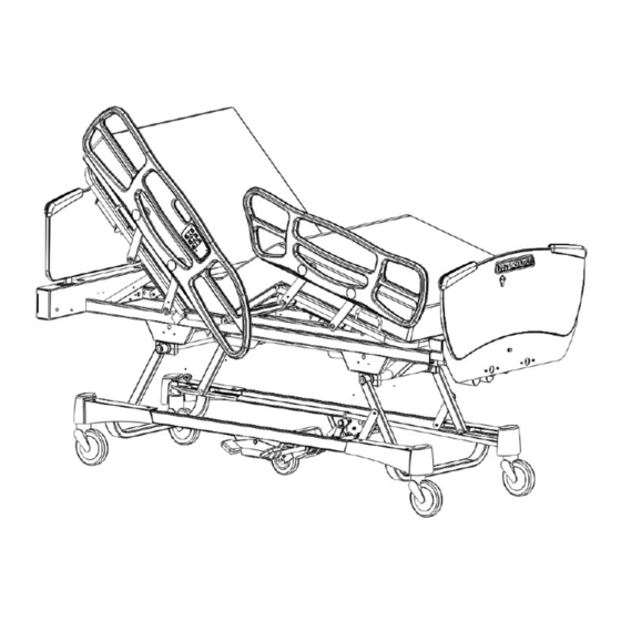
Page 10: Bed Illustration
Chapter 1 The GO BED Operations Manual 1.8 BED ILLUSTRATION (Bed may differ from illustration) SIDE RAIL INSIDE CONTROL PANEL HEAD SECTION HEAD SIDE RAIL CENTER SECTION PUSH PULL HANDLE THIGH SECTION HEAD BOARD FOOT SECTION FOOT SIDE RAIL SIDE RAIL OUTSIDE CONTROL PANEL FOOT BOARD... -
Page 11: Bed Operation Guide
Bed Operation Guide Chapter 2 2. BED OPERATION GUIDE Features qualified as "Optional Equipment" are described throughout this chapter. They are factory installed. Throughout this guide, the words "right" and "left" refer to the right and left sides of a patient lying face up on the bed. -
Page 12: Steer Pedal Operation
Chapter 2 The GO BED Operations Manual Steer Pedal Operation To engage the 5th wheel, press the green "AXIAL STEER" side of the brake/steer pedal fully down on either side of the bed. To disengage 5th wheel, press the red "TOTAL BRAKE" side of the brake/steer pedal until pedal reaches the neutral position (horizontal position). -
Page 13: Foot Prop Usage
Bed Operation Guide Chapter 2 2.5 FOOT PROP USAGE A foot prop rod, integrated to the foot section is automatically engaged when the Knee Gatch is raised. This foot prop maintains the foot section nearly horizontal as the Knee Gatch raises thus positioning the sleeping surface into the vascular position (see section 1.7, "Bed Positions"). -
Page 14: Night Light (Optional) Usage
Chapter 2 The GO BED Operations Manual 2.9 NIGHT LIGHT (OPTIONAL) USAGE The GO BED may be equipped with an optional photoelectric night light to illuminate the floor area around the bed. The night light turns on as the room lights dim. It is located on the left side of the frame at the foot end of the bed. -
Page 15: Head And Foot Boards
Bed Operation Guide Chapter 2 2.13 HEAD AND FOOT BOARDS The GO BED has socket-type bed end mountings. The head board and the foot board slide down into two mounting sockets located at each end of the bed. Both boards can be fixed permanently. -
Page 16: Side-Rail Function Guide
Chapter 2 The GO BED Operations Manual 2.14 SIDE-RAIL FUNCTION GUIDE Side-rail control panel may differ in shape depending on the type of side-rail equipping the bed. OUTER CONTROL PANEL Right side-rail Left side-rail Figure 2.13A A: Push to raise Fowler. C: Push to raise sleeping surface E: Push to raise Knee Gatch B: Push to lower Fowler. -
Page 17: Foot Board Control Panel Guide
Bed Operation Guide Chapter 2 2.15 FOOT BOARD CONTROL PANEL GUIDE SIDE RAIL BED FUNCTION LEEPING SURFACE POSITION SWITCH LOCK OUT SWITCH HEAD THIGH TRENDELENBURG CONTOUR AUTOMATIC CONTOUR SWITCH INDICATOR PICTOGRAM WHEN ON OPTIONAL Lock-out Switches (A1 to A3) These three switches enable the selective lock out of the bed functions available to patient and nursing staff through the side-rail control panels (inside and outside). -
Page 18: Hi-Lo Switches
Chapter 2 The GO BED Operations Manual Hi-Lo Switches (D1 and D2) These two switches enable adjustment of the sleeping surface height (Hi-Lo). D1: Push to raise the sleeping surface D2: Push to lower the sleeping surface. Trendelenburg Switch (E) This switch, when activated, enables both Trendelenburg positions through the Hi-Lo switches. -
Page 19: Accessories
Accessories Chapter 3 3. ACCESSORIES Features qualified as "Accessory" are described in this section of the guide. They are products, as is the GO BED, and can be ordered at the same time beds are ordered or later on. They carry a product number (P/N). -
Page 20: Pendant Control Usage
Chapter 3 The GO BED Operations Manual 3.2 PENDANT CONTROL USAGE Different models of pendant controls offering access to two or three bed functions are available as accessories with the GO BED. A clip for bed sheet is integrated on all models allowing the pendant control to be placed within patient reach. -
Page 21: Patient Helper System Usage
Accessories Chapter 3 3.3 PATIENT HELPER SYSTEM USAGE The patient helper system provides a support that enables the patient to raise himself up using arm pull. The system features a lower fixed section, an upper movable section and a trapeze. When in use, the upper movable section is centered over the patient. -
Page 22: Mattress Support Extension Usage
Chapter 3 The GO BED Operations Manual 3.4 MATTRESS SUPPORT EXTENSION USAGE A mattress support extension may be installed to extend the sleeping surface length by 8" (20 cm). Also available are 2" and 3" thick mattress extension cushions (8" long). Installing the Mattress Support Extension 1. -
Page 23: Bed Craddle Usage
Accessories Chapter 3 3.5 BED CRADDLE USAGE A bed cradle can be fitted to the GO BED to keep bedding (top sheets, etc.) from coming into contact with a patient's specific body part ( feet, chest, etc.) thus enhancing the patient comfort. Patient restraint strap locations are used to fit the bed cradle on the bed. -
Page 24: Flip Type Bed Shelf Usage
Chapter 3 The GO BED Operations Manual 3.7 FLIP TYPE BED SHELF USAGE A light weight bed shelf can be installed on the GO BED foot board to support small equipment such as a T.V. set, monitor, etc. A tether, attached to the shelf, may be used to secure objects placed on it. -
Page 25: Oxygen Bottle Holder Usage
Accessories Chapter 3 3.8 OXYGEN BOTTLE HOLDER USAGE The oxygen bottle holder, designed to fit on the foot board, allows the installation of an oxygen bottle. Possible fire hazard exists when this bed is used with oxygen administering equipment other than nasal, mask type or half bed-length tent type. -
Page 26: Chart Holder Usage
Chapter 3 The GO BED Operations Manual 3.10 CHART HOLDER USAGE The chart holder, which stores the patient's medical records, is ideal when a patient is being transferred in his bed from one unit to another. It has been designed to fit on the foot board and can hold up to legal document size (8½"...
Need help?
Do you have a question about the GO BED FL17E and is the answer not in the manual?
Questions and answers