Table of Contents
Advertisement
MAINTENANCE MANUAL
The GO BED
TM
ELECTRIC ACUTE CARE BED
Product Number: FL17E
Product Number for the United States: 2500
TECHNICAL ASSISTANCE AND PARTS
1 800 428-5025 (Service in English in Canada)
1 800 361-2040 (Service in French in Canada)
1 800 327-0770 (In United States)
E-mail (Canada):
service@bertec.strykercorp.com
December 2000
Manufactured by Stryker Bertec Medical Inc
72-0173 R1.0
Printed in Canada
Advertisement
Table of Contents

Related Manuals for Stryker The Go BED FL17E


Summary of Contents for Stryker The Go BED FL17E
- Page 1 TECHNICAL ASSISTANCE AND PARTS 1 800 428-5025 (Service in English in Canada) 1 800 361-2040 (Service in French in Canada) 1 800 327-0770 (In United States) E-mail (Canada): service@bertec.strykercorp.com December 2000 Manufactured by Stryker Bertec Medical Inc 72-0173 R1.0 Printed in Canada...
-
Page 3: Table Of Contents
TABLE OF CONTENTS 1. INTRODUCTION............................5 1.1 BED SPECIFICATIONS ........................5 1.2 TECHNICAL SUPPORT ........................5 1.3 SAFETY ............................6 Warning / Caution / Note Definition ....................6 Safety Tips and Guidelines......................6 Static Discharge Precautions......................8 1.4 WARRANTY ............................ 8 Limited Warranty.......................... - Page 4 APPENDIX B: BED POSITIONS FOR MAINTENANCE PURPOSE............64 Stryker Bertec gives special attention to the quality of the information found in this document. Any comments on its content will be most welcomed. Please forward your remarks to our Technical Service...
-
Page 5: Introduction
200 VAC, 50-60 Hz, 3.2 A 220 VAC, 50-60 Hz, 2.9 A 240 VAC, 50-60 Hz, 2.7 A * Stryker Bertec Medical affords special attention to product improvement and reserve the right to change specifications without notice 1.2 TECHNICAL SUPPORT... -
Page 6: Safety
Chapter 1 The GO BED Maintenance Manual 1.3 SAFETY Warning / Caution / Note Definition The words carry special meanings and should be carefully WARNING CAUTION NOTE reviewed. The personal safety of the patient or user may be involved. Disregarding this information could result in injury to the patient or user. - Page 7 Introduction Chapter 1 • Side-rails, with or without their padded covers or nets, are not intended to serve as restraint devices to keep patient from exiting the bed. Side-rails are designed to keep a patient from inadvertently rolling off the bed. It is the responsibility of the attending medical personnel to determine the degree of restraint necessary to ensure a patient will remain safely in bed.
-
Page 8: Static Discharge Precautions
To Require Service To obtain the service of a Stryker Field Service Representative for an on-site diagnosis and/or repair of a bed malfunction, contact the Stryker Bertec Technical Service department or your... -
Page 9: To Order Parts
• Write down the serial number, the production number (e.g. FL17-XXXX) and the bed model (manufacturer's nameplate). Make sure that the bed is indeed a Stryker Bertec bed. At first glance, beds manufactured by other companies may resemble ours. •... -
Page 10: Return Authorization
Claims will be limited in amount to the actual replacement cost. In the event that this information is not received by Stryker Bertec within the fifteen (15) days period following the delivery of the merchandise, or the damage was not noted on the delivery notice at the time of receipt, the customer will be responsible for payment of the original invoice in full. - Page 11 Introduction Chapter 1 Raise the bed to full up position and activate the Trendelenburg function (see "Trendelenburg Switch (E)", Operations Manual, page 21). Ensure that the head end lowers to the full down position. Raise the bed to the full up position and activate the reverse Trendelenburg function (see "Trendelenburg Switch (E)", Operations Manual, page 21).
-
Page 12: Bed Illustration
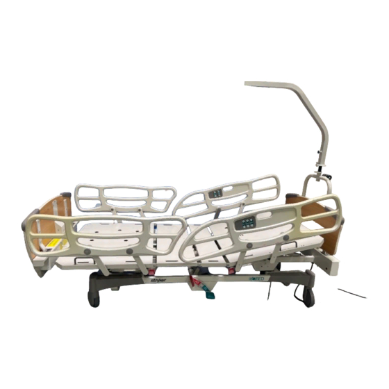
Chapter 1 The GO BED Maintenance Manual 1.6 BED ILLUSTRATION (Bed may differ from illustration) SIDE RAIL INSIDE CONTROL PANEL HEAD SECTION HEAD SIDE RAIL CENTRE SECTION PUSH PULL HANDLE THIGH SECTION HEAD BOARD FOOT SECTION FOOT SIDE RAIL SIDE RAIL OUTSIDE CONTROL PANEL FOOT BOARD... -
Page 13: Preventive Maintenance
Preventive Maintenance Chapter 2 2. PREVENTIVE MAINTENANCE This section contains a recommended spare parts list as well as cleaning instructions and a checklist to assist with the preventive maintenance and cleaning of your equipment. In the text, the words "right" and "left" refer to the right and left sides of a patient lying face up on the bed. -
Page 14: Lubrication
Listed below are the lubrication points and their recommended time interval check. When needed, lubricate these points with OG2 grease (Stryker Bertec part number M0027). The use of types of grease other than the one recommended (OG2 grease) could lead to deterioration of critical parts and to mechanism failure, resulting in injury to the patient or user and damage to the bed. -
Page 15: Lubrication Points Illustrated
Preventive Maintenance Chapter 2 Lubrication Points Illustrated LEGEND: 1 YEAR 2 YEARS 5 YEARS Figure 2.2A Figure 2.2B Figure 2.2D Figure 2.2E Figure 2.2C Figure 2.2... -
Page 16: Preventive Maintenance Program
Chapter 2 The GO BED Maintenance Manual 2.3 PREVENTIVE MAINTENANCE PROGRAM The following periodic maintenance and inspection program has been devised to ensure a long and productive life to your GO BED. Each item on the schedule should be checked and any necessary adjustment made during the preventive maintenance process. -
Page 17: Pc Board Maintenance Program
Preventive Maintenance Chapter 2 Automatic foot prop rod working properly when Knee Gatch or Auto Contour function is activated. No cracks or splits in head and foot boards Head end bumpers tightly secured to frame and working properly No rips or cracks in mattress cover Power cord not frayed No cables worn or pinched All electrical connections tight... -
Page 18: Recommended Spare Parts
Chapter 2 The GO BED Maintenance Manual Recommended Spare Parts The following is a list of recommended on hand spare parts for the GO BED. Electronic/Electrical Assembly Parts PC Board QDF14-0990 PC Board stand off pins QDF8011 Strain relief bushing QPNC0604 S.A. -
Page 19: Troubleshooting
Troubleshooting Chapter 3 3. TROUBLESHOOTING This section contains a troubleshooting chart to assist you with the diagnosis of problems with your equipment. In the text, the words "right" and "left" refer to the right and left sides of a patient lying face up on the bed. - Page 20 Chapter 3 The GO BED Maintenance Manual PROBLEM POSSIBLE CAUSES RECOMMENDED ACTION ON/OFF switch is on, the bed ON/OFF switch LED defective. Replace ON/OFF switch responds to commands but (see section 4.9). the LED power indicator does not light up. ON/OFF switch is on but the * Foot board control Check cable connection...
- Page 21 Troubleshooting Chapter 3 PROBLEM POSSIBLE CAUSES RECOMMENDED ACTION * ** PC Board dip switches Set Dip switches properly. improperly set. DIP #1 = off; DIP #2 = on; DIP #3 = off; DIP #4 = off. * ** If your bed is equipped Check CPR mechanism with the optional CPR release and both micro switch...
- Page 22 Chapter 3 The GO BED Maintenance Manual PROBLEM POSSIBLE CAUSES RECOMMENDED ACTION The micro switch cable Check cable connection improperly connected to the (see section 4.8). Refer to PC Board. Connection Diagram in Appendix A for proper connecting position. The micro switch cable running Replace micro switch from the micro switch to the cable.
- Page 23 Troubleshooting Chapter 3 PROBLEM POSSIBLE CAUSES RECOMMENDED ACTION Nurse call switch defective. Replace nurse call switch (see section 4.5). Nurse call switch cable Replace nurse call cable defective (see section 4.5) Safety side-rails jam, move Side-rail mechanisms poorly Apply grease on the side- with difficulty, do not latch in greased and/or mechanism rail plungers, plunger...
-
Page 24: Maintenance Procedures
Failure to observe this restriction can result in serious damage to material and/or severe injury to people. The use of types of grease other than the one recommended (OG2 grease, Stryker Bertec part number M0027) could lead to deterioration of critical parts and mechanism failure, resulting in injury to the patient or user and damage to the bed. -
Page 25: Head Side-Rail Assembly Replacement
Maintenance Procedures Chapter 4 5. Manually lift and fold the foot section back towards the head end of the bed (see figure 4.1 in Appendix B). 6. Remove the four bolts / lock washers (A) holding the side-rail assembly to the foot section. Apply medium strength tread locker (blue) on the bolt treads, before replacing the four bolts. - Page 26 Chapter 4 The GO BED Maintenance Manual 9. Pull on the cable to slide it out of the cable ties holding it along its path under the bed. It might be necessary to cut the cable ties to install the new nurse call cable. HEAD SECTION HEAD SIDE RAIL...
-
Page 27: Side-Rail Replacement (Rail Only)
Maintenance Procedures Chapter 4 4.2 SIDE-RAIL REPLACEMENT (RAIL ONLY) Foot Side-Rail Replacement (Rail Only) Figure 4.2 Raise the bed to the high position and lock casters. Raise side-rail needing a rail replacement. Unplug the power cord from the wall receptacle. Use a small screwdriver to remove the plastic dome caps (A) sealing the front part of the two rail shafts. -
Page 28: Membrane Replacement (Foot Board Control Panel)
Chapter 4 The GO BED Maintenance Manual 4.3 MEMBRANE REPLACEMENT (FOOT BOARD CONTROL PANEL ) The membrane comes with the control panel plate, already affixed to it. Figure 4.3 1. Raise the bed to the high position and lock casters. 2. -
Page 29: Membrane Replacement ( Side-Rail Control)
Maintenance Procedures Chapter 4 4.4 MEMBRANE REPLACEMENT ( SIDE-RAIL CONTROL) Figure 4.4 1. Raise the bed to high position and lock casters. 2. Raise the head side-rail needing a membrane replacement. 3. Unplug the power cord from the wall receptacle. 4. -
Page 30: Nurse Call System Component Replacement
Chapter 4 The GO BED Maintenance Manual 4.5 NURSE CALL SYSTEM COMPONENT REPLACEMENT TO WALL RECEPTACLE Figure 4.5 1. Raise the bed to high position and lock casters. 2. Remove the head board. 3. Remove the fourteen screws (C, fig. 4.1 B, page 24) holding the head end casing cover (E fig. - Page 31 Maintenance Procedures Chapter 4 7. Reverse the above steps to install the replacement cable. 8. Test nurse call function for proper operation before returning bed to service. End of procedure. 9. Identify the right (F, fig. 4.5, page 29) or left (G, fig. 4.5, page 29) nurse call cable wires, cut the cable tie if necessary.
-
Page 32: Foot Board Connector Replacement
Chapter 4 The GO BED Maintenance Manual 4.6 FOOT BOARD CONNECTOR REPLACEMENT Figure 4.6 1. Raise the bed to high position and lock casters. 2. Remove head board and lay on a workbench. 3. Remove the 7 screws (A) securing the support cover (B) to the inner face of the foot board and remove cover. -
Page 33: Foot End Case Connector Replacement
Maintenance Procedures Chapter 4 4.7 FOOT END CASING CONNECTOR REPLACEMENT Figure 4.7A 1. Raise the bed to high position, lock casters and remove the foot board. 2. Unplug the power cord from the wall receptacle. 3. Remove the 12 screws (A, B) holding the foot end casing cover (C) and the two IV pole holders (E) to the foot end casing (D). -
Page 34: Pc Board Replacement
Chapter 4 The GO BED Maintenance Manual 4.8 PC BOARD REPLACEMENT 1. Raise the bed to high position and lock casters. 2. Unplug the power cord from the wall receptacle. 3. Remove the foot panel. 4. Properly ground yourself (see "Static Discharge Precautions", page 8). 5. -
Page 35: On/Off Switch Replacement
Maintenance Procedures Chapter 4 4.9 ON/OFF SWITCH REPLACEMENT Refer to fig. 4.7A, page 33, for illustration of the reference points mentioned in this section. 1. Raise the bed to high position and lock casters. 2. Unplug the power cord from the wall receptacle. 3. -
Page 36: Night Light System Component Replacement
Chapter 4 The GO BED Maintenance Manual 4. Cut cable tie holding wires together. 5. Disconnect the bed power cord connector (A) from the PC Board power cord connector (B). Note the connecting position of the connectors, white wire opposite white wire, black opposite black. - Page 37 Maintenance Procedures Chapter 4 12. Remove the 12 screws (A, B, fig. 4.7A, page 32) holding the foot end casing cover (C, fig. 4.7A, page 32) and the two IV pole holders (E, fig. 4.7A, page 32) to the foot end casing. 13.
-
Page 38: 120V Auxiliary Outlet Component Replacement
Chapter 4 The GO BED Maintenance Manual 4.12 120V AUXILIARY OUTLET COMPONENT REPLACEMENT Always unplug the power cord from the wall outlet when cleaning or servicing the bed. Danger: 120V current. The following procedure aims at troubleshooting and replacing a defective part in the 120V auxiliary outlet assembly. -
Page 39: Mattress Support Section Replacement
Maintenance Procedures Chapter 4 10. Remove the screw (C) holding the duplex receptacle (D) to the housing. Loosen the screws holding the wires to the duplex receptacle. Note their connecting positions. 12. Test the duplex receptacle. - if defective, proceed with step 13 through step 15 and end procedure. - if functioning properly, go to step 16. -
Page 40: Thigh Section Replacement
Chapter 4 The GO BED Maintenance Manual 4. Unplug the power cord from the wall receptacle. 5. Manually lift and fold the foot section back towards the head end of the bed (see figure 4.1 in Appendix B). 6. Remove from the foot section the parts that will be transferred to the replacement foot section, i.e. -
Page 41: Center Section Replacement
Maintenance Procedures Chapter 4 6. If the bed is equipped with the Auto Contour option, remove the two screws (B) holding the micro switch activator (C) underneath the thigh section and save activator for the replacement thigh section. Apply grease on the activator after having replaced it back underneath the replacement thigh section. -
Page 42: Head Section Replacement
Chapter 4 The GO BED Maintenance Manual Head Section Replacement HEAD SECTION CENTRE SECTION HEAD TÊTE Figure 4.13D Bed without Optional CPR 1. Raise the bed to high position, lock casters and bring mattress support to horizontal position. 2. Remove the head board. 3. -
Page 43: Bed With Optional Cpr
Maintenance Procedures Chapter 4 HEAD SECTION Figure 4.13E 10. Remove the bolt/locknut (E) holding the upper part of the compression bar (F) to the head section and lay it down. 11. Remove the bolt/flat washers(2)/locknut (G) linking the lower part of the compression bar to the head section and remove the compression bar. - Page 44 Chapter 4 The GO BED Maintenance Manual 7. Plug the bed, bring Fowler back to horizontal position and unplug the bed. 8. Remove the Rue ring/washer/nylon washers(2)/clevis pin (G, fig. 4.14, page 44) hooking up the head actuator tube to the head section lever arms. Apply grease on the clevis pin and the nylon washers before hooking up the actuator tube to the head section.
-
Page 45: Actuator Replacement
Maintenance Procedures Chapter 4 4.14 ACTUATOR REPLACEMENT LO ACTUATOR LO ACTUATOR KNEE GATCH ACTUATOR HEAD ACTUATOR Figure 4.14 Unless otherwise stated, all reference points of each actuator replacement procedure will refer to figure 4.14 above. -
Page 46: Knee Gatch Actuator Replacement
Chapter 4 The GO BED Maintenance Manual Knee Gatch Actuator Replacement 1. Raise bed to maximum elevation, lock casters and bring mattress support to horizontal position. 2. Bring the head safety side-rails down and raise the foot safety side-rails. 3. Unplug the power cord from the wall receptacle. 4. -
Page 47: Head Actuator Replacement
Maintenance Procedures Chapter 4 Head Actuator Replacement 1. Raise bed to high position, lock casters and bring Fowler to horizontal position. 2. Raise the Knee Gatch to high position. 3. Unplug the power cord from the wall receptacle. 4. Remove the foot board. 5. -
Page 48: Hi-Lo Actuator Replacement
Chapter 4 The GO BED Maintenance Manual Hi-lo Actuator Replacement In order to preserve the adjustment of the bed lowest position when replacing a Hi-lo actuator, a special tool kit designed for that purpose must be used. To obtain this kit, contact our Service department (see section 1.2) and order part number KR0054. -
Page 49: Actuator Screw Lubrication Procedure
Maintenance Procedures Chapter 4 4.15 ACTUATOR SCREW LUBRICATION PROCEDURE The basic rule to grease the actuator screws is to extend the actuator to its maximum length so as to uncover a maximum of its screw treads. Unless otherwise stated, refer to fig. 4.14, page 45 for illustration of the reference points mentioned in this section. -
Page 50: Hi-Lo Actuator Screws
Chapter 4 The GO BED Maintenance Manual 9. Loosen the bolt (H) holding the head actuator to its bracket until the actuator can be rotated downward and removed from its location. Lay actuator on a workbench. Apply grease on the bolt, the spring washer and the inner sides of the bracket, including the pivot pin, when reassembling the actuator. -
Page 51: Cpr Mechanism Springs And/Or Damper Replacement
Maintenance Procedures Chapter 4 4.16 CPR MECHANISM SPRINGS AND/OR DAMPER REPLACEMENT When activating the CPR release, all people and equipment must be removed from the area below and around the head and foot sections of the bed or serious personal injury or damage to equipment could occur. -
Page 52: Cpr Micro Switch Replacement
Chapter 4 The GO BED Maintenance Manual 4.17 CPR MICRO SWITCH REPLACEMENT When activating the CPR release, all people and equipment must be removed from the area below and around the head and foot sections of the bed or serious personal injury or damage to equipment could occur. -
Page 53: Micro Switch Located Under The Mattress Support
Maintenance Procedures Chapter 4 Micro Switch Located Under the Mattress Support BLACK WIRE BLACK WIRE MICRO SWITCH CONNECTIONS RED WIRE BLACK WIRE Figure 4.17A Raise the bed to the high position and lock casters. Raise Knee Gatch to maximum height. Manually lift and fold the foot section back towards the head end of the bed (see figure 4.1 in Appendix B). -
Page 54: Auto Contour Micro Switch Replacement
Chapter 4 The GO BED Maintenance Manual 4.18 AUTO CONTOUR MICRO SWITCH REPLACEMENT LEFT MOBILE RAIL FOOT END Figure 4.18 Knee Gatch Micro Switch 1. Raise the bed to the high position and lock casters. 2. Unplug the power cord from the wall receptacle. 3. -
Page 55: Brake /Steer Pedal Replacement
Maintenance Procedures Chapter 4 4.19 BRAKE /STEER PEDAL REPLACEMENT Figure 4.19 1. Raise the bed to the high position, lock casters and unplug the power cord. 2. Bring pedal to horizontal position (neutral) and remove the machine screw (A) located at the end of the right or left pedal shaft. -
Page 56: 5Th Wheel Mechanism Component Replacement
Chapter 4 The GO BED Maintenance Manual 4.20 5TH WHEEL MECHANISM COMPONENT REPLACEMENT Unless otherwise stated, all reference points mentioned in the procedures contained in section 4.20 will refer to figure 4.20 below. PIED / FOOT END TH WHEEL SWING ARM ASSEMBLY Figure 4.20 5th Wheel Replacement... -
Page 57: 5Th Wheel Swing Arm Assembly Replacement
Maintenance Procedures Chapter 4 4. Remove the machine screw (A, fig. 4.19, page 54) located at the end of the right and left pedal shafts. Note that in prior versions (beds with serial number [ C01340), the GO BED is equipped with protective caps instead of machine screws. - Page 58 Chapter 4 The GO BED Maintenance Manual 6. Remove the pressure screws (B, fig. 4.19, page 54) located on the head and foot locking levers (E, fig. 4.19, page 54). 7. Remove both pedals completely. Remove the two pedal sleeves (C, fig. 4.19. page 54). Keep the four nylon washers (D, fig.
-
Page 59: Caster Replacement
Maintenance Procedures Chapter 4 4.21 CASTER REPLACEMENT Figure 4.21 1. Raise the bed enough to place under the frame at the head or foot end of the bed (depending on the caster to be changed) two jack stands adjusted to a height of 20" (see figure 4.21A in Appendix B). - Page 60 Chapter 4 The GO BED Maintenance Manual 11. Remove the bolt/washer (H) holding the caster shaft to the mounting socket (J). Before replacing the bolt, apply medium strength tread locker (blue) on its tread. 12. Support caster while pulling the locking axle (E) out its location. Note the nearly vertical position of the Rue ring hole to correctly replace the locking axle later on.
-
Page 61: Hi-Lo Lever Replacement
Maintenance Procedures Chapter 4 4.22 HI-LO LEVER REPLACEMENT TÊTE / HEAD FOOT END Figure 4.22 1. Raise the bed to the high position and lock casters. 2. Adjust mattress support depending on the Hi-lo lever to be replaced: Hi-lo lever located at the head end of the bed Raise Fowler to maximum. - Page 62 Chapter 4 The GO BED Maintenance Manual 8. Remove the four bolts/washers/locknuts/reinforcement plates (two) (E) holding the Hi-lo lever (D) and the moulded bearings (F) to the mobile frame (G). Apply grease inside the moulded bearings before replacing them. 9. Remove the Hi-lo lever from its location by rotating it horizontally on one side to disengage the nylon sliders (H) from the rails (J).
-
Page 63: Appendix A: Connection Diagram
Appendix A: Connection Diagram GO bed Maintenance Guide APPENDIX A: CONNECTION DIAGRAM QE71-0262-T SCHÉMA DE BRANCHEMENT Rouge = #1 / Red = #1 / Rojo = no 1 Tête descend / Head down / Baja cabecera Assembler les fils CONNECTION DIAGRAM dans les connecteurs Brun = #3 / Brown = #3 / Marron = no 3 Tête monte / Head up / Sube cabecera... -
Page 64: Appendix B: Bed Positions For Maintenance Purpose
Chapter 4 The GO BED Maintenance Manual APPENDIX B: BED POSITIONS FOR MAINTENANCE PURPOSE Figure 4.1 KNEE GATCH AND FOOT SECTION FOLDED BACK TOWARDS HEAD END OF THE BED Figure 4.14A ALIGNMENT JIGS POSITIONED ON THE BED BASE FOR A HI LO ACTUATOR REPLACEMENT JACK STANDS POSITIONED UNDER THE HEAD END OF JACK STANDS POSITIONED UNDER THE FOOT END OF...
Need help?
Do you have a question about the The Go BED FL17E and is the answer not in the manual?
Questions and answers