
Related Manuals for Measurement Computing USB-DIO24


Summary of Contents for Measurement Computing USB-DIO24
- Page 1 USB-DIO24/37 24-Channel Digital I/O USB Device User's Guide May 2019. Rev 4 © Measurement Computing Corporation...
- Page 2 Other product and company names mentioned herein are trademarks or trade names of their respective companies. © 2019 Measurement Computing Corporation. All rights reserved. No part of this publication may be reproduced, stored in a retrieval system, or transmitted, in any form by any means, electronic, mechanical, by photocopying, recording, or otherwise without the prior written permission of Measurement Computing Corporation.
-
Page 3: Table Of Contents
What you will learn from this user's guide ......................4 Conventions in this user's guide ......................... 4 Where to find more information ......................... 4 Chapter 1 Introducing the USB-DIO24/37 ......................5 Overview: USB-DIO24/37 features........................5 Functional block diagram ........................... 5 Chapter 2 Installing the USB-DIO24/37 ......................... -
Page 4: Preface
What you will learn from this user's guide This user's guide explains how to install, configure and use the USB-DIO24/37 digital I/O board. This user's guide also refers you to related documents available on our web site and to technical support resources. -
Page 5: Introducing The Usb-Dio24/37
Introducing the USB-DIO24/37 Overview: USB-DIO24/37 features This manual explains how to install, configure and use the USB-DIO24/37 digital I/O board. You can use this board in a variety of digital applications to control logic devices such as switches, gauges, relays, pumps, and sensors. -
Page 6: Installing The Usb-Dio24/37
Installing the hardware To connect the USB-DIO24/37 to the system, connect the USB cable to an available USB port on the computer or to an external USB hub connected to the computer. -
Page 7: Field Wiring, Signal Termination And Conditioning
General information regarding signal connection and configuration is available in the Guide to DAQ Signal Connections (available for download from www.mccdaq.com/support/DAQ-Signal-Connections.aspx.) The red stripe identifies pin # 1 Figure 3. C37FF-x cable Field wiring, signal termination and conditioning Refer to the product page at www.mccdaq.com/usb-data-acquisition/USB-DIO24-Series.aspx for compatible products to use with the USB-DIO24/37. -
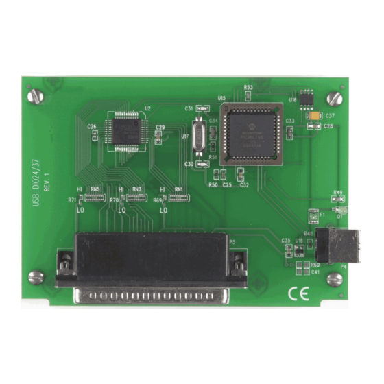
Page 8: Functional Details
Chapter 3 Functional Details Components The USB-DIO24/37 has the following components, as shown in Figure 5. 37-pin I/O connector USB connector Figure 4. USB-DIO24/37 components 37-pin I/O connector The 37-pin connector provides 24 digital I/O, one counter, six ground, and two 5V power connections. -
Page 9: Usb Connector
5 V. No external power supply is required. The LED indicates the communication status of the USB-DIO24/37. It uses up to 5 mA of current and cannot be disabled. The table below explains the function of the USB-DIO24/37 LED. -
Page 10: Mechanical Drawings
USB-DIO24/37 User's Guide Functional Details Mechanical Drawings Figure 5. Circuit board dimensions... -
Page 11: Specifications
Chapter 4 Specifications All specifications are subject to change without notice. Typical for 25 °C unless otherwise specified. Specifications in italic text are guaranteed by design. Digital input/output Table 1. Digital I/O specifications Parameter Specification Digital type 82C55 Number of I/O 24 (Port A Bit 0 through Port C Bit7) Configuration 2 banks of 8 and 2 banks of 4, or 3 banks of 8... -
Page 12: Data Transfer Rates
60 mA max Note 2: This is the total current requirement for the USB-DIO24/37which includes up to 5 mA for the status LED. Note 3: Self-powered refers to USB hubs and hosts with a power supply. Bus-powered refers to USB hubs and hosts without their own power supply. -
Page 13: Mechanical
USB-DIO24/37 User's Guide Specifications Mechanical Table 7. Mechanical specifications Parameter Specification Dimensions (L × W × H) 119 mm × 84 mm × 14 mm (4.69 × 3.31 × 0.55 in.) USB cable length 3 m (9.84 ft) max USB cable type A-B cable, UL type AWM 2527 or equivalent. -
Page 14: Declaration Of Conformity
Norton, MA 02766 Category: Electrical equipment for measurement, control and laboratory use. Measurement Computing Corporation declares under sole responsibility that the product USB-DIO24/37 to which this declaration relates is in conformity with the relevant provisions of the following standards or other... - Page 15 Measurement Computing Corporation NI Hungary Kft 10 Commerce Way H-4031 Debrecen, Hátar út 1/A, Hungary Norton, Massachusetts 02766 Phone: +36 (52) 515400 (508) 946-5100 Fax: +36 (52) 515414 Fax: (508) 946-9500 http://hungary.ni.com/debrecen E-mail: info@mccdaq.com www.mccdaq.com...
Need help?
Do you have a question about the USB-DIO24 and is the answer not in the manual?
Questions and answers