
Related Manuals for Measurement Computing USB-1608FS-Plus-OEM


Summary of Contents for Measurement Computing USB-1608FS-Plus-OEM
- Page 1 USB-1608FS-Plus-OEM Analog and Digital I/O User's Guide Document Revision 2A December 2014 © Copyright 2014...
- Page 2 Other product and company names mentioned herein are trademarks or trade names of their respective companies. © 2014 Measurement Computing Corporation. All rights reserved. No part of this publication may be reproduced, stored in a retrieval system, or transmitted, in any form by any means, electronic, mechanical, by photocopying, recording, or otherwise without the prior written permission of Measurement Computing Corporation.
-
Page 3: Table Of Contents
What you will learn from this user's guide ......................5 Conventions in this user's guide ......................... 5 Where to find more information ......................... 5 Chapter 1 Introducing the USB-1608FS-Plus-OEM ..................... 6 Functional block diagram ........................... 7 Chapter 2 Installing a USB-1608FS-Plus-OEM ..................... 8 Unpacking................................ - Page 4 USB-1608FS-Plus-OEM User's Guide Memory ................................20 Microcontroller ..............................20 Power ................................21 General ................................21 Environmental ..............................21 Mechanical ............................... 21 Header connector and pinout ..........................21...
-
Page 5: Preface
Preface About this User's Guide What you will learn from this user's guide This user's guide describes the Measurement Computing USB-1608FS-Plus-OEM data acquisition device and lists device specifications. Conventions in this user's guide For more information Text presented in a box signifies additional information and helpful hints related to the subject matter you are reading. -
Page 6: Introducing The Usb-1608Fs-Plus-Oem
Two header connectors for field wiring connections The USB-1608FS-Plus-OEM device is compatible with both USB 1.1 and USB 2.0 ports. The speed of the device may be limited when using a USB 1.1 port due to the difference in transfer rates on the USB 1.1 versions of the protocol (low-speed and full-speed). -
Page 7: Functional Block Diagram
USB-1608FS-Plus-OEM User's Guide Introducing the USB-1608FS-Plus-OEM Functional block diagram USB-1608FS-Plus-OEM functions are illustrated in the block diagram shown here. Figure 1. Functional block diagram... -
Page 8: Installing A Usb-1608Fs-Plus-Oem
Installing on a Windows platform Connect the USB-1608FS-Plus-OEM to a to an available USB port on the computer running Windows, connect the USB cable to an available USB port on the computer or to an external USB hub connected to the computer. -
Page 9: Chapter 3 Functional Details
The analog value is converted to digital data and returned to the computer. You can repeat this procedure until you have the total number of samples that you want. The USB-1608FS-Plus-OEM can attain throughput rates up to 500 S/s using a software loop. This rate is system-dependent. -
Page 10: Board Components
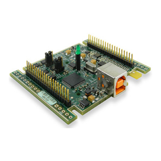
USB-1608FS-Plus-OEM User's Guide Functional Details Board components Board components are shown in Figure 2. Header connectors 21 to 40 USB connector Header connectors 1 to 20 Figure 2. Board components USB connector Receives the supplied USB cable. When connected to a computer or USB hub, the cable provides +5 V power and communication. -
Page 11: Header Connectors
USB-1608FS-Plus-OEM User's Guide Functional Details Header connectors The header connectors provide connections for the analog inputs, analog ground, DIO, clock I/O, trigger, counter, power output, and digital ground reference. Header connector pinout (refer to Figure 2 for pin numbering) Signal Description... -
Page 12: Digital I/O
Turn the device over and rest the top of the housing on a flat, stable surface. Caution! The discharge of static electricity can damage some electronic components. Before removing the USB-1608FS-Plus-OEM from its housing, ground yourself using a wrist strap or touch the computer chassis or other grounded object to eliminate any stored static charge. -
Page 13: Counter Input
Caution! The PC +5V connector is an output. Do not connect it to an external power supply or you may damage the device and possibly the computer. The maximum output current that can be drawn by the USB-1608FS-Plus-OEM is 500 mA. This maximum applies to most personal computers and self-powered USB hubs. Bus-powered hubs and notebook computers may limit the maximum available output current to 100 mA. -
Page 14: Accuracy
Any deviation from this is an offset error. Figure 7 shows the transfer function with an offset error. The typical offset error specification for a USB-1608FS-Plus-OEM on the ±10 V range is ±1.66 mV. Offset error affects all codes equally by shifting the entire transfer function up or down along the input voltage axis. - Page 15 Figure 8. ADC Transfer function with gain error For example, a USB-1608FS-Plus-OEM exhibits a typical calibrated gain error of ±0.04% on all ranges. For the ±10 V range, this would yield 10 V × ±0.0002 = ±4 mV. This means that at full scale, neglecting the effect of offset for the moment, the measurement would be within 4 mV of the actual value.
-
Page 16: Synchronized Operations
When the SYNC pin is configured as an output, the internal A/D pacer clock signal is sent to the header connector. You can output the clock to the SYNC pin of another device that is configured for A/D pacer input. Mechanical drawings Figure 10. USB-1608FS-Plus-OEM circuit board dimensions... -
Page 17: Chapter 4 Specifications
Chapter 4 Specifications All specifications are subject to change without notice. Typical for 25°C unless otherwise specified. Specifications in italic text are guaranteed by design. Analog input Table 1. General analog input specifications Parameter Condition Specification A/D converter type 16-bit successive approximation type Number of channels 8 single-ended Input configuration... -
Page 18: Noise Performance
±1 V 2.12 Table 4 summarizes the noise performance for the USB-1608FS-Plus-OEM. Noise distribution is determined by gathering 50 K samples with inputs tied to ground at the user connector. Samples are gathered at the maximum specified sampling rate of 100 kS/s. -
Page 19: External Trigger
USB-1608FS-Plus-OEM User's Guide Specifications External trigger Table 6. External trigger specifications Parameter Condition Specification Trigger source External digital TRIG_IN Trigger mode Software-selectable Edge or level sensitive: user configurable for CMOS compatible rising or falling edge, high or low level. Trigger latency 2 µs + 1 pacer clock cycle max... -
Page 20: Counter Section
USB-1608FS-Plus-OEM User's Guide Specifications Counter section Table 8. Counter specifications Parameter Specification Pin name Counter type Event counter Number of channels Schmitt trigger, 47 kΩ pull-down to ground Input type Input source CTR header pin Resolution 32 bits Schmitt trigger hysteresis 1.01 V typ... - Page 21 USB-1608FS-Plus-OEM User's Guide Specifications Power Table 11. Power specifications Parameter Condition Specification Supply current USB enumeration < 100 mA Supply current Including DIO and SYNC output loading < 500 mA +5V power available (Note 2) Connected to externally-powered root port hub or a 4.5 V min, 5.25 V max...
- Page 22 USB-1608FS-Plus-OEM User's Guide Specifications Table 16. Header connectors Signal Name Signal Name CH0 IN DIO0 AGND CH1 IN DIO1 AGND CH2 IN DIO2 AGND CH3 IN DIO3 AGND CH4 IN DIO4 AGND CH5 IN DIO5 AGND CH6 IN DIO6 AGND...
- Page 23 Measurement Computing Corporation 10 Commerce Way Suite 1008 Norton, Massachusetts 02766 (508) 946-5100 Fax: (508) 946-9500 E-mail: info@mccdaq.com www.mccdaq.com...
Need help?
Do you have a question about the USB-1608FS-Plus-OEM and is the answer not in the manual?
Questions and answers