Table of Contents
Advertisement
Quick Links
Download this manual
See also:
User Manual
Advertisement
Table of Contents

Related Manuals for Measurement Computing usb1608fs


Summary of Contents for Measurement Computing usb1608fs
- Page 1 USB-1608FS Analog Input and Digital I/O User's Guide Document Revision 7A January 2014 © Copyright 2014...
- Page 2 Other product and company names mentioned herein are trademarks or trade names of their respective companies. © 2014 Measurement Computing Corporation. All rights reserved. No part of this publication may be reproduced, stored in a retrieval system, or transmitted, in any form by any means, electronic, mechanical, by photocopying, recording, or otherwise without the prior written permission of Measurement Computing Corporation.
-
Page 3: Table Of Contents
Table of Contents Preface About this User's Guide ........................5 What you will learn from this user's guide ......................5 Conventions in this user's guide ......................... 5 Where to find more information ......................... 5 Chapter 1 Introducing the USB-1608FS........................ 6 Functional block diagram ........................... - Page 4 USB-1608FS User's Guide Microcontroller ..............................22 Power ................................23 General ................................23 Environmental ..............................23 Mechanical ............................... 23 Screw terminal connector and pinout ....................... 23 Declaration of Conformity ........................25...
-
Page 5: Preface
Preface About this User's Guide What you will learn from this user's guide This user's guide describes the Measurement Computing USB-1608FS data acquisition device and lists device specifications. Conventions in this user's guide For more information Text presented in a box signifies additional information and helpful hints related to the subject matter you are reading. -
Page 6: Introducing The Usb-1608Fs
Chapter 1 Introducing the USB-1608FS The USB-1608FS is an analog input and digital I/O data acquisition device providing the following features: Eight 16-bit single-ended (SE) analog input channels Each input channel has a dedicated A/D converter for simultaneous sampling. Software-selectable analog input ranges of ±10 V, ±5 V, ±2 V, and ±1 V ... -
Page 7: Installing The Usb-1608Fs
USB-1608FS from its packaging, ground yourself using a wrist strap or touch either the computer chassis or other grounded object to eliminate any stored static charge. If the device is damaged, notify Measurement Computing Corporation immediately by phone, fax, or email. ... -
Page 8: Calibrating The Hardware
You can calibrate the USB-1608FS with InstaCal. Perform calibration whenever the ambient temperature changes by more than ±10 °C from the last calibration. The Measurement Computing Manufacturing Test department performs the initial factory calibration. Contact Measurement Computing if you want to have the factory calibration coefficients restored. -
Page 9: Chapter 3 Functional Details
Chapter 3 Functional Details Analog input acquisition modes The USB-1608FS can acquire analog input data in three modes – software paced, hardware paced, and BURSTIO. Software paced The USB-1608FS acquires data one analog sample at a time using software-paced mode. You initiate the A/D conversion by calling a software command. -
Page 10: External Components
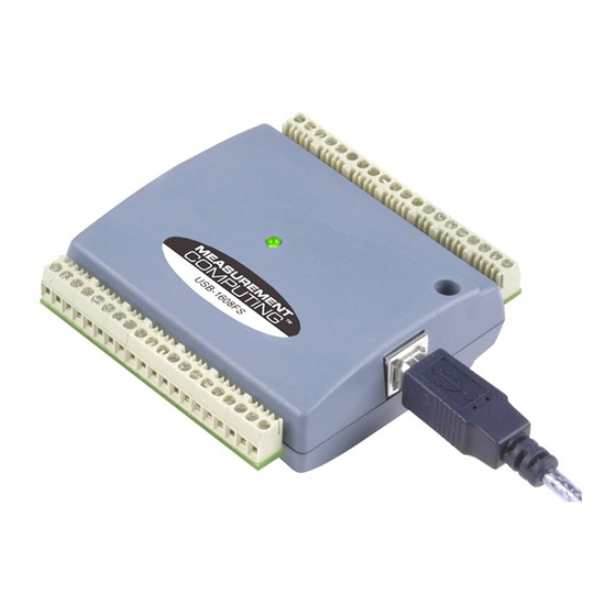
USB-1608FS User's Guide External components The external components – screw terminal banks, LED, and USB connector –are shown in Figure 2. Screw terminal pins 21 to 40 Screw terminal pins 1 to 20 USB connector Figure 2. USB-1608FS components USB connector The USB connector provides +5 V power and communication. -
Page 11: Signal Connections
USB-1608FS User's Guide Use 16 AWG to 30 AWG wire when making connections to the screw terminals. Pinout locations are shown in Figure 3 below. Figure 3. Screw terminal pinout Signal connections Analog input You can connect up to eight analog input connections to CH0 IN through CH7 IN... -
Page 12: Channel-Gain Queue
USB-1608FS User's Guide Channel-Gain queue The channel-gain queue feature allows you to configure a different gain setting for each analog input channel. The gain settings are stored in a channel-gain queue list that is written to local memory on the device. The channel-gain queue list must contain all eight channels listed in consecutive order. -
Page 13: Counter Input
USB-1608FS User's Guide The user-configurable jumper is labeled . Figure 5 shows the location of the jumper on the circuit board. Figure 5. Pull-up/down jumper location Configure the jumper for pull-up or pull-down, as shown in Figure 6. Figure 6. Pull-up/down jumper configuration Replace the top section of the housing, and fasten it to the bottom section with the three screws. -
Page 14: Ground
Maximum excess current = 500 mA – 170 mA = 330 mA Measurement Computing highly recommends that you figure in a safety factor of 20% below this maximum current loading for your applications. A conservative, safe user maximum in this case would be in the 250 mA to 300 mA range. - Page 15 USB-1608FS User's Guide Figure 7 shows an ideal, error-free, USB-1608FS transfer function. The typical calibrated accuracy of the USB-1608FS is range-dependent, as explained in the "Specifications" chapter. We use a ±10 V range as an example of what you can expect when performing a measurement in this range. Figure 7.
- Page 16 USB-1608FS User's Guide Figure 9. ADC Transfer function with gain error For example, the USB-1608FS exhibits a typical calibrated gain error of ±0.04% on all ranges. For the ±10 V range, this would yield 10 V × ±0.0002 = ±4 mV. This means that at full scale, neglecting the effect of offset for the moment, the measurement would be within 4 mV of the actual value.
-
Page 17: Synchronized Operations
USB-1608FS User's Guide Synchronized operations You can run up to two USB-1608FS devices on most computers. You can connect the SYNC pin of two devices together in a master/slave configuration and acquire data from the analog inputs of both devices using one clock. -
Page 18: Mechanical Drawings
USB-1608FS User's Guide Mechanical drawings Figure 11. Circuit board (top) and enclosure dimensions... -
Page 19: Chapter 4 Specifications
Chapter 4 Specifications All specifications are subject to change without notice. Typical for 25 °C unless otherwise specified. Specifications in italic text are guaranteed by design. Analog input Table 1. Analog input specifications Parameter Condition Specification A/D converter type 16-bit successive approximation type Number of channels 8 single-ended Input configuration... -
Page 20: Digital I/O
USB-1608FS User's Guide Table 3. Accuracy components - All values are (±) Range % of Reading Gain error at FS (mV) Offset (mV) ±10 V 0.04 4.00 1.66 ±5 V 0.04 2.00 0.98 ±2 V 0.04 0.80 0.51 ±1 V 0.04 0.40 0.28... -
Page 21: External Trigger
USB-1608FS User's Guide External trigger Table 6. External trigger specifications Parameter Condition Specification Trigger source External digital TRIG_IN Trigger mode Software-selectable Edge sensitive: user configurable for CMOS compatible rising or falling edge. Trigger latency 10 µs max Trigger pulse width 1µs min Schmitt trigger, 47 kΩ... -
Page 22: Counter
USB-1608FS User's Guide Counter Table 8. Counter specifications Parameter Specification Pin name Counter type Event counter Number of channels Schmitt trigger, 47 kΩ pull-down to ground Input type Input source CTR screw terminal Resolution 32 bits Schmitt trigger hysteresis 1.01 V typ 0.6 V min 1.5 V max Input high voltage threshold... -
Page 23: Power
USB-1608FS User's Guide Power Table 11. Power specifications Parameter Condition Specification Supply current USB enumeration < 100 mA Supply current (Note 3) Continuous mode 150 mA PC +5 V voltage range (Note 4) Connected to self-powered hub 4.25 V min, 5.25 V max ... - Page 24 USB-1608FS User's Guide Table 16. Connector pinout Signal Name Signal Name CH0 IN DIO0 AGND CH1 IN DIO1 AGND CH2 IN DIO2 AGND CH3 IN DIO3 AGND CH4 IN DIO4 AGND CH5 IN DIO5 AGND CH6 IN DIO6 AGND CH7 IN DIO7 AGND SYNC...
-
Page 25: Declaration Of Conformity
Norton, MA 02766 Category: Electrical equipment for measurement, control and laboratory use. Measurement Computing Corporation declares under sole responsibility that the product USB-1608FS to which this declaration relates is in conformity with the relevant provisions of the following standards or other documents: EC EMC Directive 2004/108/EC: General Requirements, EN 61326-1:2006 (IEC 61326-1:2005). - Page 26 Measurement Computing Corporation 10 Commerce Way Suite 1008 Norton, Massachusetts 02766 (508) 946-5100 Fax: (508) 946-9500 E-mail: info@mccdaq.com www.mccdaq.com...
Need help?
Do you have a question about the usb1608fs and is the answer not in the manual?
Questions and answers