
Related Manuals for Measurement Computing USB-3105


Summary of Contents for Measurement Computing USB-3105
- Page 1 USB-3105 USB-based Analog Output User's Guide November 2017. Rev. 4 © Measurement Computing Corporation...
- Page 2 Other product and company names mentioned herein are trademarks or trade names of their respective companies. © 2017 Measurement Computing Corporation. All rights reserved. No part of this publication may be reproduced, stored in a retrieval system, or transmitted, in any form by any means, electronic, mechanical, by photocopying, recording, or otherwise without the prior written permission of Measurement Computing Corporation.
-
Page 3: Table Of Contents
What you will learn from this user's guide ......................5 Conventions in this user's guide ......................... 5 Where to find more information ......................... 5 Chapter 1 Introducing the USB-3105 ........................6 Overview: USB-3105 features ..........................6 USB-3105 block diagram ........................... 7 Chapter 2 Installing the USB-3105 ........................ - Page 4 USB-3105 User's Guide EU Declaration of Conformity ......................19...
-
Page 5: Preface
Preface About this User's Guide What you will learn from this user's guide This user's guide describes the Measurement Computing USB-3105 data acquisition device and lists device specifications. Conventions in this user's guide For more information Text presented in a box signifies additional information and helpful hints related to the subject matter you are reading. -
Page 6: Introducing The Usb-3105
Overview: USB-3105 features This user's guide contains all of the information you need to connect the USB-3105 to your computer and to the signals you want to control. The USB-3105 is part of the Measurement Computing brand of USB-based data acquisition products. -
Page 7: Usb-3105 Block Diagram
USB-3105 User's Guide Introducing the USB-3105 USB-3105 block diagram USB-3105 functions are illustrated in the block diagram shown here. Full-speed USB 2.0 Compliant Interface 4-channel Quad Analog Voltage Output 16 channels (16-bit) 8 channels Microcontroller SYNCLD Event Counter 1 channel (32-bit) Figure 2. -
Page 8: Installing The Usb-3105
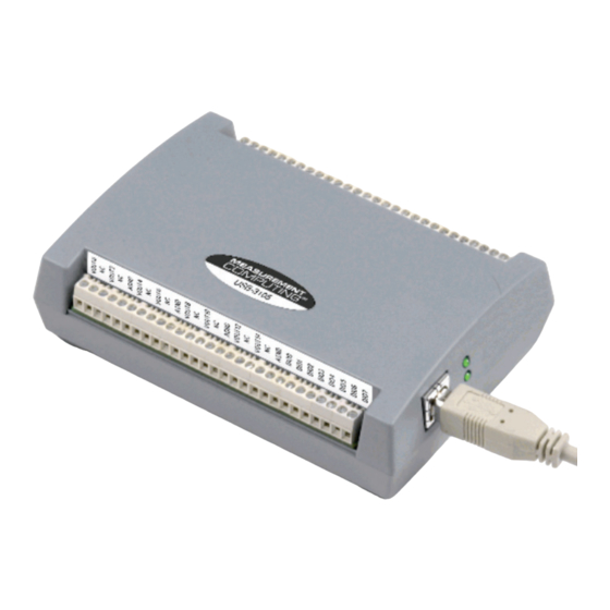
Installing the hardware To connect the USB-3105 to your system, connect the USB cable to an available USB port on the computer or to an external USB hub connected to the computer. Connect the other end of the USB cable to the USB connector on the device. -
Page 9: Functional Details
Status LED The Status LED indicates the communication status of the USB-3105. It flashes when data is being transferred, and is off when the USB-3105 is not communicating. This LED uses up to 10 mA of current and cannot be disabled. -
Page 10: Screw Terminal Banks
Screw terminal banks The USB-3105 has two rows of screw terminals—one row on the top edge of the housing, and one row on the bottom edge. Each row has 28 connections. Use 16 AWG to 30 AWG wire gauge when making screw terminal connections. -
Page 11: Analog Voltage Output Terminals (Vout0 To Vout15)
DIO5 54 DIO CTL DIO6 55 DGND DIO7 56 +5V Figure 5. USB-3105 signal pinout Analog voltage output terminals (VOUT0 to VOUT15) The screw terminal pins labeled are voltage output terminals (see Figure 5). The voltage VOUT0 VOUT15 output range for each channel is software-programmable for either bipolar or unipolar. The bipolar range is ±10 V, and the unipolar range is 0 to 10 V. -
Page 12: Digital I/O Control Terminal (Dio Ctl) For Pull-Up/Down Configuration
Configure as an output (master mode) to send the internal D/A LOAD signal to the SYNCLD pin. You can use the SYNCLD pin to synchronize with a second USB-3105 and simultaneously update the DAC outputs on each device. Refer to Synchronizing multiple units on page 13. -
Page 13: Synchronizing Multiple Units
DAC outputs of both devices. Do the following. Connect the SYNCLD pin of the master USB-3105 to the SYNCLD pin of the slave USB-3105. Configure the SYNCLD pin on the slave device for input to receive the D/A LOAD signal from the master device. -
Page 14: Specifications
100 Hz/#ch max, system dependent Note 1: The USB-3105 output voltage level defaults to 0V whenever the output voltage range is reconfigured. The USB-3105 output voltage level will also default to 0V: 1) Whenever the host PC is reset, shut down or suspended. -
Page 15: Analog Output Calibration
The maximum differential non-linearity specification applies to the entire 0 to 70 °C temperature range of the USB-3105. This specification also accounts for the maximum errors due to the software calibration algorithm (in Calibrated mode only) and the DAC8554 digital to analog converter non-linearities. -
Page 16: Synchronous Dac Load
USB-3105 User's Guide Specifications Synchronous DAC Load Table 7. SYNCLD I/O specifications Parameter Condition Specification Pin name SYNCLD (terminal block pin 49) Power on and reset state Input Pin type Bidirectional Termination Internal 100K ohms pull-down Software selectable direction Output Outputs internal D/A LOAD signal. -
Page 17: Memory
Note 7: This is the total quiescent current requirement for the USB-3105 which includes up to 10 mA for the status LED. This does not include any potential loading of the digital I/O bits, +5V user terminal, or the VOUTx outputs. -
Page 18: Mechanical
USB-3105 User's Guide Specifications Humidity 0 to 90% non-condensing Mechanical Table 14. Mechanical specifications Parameter Specification Dimensions (L × W × H) 127 × 89.9 × 35.6 mm (5.00 × 3.53 × 1.40 in.) Screw terminal connector Table 15. Main connector specifications... - Page 19 October 10, 2017, Norton, Massachusetts USA Test Report Number: EMI4712.07/EMI5193.08 Measurement Computing Corporation declares under sole responsibility that the product USB-3105 is in conformity with the relevant Union Harmonization Legislation and complies with the essential requirements of the following applicable European Directives:...
- Page 20 Measurement Computing Corporation NI Hungary Kft 10 Commerce Way H-4031 Debrecen, Hátar út 1/A, Hungary Norton, Massachusetts 02766 Phone: +36 (52) 515400 (508) 946-5100 Fax: +36 (52) 515414 Fax: (508) 946-9500 http://hungary.ni.com/debrecen E-mail: info@mccdaq.com www.mccdaq.com...
Need help?
Do you have a question about the USB-3105 and is the answer not in the manual?
Questions and answers