Table of Contents
Advertisement
Quick Links
Advertisement
Table of Contents

Related Manuals for Measurement Computing USB-1616HS-BNC


Summary of Contents for Measurement Computing USB-1616HS-BNC
- Page 2 USB-1616HS-BNC User's Guide Document Revision 1, May, 2008 © Copyright 2008, Measurement Computing Corporation...
- Page 3 Measurement Computing. Thank you for choosing a Measurement Computing product—and congratulations! You own the finest, and you can now enjoy the protection of the most comprehensive warranties and unmatched phone tech support. It’s the embodiment of our mission: ...
- Page 4 Information furnished by Measurement Computing Corporation is believed to be accurate and reliable. However, no responsibility is assumed by Measurement Computing Corporation neither for its use; nor for any infringements of patents or other rights of third parties, which may result from its use. No license is granted by implication or otherwise under any patent or copyrights of Measurement Computing Corporation.
-
Page 5: Table Of Contents
Introducing the USB-1616HS-BNC ...................... 8 Overview: USB-1616HS-BNC features ......................8 Software features ..............................8 Chapter 2 Installing the USB-1616HS-BNC ......................9 What comes with your USB-1616HS-BNC shipment? ..................9 Hardware ..................................9 Optional components ...............................10 Additional documentation ..............................10 Unpacking the USB-1616HS-BNC ........................10 Installing the software ............................ - Page 6 Using the setpoint status register............................33 Examples of control outputs ............................34 Detection setpoint details ..............................38 DAC or timer update latency ............................38 Chapter 4 Calibrating the USB-1616HS-BNC ..................... 40 Chapter 5 Specifications ............................41 Analog input ..............................41 Accuracy ..................................42 Analog outputs ..............................42 Digital input/output............................
-
Page 7: Preface
About this User's Guide What you will learn from this user's guide This user's guide explains how to install, configure, and use the USB-1616HS-BNC so that you get the most out of its analog I/O, digital I/O, and counter/timer I/O features. -
Page 8: Introducing The Usb-1616Hs-Bnc
You can operate all analog I/O, digital I/O, and counter/timer I/O synchronously. Software features For information on the features of InstaCal and the other software included with your USB-1616HS-BNC, refer to the Quick Start Guide that shipped with your device. The Quick Start Guide is also available in PDF at www.mccdaq.com/PDFmanuals/DAQ-Software-Quick-Start.pdf. -
Page 9: Installing The Usb-1616Hs-Bnc
USB cable (2-meter length) TR-2U power supply and CA-1* line cord AC-to-DC conversion power supply and cord plugs into the external power connector of the USB-1616HS- BNC. * European customers: Contact Measurement Computing to order the CA-261 line cord for your region. -
Page 10: Optional Components
USB-1616HS-BNC User's Guide Installing the USB-1616HS-BNC Optional components If you ordered any of the following products with your USB-1616HS-BNC, they should be included with your shipment. Cables C37FM-x cable Signal conditioning accessories Measurement Computing provides signal termination products for use with the USB-1616HS-BNC. Refer to the "Field wiring and signal termination... -
Page 11: Installing The Hardware
The USB-1616HS-BNC requires 9 V of external power. Connect the USB cable to the USB-1616HS-BNC USB connector and to a USB port on your computer. A USB2.0 port is recommended—connecting to a USB1.1 port results in lower performance. When you connect the USB-1616HS-BNC for the first time, a... -
Page 12: Connecting The Board For I/O Operations
USB-1616HS-BNC User's Guide Installing the USB-1616HS-BNC Connecting the board for I/O operations Connectors, cables – main I/O connector The following table lists the board I/O connector type, compatible cables, and compatible accessory products for the USB-1616HS-BNC. Board connectors, cables, and accessory equipment ... -
Page 13: Cabling
USB-1616HS-BNC User's Guide Installing the USB-1616HS-BNC Cabling Use a C37FM-x 37-pin cable to connect to the USB-1616HS-BNC's 37-pin device I/O connector. The red stripe identifies pin # 1 Female connector Male connector Figure 1. C37FM-x cable Field wiring and signal termination accessories You can connect the USB-1616HS-BNC to the following accessory boards using the C37FM-x cable. -
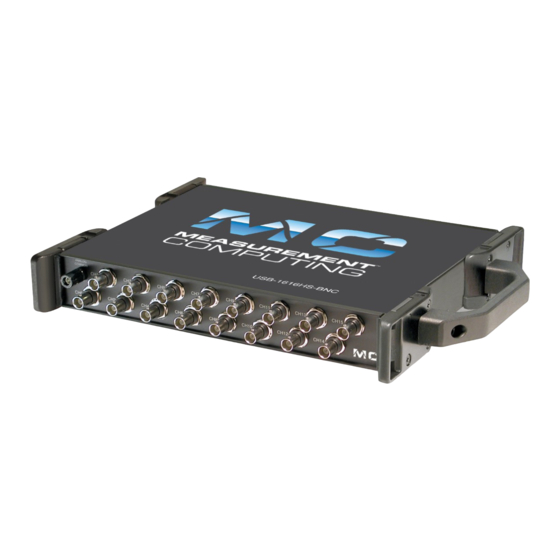
Page 14: Functional Details
Figure 2. USB-1616HS-BNC components – front view Figure 3. USB-1616HS-BNC components – rear view External power connector (DC IN) The USB-1616HS-BNC requires external power. Connect the TR-2U power supply to the external power supply connector. This power supply provides 9 VDC power to the USB-1616HS-BNC. -
Page 15: Usb-1616Hs-Bnc Block Diagram
USB-1616HS-BNC User's Guide Functional Details USB-1616HS-BNC block diagram Figure 4 shows a simplified block diagram of the USB-1616HS-BNC. This device provides all of the functional elements shown in the figure. Figure 4. USB-1616HS-BNC functional block diagram Synchronous I/O – mixing analog, digital, and counter scanning The USB-1616HS-BNC can read analog, digital, and counter inputs, while generating up to two analog outputs and digital pattern outputs at the same time. - Page 16 USB-1616HS-BNC User's Guide Functional Details For example, in the fastest mode, with ADC settling time set to 1 µs, a single analog channel can be scanned continuously at 1 MS/s; two analog channels can be scanned at 500 kS/s each; 16 analog input channels can be scanned at 62.5 kS/s.
- Page 17 PC is 2.167 MS/s. Some slower PCs may have a problem with data bandwidths greater than 6 MS/s. The USB-1616HS-BNC has an onboard 1 MS buffer for acquired data. Example: Sampling digital inputs for every analog sample in a scan group The scan is programmed pre-acquisition and is made up of six analog channels (Ch0, Ch2, Ch5, Ch11, Ch13, Ch15) and four digital channels (16-bits of digital input, three counter inputs.) Each of the analog channels can...
-
Page 18: Analog Output
Analog output The USB-1616HS-BNC has two 16-bit, 1 MHz analog output channels. Analog outputs can be updated at a maximum rate of 1 MHz. The channels have an output range of -10 V to +10 V. Each D/A can continuously output a waveform. In addition, a program can asynchronously output a value to any of the D/A channels for non-waveform applications, assuming that the D/A is not already being used in the waveform output mode. -
Page 19: Digital I/O
You can also synchronize everything—input scans, DACs, pattern digital outputs—to one clock, which is either internally-generated or externally-applied. Digital I/O Sixteen TTL-level digital I/O lines are included in each USB-1616HS-BNC. You can program digital I/O in 8-bit groups as either inputs or outputs and scan them in several modes (see "Digital input scanning"... -
Page 20: Digital Outputs And Pattern Generation
Digital outputs can be updated asynchronously at any time before, during, or after an acquisition. You can use both 8-bit ports to generate a digital pattern at up to 4 MHz. The USB-1616HS-BNC supports digital pattern generation. The digital pattern can be read from PC RAM. -
Page 21: Software-Based Triggering
Software-based triggering usually results in a long period of inactivity between the trigger condition being detected and the data being acquired. However, the USB-1616HS-BNC avoids this situation by using pre- trigger data. When software-based-triggering is used, and the PC detects the trigger condition—which may be thousands of readings after the actual occurrence of the signal—the USB-1616HS-BNC driver automatically... -
Page 22: Counter Inputs
You set the amount of pre-trigger data to acquire. Then, the system continues to acquire data until the program issues a command to halt acquisition. Counter inputs Four 32-bit counters are built into the USB-1616HS-BNC. Each counter accepts frequency inputs up to 20 MHz. USB-1616HS-BNC counter channels can be configured as standard counters or as multi-axis quadrature encoders. -
Page 23: Counter Modes
Sets the signal on the mapped counter input to latch the count. By default, the start of scan signal—a signal internal to the USB-1616HS-BNC that pulses once every scan period to indicate the start of a scan group—latches the count so that the count is updated each time a scan is... -
Page 24: Debounce Modes
USB-1616HS-BNC User's Guide Functional Details Gating "on" mode Sets the gating option to "on" for the mapped channel, enabling the mapped channel to gate the counter. Any counter can be gated by the mapped channel. When the mapped channel is high, the counter is enabled by default. - Page 25 USB-1616HS-BNC User's Guide Functional Details Figure 11. Debounce module – trigger after stable mode The following time periods (T1 through T5) pertain to Figure 11. In trigger after stable mode, the input signal to the debounce module is required to have a period of stability after an incoming edge, in order for that edge to be accepted (passed through to the counter module.) The debounce time for this example is equal to T2 and T5.
- Page 26 USB-1616HS-BNC User's Guide Functional Details Debounce mode comparisons Figure 13 shows how the two modes interpret the same input signal, which exhibits glitches. Notice that the trigger before stable mode recognizes more glitches than the trigger after stable mode. Use the bypass option to achieve maximum glitch recognition.
-
Page 27: Encoder Mode
The USB-1616HS-BNC supports quadrature encoders with up to 2 billion pulses per revolution, 20 MHz input frequencies, and x1, x2, x4 count modes. - Page 28 USB-1616HS-BNC User's Guide Functional Details Figure 16. Representation of rotary shaft quadrature encoder The concentric pattern for B has the same number of window pairs as A—except that the entire pattern is rotated by 1/4 of a window-pair. Thus the B signal is always 90 degrees out of phase from the A signal. The A and B signals pulse 512 times (or 1024, 4096, etc.) per complete rotation of the encoder.
- Page 29 Functional Details Connecting the USB-1616HS-BNC to an encoder You can use up to two encoders with each USB-1616HS-BNC in your acquisition system. Each A and B signal can be made as a single-ended connection with respect to common ground. Differential applications are not supported.
-
Page 30: Timer Outputs
Figure 19. Two encoders connected to DSUB37 pins on the USB-1616HS-BNC Timer outputs Two 16-bit timer outputs are built into every USB-1616HS-BNC. Each timer output can generate a different square wave with a programmable frequency in the range of 16 Hz to 1 MHz. -
Page 31: Using Detection Setpoints For Output Control
Using detection setpoints for output control What are detection setpoints? With the USB-1616HS-BNC's setpoint configuration feature, you can configure up to 16 detection setpoints associated with channels in a scan group. Each setpoint can update the following, allowing for real-time control based on acquisition data: ... -
Page 32: Setpoint Configuration
Detection setpoints act on 16-bit data only. Since the USB-1616HS-BNC has 32-bit counters, data is returned 16-bits at a time. The lower word, the higher word, or both lower and higher words can be part of the scan group. -
Page 33: Using The Setpoint Status Register
USB-1616HS-BNC User's Guide Functional Details Set low limit You can set the 16-bit low limit (limit B) when configuring the USB-1616HS-BNC through software. Set criteria Inside window: Signal is below 16-bit high limit and above 16-bit low limit. ... -
Page 34: Examples Of Control Outputs
USB-1616HS-BNC User's Guide Functional Details Examples of control outputs Detecting on analog input and DAC updates Update mode: Update on True and False Criteria: Channel 5 example: below limit; channel 4 example: inside window In this example, channel 5 is programmed with reference to one setpoint (limit A), defining a low limit. - Page 35 USB-1616HS-BNC User's Guide Functional Details Figure 24. Example 2: Analog inputs with setpoints update on True and False Detection on an analog input, timer output updates Update Mode: Update on True and False Criteria Used: Inside window Figure 25 shows how a setpoint can be used to update a timer output. Channel 3 is an analog input channel. A setpoint is applied using update on True and False, with a criteria of inside-the-window, where the signal value is inside the window when simultaneously less than Limit A but greater than Limit B.
- Page 36 USB-1616HS-BNC User's Guide Functional Details Criteria used: Window criteria for above and below the set limits Figure 26 shows analog input Channel 3 with a setpoint which defines two 16-bit limits, Limit A (High) and Limit B (Low). These are being applied in the hysteresis mode and DAC channel 0 is updated accordingly.
- Page 37 USB-1616HS-BNC User's Guide Functional Details DAC1 0.0 V Figure 27. Using two criteria to control an output* The update on True-only mode was selected, and therefore the updates for DAC1 only occur when the criteria is met. However, in the above figure we see that there are two setpoints acting on one DAC. We can also see that the two criteria can be met simultaneously.
-
Page 38: Detection Setpoint Details
USB-1616HS-BNC User's Guide Functional Details Detection setpoint details Controlling analog and timer outputs You can program each setpoint with a 16-bit DAC update value, and any one of the two DAC outputs can be updated in real time. Any setpoint can also be programmed with a timer update value. - Page 39 USB-1616HS-BNC User's Guide Functional Details Due to the pipelined architecture of the analog-to-digital converter system, the setpoint cannot be evaluated until 2 µs after the ADC conversion. Analog outputs have a 3µs delay due to the shifting of the digital data out to the D/A converter which takes 1 µs, plus the actual conversion time of the D/A converter (another 2 µs, worst case).
-
Page 40: Calibrating The Usb-1616Hs-Bnc
Chapter 4 Calibrating the USB-1616HS-BNC Every range of a USB-1616HS-BNC device is calibrated at the factory using a digital NIST traceable calibration method. This method works by storing a correction factor for each range on the unit at the time of calibration. -
Page 41: Specifications
Chapter 5 Specifications Typical for 25 °C unless otherwise specified. Specifications in italic text are guaranteed by design. Analog input Table 1. Analog input specifications A/D converter type Successive approximation Resolution 16 bits Number of channels 16 differential Input ranges (software and sequencer Bipolar: ±10 V, ±5 V, ±2 V, ±1 V , ±0.5 V, ±0.2 V, ±0.1 V programmable) Maximum sample rate... -
Page 42: Accuracy
USB-1616HS-BNC User's Guide Specifications Accuracy Table 2. Analog input accuracy specifications Voltage range Accuracy Temperature coefficient Noise (cts ±(% of reading + % ±(ppm of reading + ppm range)/°C RMS) range) 23°C ±10 °C, 1 year -10 V to 10 V 0.031% + 0.008%... -
Page 43: Digital Input/Output
USB-1616HS-BNC User's Guide Specifications Digital input/output Table 4. Digital input/output specifications Number of I/O Ports Two banks of eight. Each port is programmable as input or output Input scanning modes Two programmable Asynchronous, under program control at any time relative to input scanning ... -
Page 44: Input Sequencer
USB-1616HS-BNC User's Guide Specifications Input sequencer Analog, digital, and counter inputs can be scanned based on either an internal programmable timer or an external clock source. Table 6. Input sequencer specifications Input scan clock sources: two (see Note 3) Internal, programmable: ... -
Page 45: Triggering
USB-1616HS-BNC User's Guide Specifications Triggering Table 7. Trigger sources and modes Trigger source Explanation Single channel analog Any analog input channel can be software programmed as the analog trigger channel, hardware trigger including any of the analog expansion channels. Input signal range: -10 V to +10 V maximum ... -
Page 46: Usb Specifications
USB-1616HS-BNC User's Guide Specifications USB specifications Table 11. USB specifications USB-device type USB 2.0 high-speed mode (480 Mbps) if available (recommended), otherwise, USB1.1 full-speed mode (12 Mbps) Device compatibility USB 2.0 (recommended) or USB 1.1 Environmental Table 12. Environmental specifications Operating temperature range -30 °C to +70 °C... - Page 47 USB-1616HS-BNC User's Guide Specifications Table 15. USB-1616HS-BNC 37-pin DSUB connector pin out Pin number Name Description SELFCAL Self-calibration. Factory use only. Do not connect. DAC0 Digital-to-analog converter; analog output 0 AGND Analog common TMR1 Timer output 1; 16-bit, frequency pulse generator output...
-
Page 48: Declaration Of Conformity
I/O cables must be less than 3 meters (9.75 feet) in length and shielded, with the shields connected to the USB-1616HS-BNC chassis. This connection is to be made via the jack screws of the Digital I/O connector located on the rear panel. - Page 49 Measurement Computing Corporation 10 Commerce Way Suite 1008 Norton, Massachusetts 02766 (508) 946-5100 Fax: (508) 946-9500 E-mail: info@mccdaq.com www.mccdaq.com...
Need help?
Do you have a question about the USB-1616HS-BNC and is the answer not in the manual?
Questions and answers