PaloAlto Networks PA-7000 Series Hardware Reference Manual
Hide thumbs
Also See for PA-7000 Series:
- Hardware reference manual (220 pages) ,
- Hardware reference manual (50 pages) ,
- Hardware reference manual (206 pages)
Table of Contents
Advertisement
Quick Links
Advertisement
Table of Contents

Related Manuals for PaloAlto Networks PA-7000 Series


Summary of Contents for PaloAlto Networks PA-7000 Series
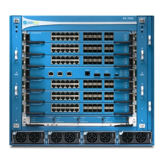
- Page 1 PA-7000 Series Firewall Hardware Reference paloaltonetworks.com/documentation...
- Page 2 2018-2019 Palo Alto Networks, Inc. Palo Alto Networks is a registered trademark of Palo © Alto Networks. A list of our trademarks can be found at www.paloaltonetworks.com/company/ trademarks.html. All other marks mentioned herein may be trademarks of their respective companies. Last Revised October 10, 2019 PA-7000 SERIES FIREWALL HARDWARE REFERENCE |...
-
Page 3: Table Of Contents
PA-7000 20GXM NPC........................51 PA-7000 20GQ NPC........................51 PA-7000 20GQXM NPC......................53 PA-7000 100G NPC........................53 Identify PA-7000 Series NPC Port Activity and Link LEDs..........57 PA-7000 Series Firewall Installation............59 PA-7000 Series Firewall Equipment Rack Installation..............61 PA-7000 Series Firewall Rack Install Safety Information...........61 Install the PA-7050 Firewall in the Mid-Mount Position........... - Page 4 Install the PA-7080 Firewall EMI Filter.................... 110 Service the PA-7000 Series Firewall Hardware........111 Replace a PA-7000 Series Firewall AC or DC Power Supply............113 Interpret the PA-7000 Series Firewall Power Supply LEDs..........113 Replace a PA-7000 Series AC Power Supply..............114 Replace a PA-7000 Series DC Power Supply..............117...
-
Page 5: Before You Begin
Before You Begin Read the following topics before you install or service a Palo Alto Networks next-generation ® firewall or appliance. The following topics apply to all Palo Alto Networks firewalls and appliances except where noted. > Tamper Proof Statement >... - Page 6 PA-7000 SERIES FIREWALL HARDWARE REFERENCE | Before You Begin 2019 Palo Alto Networks, Inc. ©...
-
Page 7: Tamper Proof Statement
• The integrity of the warranty label on the firewall or appliance is not compromised. (PA-7000 Series firewalls only) PA-7000 Series firewalls are modular systems and therefore do not include a warranty label on the firewall. PA-7000 SERIES FIREWALL HARDWARE REFERENCE | Before You Begin 2019 Palo Alto Networks, Inc. -
Page 8: Third-Party Component Support
Third-Party Component Support Before you consider installing third-party hardware, read the Palo Alto Networks Third-Party Component Support statement. PA-7000 SERIES FIREWALL HARDWARE REFERENCE | Before You Begin 2019 Palo Alto Networks, Inc. ©... -
Page 9: Product Safety Warnings
• Le dispositif de protection doit être raccordé à la terre et un câble Ethernet blindé de catégorie 5E ou supérieure doit être utilisé. Caractéristiques techniques: PA-7000 SERIES FIREWALL HARDWARE REFERENCE | Before You Begin 2019 Palo Alto Networks, Inc. ©... - Page 10 • (PA-7000 Series firewalls only) When removing a fan tray from a PA-7000 Series firewall, first pull the fan tray out about 1 inch (2.5cm) and then wait a minimum of 10 seconds before extracting the entire fan tray. This allows the fans to stop spinning and helps you avoid serious injury when removing the fan tray.
- Page 11 • A suitably-rated DC mains disconnect device must be provided as part of the building installation. French Translation: Un interrupteur d'isolement suffisant doit être fourni pendant l'installation du bâtiment. PA-7000 SERIES FIREWALL HARDWARE REFERENCE | Before You Begin 2019 Palo Alto Networks, Inc. ©...
- Page 12 PA-7000 SERIES FIREWALL HARDWARE REFERENCE | Before You Begin...
-
Page 13: Pa-7000 Series Firewall Overview
PA-7000 Series Firewall Overview The PA-7000 Series firewalls (PA-7050 and PA-7080) are high performance modular firewalls designed for large enterprise and carrier class environments. These multi-blade chassis can leverage either AC or DC power and have hot-swappable Network Processing Cards (NPCs) to allow for expansion as needs grow. - Page 14 PA-7000 SERIES FIREWALL HARDWARE REFERENCE | PA-7000 Series Firewall Overview 2019 Palo Alto Networks, Inc. ©...
-
Page 15: Pa-7050 Front And Back Panel Descriptions
There are two PA-7050 fan tray models: • PA-7050-FAN—First-generation fan tray. These fan trays are interchangeable, so you can install them in either fan tray slot. PA-7000 SERIES FIREWALL HARDWARE REFERENCE | PA-7000 Series Firewall Overview 2019 Palo Alto Networks, Inc. ©... - Page 16 (PA-7050-FANTRAY-L-A on the left and the PA-7050- FANTRAY-R-A), the air filter is inserted into the right fan tray (PA-7050-FANTRAY-R-A). Network Processing Card Provides network connectivity. (NPC) PA-7000 SERIES FIREWALL HARDWARE REFERENCE | PA-7000 Series Firewall Overview 2019 Palo Alto Networks, Inc. ©...
-
Page 17: Pa-7050 Back Panel (Ac)
The following image shows the back panel of the PA-7050 firewall (with AC power supplies installed) and the table describes each back panel component. PA-7000 SERIES FIREWALL HARDWARE REFERENCE | PA-7000 Series Firewall Overview 2019 Palo Alto Networks, Inc. ©... - Page 18 For information on connecting power, see Connect Power to a PA-7000 Series Firewall. The AC PEMs are not field-serviceable. PA-7000 SERIES FIREWALL HARDWARE REFERENCE | PA-7000 Series Firewall Overview 2019 Palo Alto Networks, Inc. ©...
-
Page 19: Pa-7050 Front Panel (Dc)
The following image shows the back panel of the PA-7050 firewall (with DC power supplies installed). The AC inlets and switches are not functional and must remain covered using the provided cover plate. PA-7000 SERIES FIREWALL HARDWARE REFERENCE | PA-7000 Series Firewall Overview 2019 Palo Alto Networks, Inc. - Page 20 DC model does not have a Power Entry Modules (PEM); the DC power source connects directly to the front of the power supplies. For descriptions of the back panel components, see PA-7050 Back Panel (AC). PA-7000 SERIES FIREWALL HARDWARE REFERENCE | PA-7000 Series Firewall Overview 2019 Palo Alto Networks, Inc. ©...
-
Page 21: Pa-7080 Front And Back Panel Descriptions
The following image shows the front panel of the PA-7080 firewall (with AC power supplies installed) and the table describes each front panel component. PA-7000 SERIES FIREWALL HARDWARE REFERENCE | PA-7000 Series Firewall Overview 2019 Palo Alto Networks, Inc. ©... - Page 22 During normal operation, the Power LED is green and the Fault LED is off. If an individual fan fails on the fan tray, the Power LED turns off and the red Fault LED illuminates. PA-7000 SERIES FIREWALL HARDWARE REFERENCE | PA-7000 Series Firewall Overview 2019 Palo Alto Networks, Inc. ©...
- Page 23 On a PA-7080 firewall, you can install up to 10 NPCs (in slots 1, 2, 3, 4, 5, 8, 9, 10, 11, and/or slot 12). You must have at least PA-7000 SERIES FIREWALL HARDWARE REFERENCE | PA-7000 Series Firewall Overview 2019 Palo Alto Networks, Inc.
-
Page 24: Pa-7080 Back Panel (Ac)
The following image shows the back panel of the PA-7080 firewall (with AC power supplies installed) and the table describes each back panel component. PA-7000 SERIES FIREWALL HARDWARE REFERENCE | PA-7000 Series Firewall Overview 2019 Palo Alto Networks, Inc. ©... - Page 25 Item Component Description Exhaust vent Provides air circulation for chassis cooling. Do not obstruct this vent. PA-7000 SERIES FIREWALL HARDWARE REFERENCE | PA-7000 Series Firewall Overview 2019 Palo Alto Networks, Inc. ©...
-
Page 26: Pa-7080 Front Panel (Dc)
DC model can hold up to eight DC power supplies instead of AC power supplies. For descriptions of the front panel components, see PA-7080 Front Panel (AC) and for information on connecting power, see Connect Power to a PA-7000 Series Firewall. PA-7000 SERIES FIREWALL HARDWARE REFERENCE | PA-7000 Series Firewall Overview 2019 Palo Alto Networks, Inc. ©... -
Page 27: Pa-7080 Back Panel (Dc)
DC Power Entry Modules (PEMs) instead of two AC PEMs. Each DC PEM contains two terminal strips, which connect eight wires (4 red positive and 4 black negative). The DC PEMs are field replaceable. PA-7000 SERIES FIREWALL HARDWARE REFERENCE | PA-7000 Series Firewall Overview 2019 Palo Alto Networks, Inc. - Page 28 For information on replacing a DC PEM, see Replace a PA-7080 DC PEM and for descriptions of the back panel components, see PA-7080 Back Panel (AC). PA-7000 SERIES FIREWALL HARDWARE REFERENCE | PA-7000 Series Firewall Overview...
-
Page 29: Pa-7000 Series Firewall Module And Interface Card Information
PA-7000 Series Firewall Module and Interface Card Information The PA-7000 Series firewalls are modular systems and requires a minimum set of front slot cards. The required cards include the Switch Management Card (SMC), Log Processing Card (LPC) or Log Forwarding Card (LFC), and at least one Network Processing Card (NPC). To expand port density and throughput, you can install a total of six NPCs in the PA-7050 firewall and ten NPCs in the PA-7080 firewall. - Page 30 PA-7000 SERIES FIREWALL HARDWARE REFERENCE | PA-7000 Series Firewall Module and Interface Card Information 2019 Palo Alto Networks, Inc. ©...
-
Page 31: Pa-7000 Series Firewall Switch Management Cards (Smcs)
PA-7000 Series Firewall Switch Management Cards (SMCs) The PA-7000 Series Switch Management Card (SMC) provides: switch fabric management for the chassis, system management access, stores PAN-OS, the firewall configuration, and management logs. It also includes ports for high availability (HA) connectivity and LED indicators that provides status of the chassis components. - Page 32 RJ-45 cable from your computer to the MGT port and browse to https:// 192.168.1.1. The default login name is admin and the default password is admin. PA-7000 SERIES FIREWALL HARDWARE REFERENCE | PA-7000 Series Firewall Module and Interface Card Information 2019 Palo Alto Networks, Inc.
- Page 33 Prior to PAN-OS 7.1, this port is disabled. For information on bootstrapping, refer to Bootstrap the Firewall in PAN-OS Administrator’s Guide Version 7.1. ® PA-7000 SERIES FIREWALL HARDWARE REFERENCE | PA-7000 Series Firewall Module and Interface Card Information 2019 Palo Alto Networks, Inc. ©...
-
Page 34: Pa-7000 Series Firewall Smc-B Component Descriptions
The following image shows the second-generation SMC (PA-7050 SMC-B and PA-7080 SMC-B), and the tables describe each SMC component. Figure 4: PA-7050-SMC-B PA-7000 SERIES FIREWALL HARDWARE REFERENCE | PA-7000 Series Firewall Module and Interface Card Information 2019 Palo Alto Networks, Inc. - Page 35 (not between a network switch or router). When directly connecting two PA-7050 or PA-7080 firewalls, use either a 40Gbps PA-7000 SERIES FIREWALL HARDWARE REFERENCE | PA-7000 Series Firewall Module and Interface Card Information 2019 Palo Alto Networks, Inc. ©...
- Page 36 Eight LEDs that indicate the status of various hardware components. For details on the LEDs, see Interpret the PA-7000 Series Firewall SMC LEDs. PA-7000 SERIES FIREWALL HARDWARE REFERENCE | PA-7000 Series Firewall Module and Interface Card Information 2019 Palo Alto Networks, Inc. ©...
-
Page 37: Pa-7000 Series Firewall Smc-B Requirements
SMC and the second-generation SMC-B LEDs is that the LOG LED on the SMC-B is replaced with a service (SVC) LED. PA-7000 SERIES FIREWALL HARDWARE REFERENCE | PA-7000 Series Firewall Module and Interface Card Information 2019 Palo Alto Networks, Inc. - Page 38 There is a hardware failure, which may include the following: (Alarm) • Voltage issue. • Power supply detected but not operational. • Fan failure. • Hard drive failure. PA-7000 SERIES FIREWALL HARDWARE REFERENCE | PA-7000 Series Firewall Module and Interface Card Information 2019 Palo Alto Networks, Inc. ©...
- Page 39 Service LED Slot Description Status empty empty PA-7000-100G-NPC empty empty PA-7080-SMC-B PA-7000-LFC empty empty empty empty empty PA-7000 SERIES FIREWALL HARDWARE REFERENCE | PA-7000 Series Firewall Module and Interface Card Information 2019 Palo Alto Networks, Inc. ©...
- Page 40 The LED is solid green if there is a network link. Because this interface is comprised of four 10Gbps links, the LED uses an AND operation for all four link states. PA-7000 SERIES FIREWALL HARDWARE REFERENCE | PA-7000 Series Firewall Module and Interface Card Information 2019 Palo Alto Networks, Inc.
- Page 41 The LED blinks green if there is network activity. Because this interface is comprised of four 10Gbps links, the LED uses an OR operation of all four activity states. PA-7000 SERIES FIREWALL HARDWARE REFERENCE | PA-7000 Series Firewall Module and Interface Card Information 2019 Palo Alto Networks, Inc.
-
Page 42: Pa-7000 Series Firewall Log Cards
PA-7000 Series Firewall Log Cards The PA-7000 Series firewalls support two log card models: the Log Processing Card (LPC) and the Log Forwarding Card (LFC). The difference between the LPC and the LFC is that the LPC stores logs locally and forward logs;... - Page 43 The LED is off if there is no activity. Fault The LED is red if a drive is missing or faulty. PA-7000 SERIES FIREWALL HARDWARE REFERENCE | PA-7000 Series Firewall Module and Interface Card Information 2019 Palo Alto Networks, Inc.
-
Page 44: Pa-7000 Series Firewall Log Forwarding Card (Lfc)
PAN-OS 9.0, ports 2, 3, 4, 5, 6, 7, 8, and 10 are disabled and LACP is not supported. Configure the ports in Device > Log Forwarding Card. PA-7000 SERIES FIREWALL HARDWARE REFERENCE | PA-7000 Series Firewall Module and Interface Card Information 2019 Palo Alto Networks, Inc. - Page 45 • Temperature above high temperature threshold. You may also see varying behavior for the ALM LED in an HA configuration as follows: PA-7000 SERIES FIREWALL HARDWARE REFERENCE | PA-7000 Series Firewall Module and Interface Card Information 2019 Palo Alto Networks, Inc.
- Page 46 Enter the following command to enable the SVC LED on the card in a specific slot: PA-7000 SERIES FIREWALL HARDWARE REFERENCE | PA-7000 Series Firewall Module and Interface Card Information 2019 Palo Alto Networks, Inc.
- Page 47 • Replace the first-generation SMC (PA-7050-SMC or PA-7080-SMC) with the second-generation (PA-7050-SMC-B or PA-7080-SMC-B). • (PA-7080 only) Install the PA-7080 Firewall EMI Filter to reduce electromagnetic interference. PA-7000 SERIES FIREWALL HARDWARE REFERENCE | PA-7000 Series Firewall Module and Interface Card Information 2019 Palo Alto Networks, Inc. ©...
-
Page 48: Pa-7000 Series Firewall Network Processing Cards (Npcs)
Network Processing Cards (NPCs) provide network connectivity for a PA-7000 Series firewall. To scale performance and capacity, you can install up to six NPCs in a PA-7050 firewall and up to ten NPCs in a PA-7080 firewall. If you plan on fully populating a PA-7000 Series firewall with NPCs, see Determine... - Page 49 1 NPC card. The lever release latches on each side slides upward to release the levers used to eject PA-7000 SERIES FIREWALL HARDWARE REFERENCE | PA-7000 Series Firewall Module and Interface Card Information 2019 Palo Alto Networks, Inc.
- Page 50 The card temperature is outside the temperature tolerance. The following table describes the functions and states of the Ethernet and SFP Port LEDs PA-7000 SERIES FIREWALL HARDWARE REFERENCE | PA-7000 Series Firewall Module and Interface Card Information 2019 Palo Alto Networks, Inc.
-
Page 51: Pa-7000 20Gxm Npc
4 million sessions and the PA-7000 20GXM NPC supports up to 8 million sessions. As of PAN-OS 9.0 and later, the PA-7000-20G NPC supports 3.2 million sessions. The PA-7000 Series firewall must have PAN-OS 7.1 or later installed to use the PA-7000-20GXM-NPC. - Page 52 Use the following information to learn how to interpret the LED dashboard and port LEDs located on the PA-7000 20GQ Network Processing Card (NPC). The following table describes the functions and states of the NPC LED dashboard. PA-7000 SERIES FIREWALL HARDWARE REFERENCE | PA-7000 Series Firewall Module and Interface Card Information 2019 Palo Alto Networks, Inc.
-
Page 53: Pa-7000 20Gqxm Npc
4 million sessions and the PA-7000 20GQXM NPC supports up to 8 million sessions. As of PAN-OS 9.0 and later, the PA-7000-20GQ NPC supports 3.2 million sessions. The PA-7000 Series firewall must have PAN-OS 7.1 or later installed to use the PA-7000-20GQXM-NPC. - Page 54 Use the following information to learn how to interpret the LED dashboard and port LEDs on the PA-7000 100G Network Processing Card (NPC). PA-7000 SERIES FIREWALL HARDWARE REFERENCE | PA-7000 Series Firewall Module and Interface Card Information 2019 Palo Alto Networks, Inc.
- Page 55 Enter the following command to disable the SVC LED: admin@PA-7080> set system setting service-led enable no PA-7000 SERIES FIREWALL HARDWARE REFERENCE | PA-7000 Series Firewall Module and Interface Card Information 2019 Palo Alto Networks, Inc.
- Page 56 • (PA-7080 only) Install the PA-7080 Firewall EMI Filter to reduce electromagnetic interference. PA-7000 SERIES FIREWALL HARDWARE REFERENCE | PA-7000 Series Firewall Module and Interface Card Information 2019 Palo Alto Networks, Inc. ©...
-
Page 57: Identify Pa-7000 Series Npc Port Activity And Link Leds
The following image shows how to identify the activity and link LEDs for the port types available on PA-7000 Series firewall NPCs. The image shows the port orientation if the NPC is in a horizontal position. For details on the functions and states of the LEDS, see... - Page 58 PA-7000 SERIES FIREWALL HARDWARE REFERENCE | PA-7000 Series Firewall Module and Interface Card Information...
-
Page 59: Pa-7000 Series Firewall Installation
PA-7000 Series Firewall Installation The PA-7000 Series firewalls are modular systems that require you to install several components, such as network cards, during the installation process. Due to the weight of the firewalls, we recommend that you first install the firewall chassis into the rack and then install the front slot cards. - Page 60 PA-7000 SERIES FIREWALL HARDWARE REFERENCE | PA-7000 Series Firewall Installation 2019 Palo Alto Networks, Inc. ©...
-
Page 61: Pa-7000 Series Firewall Equipment Rack Installation
PA-7000 Series Firewall Equipment Rack Installation PA-7000 Series firewalls are designed for installation in a standard 19-inch equipment rack in a mid-mount or front-mount position. Before you install the hardware, read PA-7000 Series Firewall Rack Install Safety Information. • Install the PA-7050 Firewall in the Mid-Mount Position •... - Page 62 Attach the rack-mount brackets to the rack using rack-mount screws (not provided) and tighten with a screwdriver. Install four screws on each side of the chassis. PA-7000 SERIES FIREWALL HARDWARE REFERENCE | PA-7000 Series Firewall Installation 2019 Palo Alto Networks, Inc.
-
Page 63: Install The Pa-7050 Firewall In The Front-Mount Position
25 screws to remove each of the four brackets (two brackets on each side). There is a total of 112 bracket screws (56 on each side). PA-7000 SERIES FIREWALL HARDWARE REFERENCE | PA-7000 Series Firewall Installation 2019 Palo Alto Networks, Inc. - Page 64 Remove the front brackets (A and B) and back brackets (C and D) from the chassis. The back brackets (C and D) are not needed in this configuration. PA-7000 SERIES FIREWALL HARDWARE REFERENCE | PA-7000 Series Firewall Installation 2019 Palo Alto Networks, Inc.
- Page 65 When swapping the brackets, rotate them 180 degrees so the screw holes line up and the rack mount holes are on the front of the chassis. PA-7000 SERIES FIREWALL HARDWARE REFERENCE | PA-7000 Series Firewall Installation 2019 Palo Alto Networks, Inc.
- Page 66 PA-7000 SERIES FIREWALL HARDWARE REFERENCE | PA-7000 Series Firewall Installation 2019 Palo Alto Networks, Inc.
- Page 67 Attach the chassis brackets to the rack using the provided rack mount screws and tighten with STEP 6 | a Phillips-head screwdriver. Install all four screws on each side of the chassis. PA-7000 SERIES FIREWALL HARDWARE REFERENCE | PA-7000 Series Firewall Installation 2019 Palo Alto Networks, Inc. ©...
-
Page 68: Install The Pa-7080 Firewall In The Mid-Mount Position
PA-7000 Series Firewall Rack Install Safety Information. STEP 2 | Remove eight screws from each front-mount bracket (one left and one right) and then remove the brackets. PA-7000 SERIES FIREWALL HARDWARE REFERENCE | PA-7000 Series Firewall Installation 2019 Palo Alto Networks, Inc. ©... - Page 69 To access the screw holes on the lower bracket, open the door located at the front of the bracket as shown in the following image. PA-7000 SERIES FIREWALL HARDWARE REFERENCE | PA-7000 Series Firewall Installation 2019 Palo Alto Networks, Inc. ©...
- Page 70 Secure the chassis to the rack using eight rack#mount screws (not included) on each side of the chassis and tighten with a Phillips-head screwdriver. PA-7000 SERIES FIREWALL HARDWARE REFERENCE | PA-7000 Series Firewall Installation 2019 Palo Alto Networks, Inc. ©...
-
Page 71: Install The Pa-7080 Firewall In The Front-Mount Position
PA-7000 Series Firewall Rack Install Safety Information. STEP 2 | Remove 16 screws from each mid-mount bracket (one left and one right) and then remove the brackets. PA-7000 SERIES FIREWALL HARDWARE REFERENCE | PA-7000 Series Firewall Installation 2019 Palo Alto Networks, Inc. ©... - Page 72 To access the lower bracket screw holes, open the door located at the front of the bracket as shown in the image. PA-7000 SERIES FIREWALL HARDWARE REFERENCE | PA-7000 Series Firewall Installation 2019 Palo Alto Networks, Inc. ©...
- Page 73 Secure the chassis to the rack using eight rack#mount screws (not included) on each side of the chassis and tighten with a Phillips-head screwdriver. PA-7000 SERIES FIREWALL HARDWARE REFERENCE | PA-7000 Series Firewall Installation 2019 Palo Alto Networks, Inc. ©...
- Page 74 PA-7000 SERIES FIREWALL HARDWARE REFERENCE | PA-7000 Series Firewall Installation 2019 Palo Alto Networks, Inc. ©...
-
Page 75: Install The Mandatory Pa-7000 Series Firewall Front Slot Cards
Install the Mandatory PA-7000 Series Firewall Front Slot Cards The PA-7000 Series firewalls require a minimum of three cards that you install in the front slots of the chassis. These cards are shipped separately from the chassis and include the following: The Switch Management Card (SMC) provides management connectivity to the chassis and HA connectivity;... - Page 76 STEP 4 | Close the handles and ensure that the SMC fully seats into the SMC slot. PA-7000 SERIES FIREWALL HARDWARE REFERENCE | PA-7000 Series Firewall Installation 2019 Palo Alto Networks, Inc. ©...
- Page 77 Ensure that the handles are in the open position. The following images show the first-generation SMC; the install procedure for the second- generation SMC-B is the same. PA-7000 SERIES FIREWALL HARDWARE REFERENCE | PA-7000 Series Firewall Installation 2019 Palo Alto Networks, Inc. ©...
- Page 78 PA-7000 SERIES FIREWALL HARDWARE REFERENCE | PA-7000 Series Firewall Installation 2019 Palo Alto Networks, Inc. ©...
-
Page 79: Install A Pa-7000 Series Firewall Log Card
Install a PA-7000 Series Firewall Log Card The PA-7000 Series firewall must have a log card installed to operate. You can install a Log Processing Card (LPC) or a Log Forwarding Card (LFC). To learn about the available log cards to help you determine which... - Page 80 The left and right inner levers have a micro-switch that will power off the card as soon as they are pulled to unlock the outer lever. PA-7000 SERIES FIREWALL HARDWARE REFERENCE | PA-7000 Series Firewall Installation 2019 Palo Alto Networks, Inc.
- Page 81 PA-7000 SERIES FIREWALL HARDWARE REFERENCE | PA-7000 Series Firewall Installation 2019 Palo Alto Networks, Inc. ©...
- Page 82 ESD grounding cable. Plug the banana clip end into one of the ESD ports located on the front of the chassis before handling ESD sensitive PA-7000 SERIES FIREWALL HARDWARE REFERENCE | PA-7000 Series Firewall Installation 2019 Palo Alto Networks, Inc.
- Page 83 The left and right inner levers have a micro-switch that will power off the card as soon as they are pulled to unlock the outer lever. PA-7000 SERIES FIREWALL HARDWARE REFERENCE | PA-7000 Series Firewall Installation 2019 Palo Alto Networks, Inc.
-
Page 84: Install A Pa-7000 Series Firewall Network Processing Card (Npc)
If you install an NPC in slot 1, the system configures ethernet1/1 and ethernet1/2 as a virtual wire. If you install an NPC in any other slot, the system does not apply a default configuration. PA-7000 SERIES FIREWALL HARDWARE REFERENCE | PA-7000 Series Firewall Installation 2019 Palo Alto Networks, Inc. ©... - Page 85 Firewall. • Install a PA-7000 Series Firewall NPC in a Single Chassis • Install a PA-7000 Series Firewall NPC in a High Availability (HA) Configuration • Configure a Log Card Port on a PA-7000 Series Firewall • Configure Session Distribution on a PA-7000 Series Firewall...
- Page 86 PA-7000 SERIES FIREWALL HARDWARE REFERENCE | PA-7000 Series Firewall Installation 2019 Palo Alto Networks, Inc. ©...
- Page 87 Important: When installing new NPCs in a PA-7000 Series firewall with high availability (HA) configured, PAN-OS puts the cards in a disabled state. This allows you to bring up both cards (one in each firewall) at the same time, so HA can start monitoring the cards.
- Page 88 If the cards are functioning properly, the status will show an output similar to the following: Slot...Component..Card Status..Config Status 3 ..PA-7000-20G-NPC .Up....Success STEP 5 | Connect the network cables and the NPCs are ready to process network traffic. PA-7000 SERIES FIREWALL HARDWARE REFERENCE | PA-7000 Series Firewall Installation 2019 Palo Alto Networks, Inc. ©...
- Page 89 Network Processing Card (NPC) using the type Log Card. This is required because the traffic processing and logging capabilities of a PA-7000 Series firewall exceeds the capabilities of the management port, which is the port used for these services on other firewall models.
-
Page 90: Configure Session Distribution On A Pa-7000 Series Firewall
For details, refer to Session Distribution Policies in the PAN-OS Administrator’s Guide. PA-7000 SERIES FIREWALL HARDWARE REFERENCE | PA-7000 Series Firewall Installation 2019 Palo Alto Networks, Inc. ©... -
Page 91: Connect Power To A Pa-7000 Series Firewall
Connect DC Power to a PA-7080 Firewall PA-7000 Series Power Configuration Options This topic describes power configuration options for PA-7000 Series firewalls. • PA-7050 firewall—Ships with either four AC or four DC power supplies preinstalled in the front power supply slots; you can change the power type (AC or DC) in the field. -
Page 92: Determine Pa-7000 Series Firewall Power Configuration Requirements
Determine PA-7000 Series Firewall Power Configuration Requirements The number of active power supplies required to operate a PA-7000 Series firewall depends on the power input that you connect to the power supplies (120VAC, 240VAC, or -48VDC), the number of Network Processing Cards (NPCs), and your power redundancy requirement. -
Page 93: Connect Ac Power To A Pa-7050 Firewall
Crimp a 6-AWG wire to the provided grounding lug and connect the other end to your earth STEP 5 | ground point. PA-7000 SERIES FIREWALL HARDWARE REFERENCE | PA-7000 Series Firewall Installation 2019 Palo Alto Networks, Inc. ©... - Page 94 AC power switches located on the back of the chassis. The chassis will power on. PA-7000 SERIES FIREWALL HARDWARE REFERENCE | PA-7000 Series Firewall Installation 2019 Palo Alto Networks, Inc.
-
Page 95: Connect Dc Power To A Pa-7050 Firewall
STEP 4 | Crimp a 6-AWG wire to the provided grounding lug and connect the other end to your earth ground point. PA-7000 SERIES FIREWALL HARDWARE REFERENCE | PA-7000 Series Firewall Installation 2019 Palo Alto Networks, Inc. ©... - Page 96 STEP 9 | After each DC cable is securely connected, power on the DC power source and the chassis will power on. PA-7000 SERIES FIREWALL HARDWARE REFERENCE | PA-7000 Series Firewall Installation 2019 Palo Alto Networks, Inc. ©...
-
Page 97: Connect Ac Power To A Pa-7080 Firewall
50 in-lbs. You can install the lug in a vertical or horizontal position. Be careful not to strip the threads on the nuts and lug studs. PA-7000 SERIES FIREWALL HARDWARE REFERENCE | PA-7000 Series Firewall Installation 2019 Palo Alto Networks, Inc. - Page 98 AC STEP 9 | power switches located on the back of the chassis. The chassis will power on. PA-7000 SERIES FIREWALL HARDWARE REFERENCE | PA-7000 Series Firewall Installation 2019 Palo Alto Networks, Inc. ©...
-
Page 99: Connect Dc Power To A Pa-7080 Firewall
Put the provided ESD wrist strap on your wrist ensuring that the metal contact is touching your STEP 2 | skin. Then attach (snap) one end of the ground cable to the wrist strap and remove the alligator PA-7000 SERIES FIREWALL HARDWARE REFERENCE | PA-7000 Series Firewall Installation 2019 Palo Alto Networks, Inc. ©... - Page 100 PEM numbers. For example, to install two additional power supplies, remove the covers over PEM A (3) and PEM B (3). PA-7000 SERIES FIREWALL HARDWARE REFERENCE | PA-7000 Series Firewall Installation 2019 Palo Alto Networks, Inc.
- Page 101 STEP 14 | After each DC cable is securely connected, power on the DC power source and the chassis will power on. PA-7000 SERIES FIREWALL HARDWARE REFERENCE | PA-7000 Series Firewall Installation 2019 Palo Alto Networks, Inc. ©...
-
Page 102: View Pa-7000 Series Firewall Power Statistics
View PA-7000 Series Firewall Power Statistics Use the following information to learn how to view active power statistics on a PA-7000 Series firewall to help you ensure power redundancy and to plan for growth. You can view the amount of power that each power supply is producing as well as the power rating for each hardware component. - Page 103 FANTRAY 2 PA-7080-FANTRAY Present PSA1 CP2500AC54TE 2500 (+) PSA2 CP2500AC54TE 2500 (+) PSA3 empty PSA4 empty PSB1 CP2500AC54TE 2500 (+) PSB2 CP2500AC54TE 2500 (+) PA-7000 SERIES FIREWALL HARDWARE REFERENCE | PA-7000 Series Firewall Installation 2019 Palo Alto Networks, Inc. ©...
- Page 104 (SMC, LPC or LFC, and NPCs) use 3740 watts. If you subtract 3740 from 10000, there is 6260 watts of power remaining. PA-7000 SERIES FIREWALL HARDWARE REFERENCE | PA-7000 Series Firewall Installation 2019 Palo Alto Networks, Inc.
-
Page 105: Connect Cables To A Pa-7000 Series Firewall
Links). The following images show the PA-7050 firewall and PA-7080 firewall cable connections. To install cable guides, see PA-7000 Series Firewall Equipment Rack Installation. PA-7000 SERIES FIREWALL HARDWARE REFERENCE | PA-7000 Series Firewall Installation 2019 Palo Alto Networks, Inc. ©... - Page 106 PA-7000 SERIES FIREWALL HARDWARE REFERENCE | PA-7000 Series Firewall Installation 2019 Palo Alto Networks, Inc. ©...
-
Page 107: Verify The Pa-7000 Series Firewall Lpc And Npc Configuration
Verify the PA-7000 Series Firewall LPC and NPC Configuration After you install the front-slot cards and power on the PA-7000 Series firewall (described in Connect Power to a PA-7000 Series Firewall), you can use the following information to verify the status of the Log Processing Card (LPC) and the Network Processing Cards (NPCs). -
Page 108: Verify The Pa-7000 Series Firewall Npc Configuration
Verify the PA-7000 Series Firewall NPC Configuration When you first set up a PA-7000 Series firewall, all NPC slots are ready to use. If you are working with a firewall that is already deployed, you should check slot status before adding a new NPC to ensure that the NPC slot is ready. - Page 109 For information on installing NPCs, see Replace a PA-7000 Series Network Processing Card (NPC) and for information on slot status indicators, see PA-7000 Series Front Slot States. PA-7000 SERIES FIREWALL HARDWARE REFERENCE | PA-7000 Series Firewall Installation 2019 Palo Alto Networks, Inc. ©...
-
Page 110: Install The Pa-7080 Firewall Emi Filter
Secure the filter to the chassis using the four captive screws (two screws on each side). STEP 2 | PA-7000 SERIES FIREWALL HARDWARE REFERENCE | PA-7000 Series Firewall Installation... -
Page 111: Service The Pa-7000 Series Firewall Hardware
Service the PA-7000 Series Firewall Hardware The following topics describes how to replace field-serviceable components on a PA-7000 Series firewall. For an overview of the hardware components, see PA-7000 Series Firewall Overview. > Replace a PA-7000 Series Firewall AC or DC Power Supply >... - Page 112 PA-7000 SERIES FIREWALL HARDWARE REFERENCE | Service the PA-7000 Series Firewall Hardware 2019 Palo Alto Networks, Inc. ©...
-
Page 113: Replace A Pa-7000 Series Firewall Ac Or Dc Power Supply
Replace a PA-7000 Series Firewall AC or DC Power Supply The following topics describe how to interpret the power supply LEDs and how to replace a PA-7000 Series firewall power supply. • Interpret the PA-7000 Series Firewall Power Supply LEDs •... -
Page 114: Replace A Pa-7000 Series Ac Power Supply
The front power supplies correspond directly to the power connection on the back of the chassis. For example, if you are facing the front of a PA-7050 chassis, the power supply PA-7000 SERIES FIREWALL HARDWARE REFERENCE | Service the PA-7000 Series Firewall Hardware 2019 Palo Alto Networks, Inc. - Page 115 ESD ports located on the front of the chassis before handling ESD sensitive hardware. For details on the ESD port location, see PA-7080 Front Panel (AC). PA-7000 SERIES FIREWALL HARDWARE REFERENCE | Service the PA-7000 Series Firewall Hardware 2019 Palo Alto Networks, Inc. ©...
- Page 116 Then pull the power supply toward you and remove it. PA-7000 SERIES FIREWALL HARDWARE REFERENCE | Service the PA-7000 Series Firewall Hardware 2019 Palo Alto Networks, Inc.
-
Page 117: Replace A Pa-7000 Series Dc Power Supply
The new power supply will turn on and the LED will turn green. Replace a PA-7000 Series DC Power Supply • Replace a PA-7050 DC Power Supply PA-7000 SERIES FIREWALL HARDWARE REFERENCE | Service the PA-7000 Series Firewall Hardware 2019 Palo Alto Networks, Inc. ©... - Page 118 STEP 7 | Remove the replacement power supply from the packaging and open the front ejector handle until it is fully open. PA-7000 SERIES FIREWALL HARDWARE REFERENCE | Service the PA-7000 Series Firewall Hardware 2019 Palo Alto Networks, Inc. ©...
- Page 119 Put the provided ESD wrist strap on your wrist ensuring that the metal contact is touching your STEP 1 | skin. Then attach (snap) one end of the ground cable to the wrist strap and remove the alligator PA-7000 SERIES FIREWALL HARDWARE REFERENCE | Service the PA-7000 Series Firewall Hardware 2019 Palo Alto Networks, Inc. ©...
- Page 120 Pull the door toward you from the left side to open, which will eject the power supply from the chassis. Pull the power supply toward you and remove it. PA-7000 SERIES FIREWALL HARDWARE REFERENCE | Service the PA-7000 Series Firewall Hardware 2019 Palo Alto Networks, Inc.
- Page 121 Plug the power cable into the corresponding AC power module on the back of the chassis and STEP 7 | turn on the power switch. PA-7000 SERIES FIREWALL HARDWARE REFERENCE | Service the PA-7000 Series Firewall Hardware 2019 Palo Alto Networks, Inc. ©...
-
Page 122: Replace A Pa-7080 Dc Pem
Remove the stud nuts and star washers from the DC studs that secure the DC cables to the PEM and then remove the cables. STEP 4 | Remove the eight screws that secure the PEM to the chassis. PA-7000 SERIES FIREWALL HARDWARE REFERENCE | Service the PA-7000 Series Firewall Hardware 2019 Palo Alto Networks, Inc. ©... - Page 123 DC lug to the DC studs with the star washers and nuts and torque to 50 in-lbs. Be careful not to strip the nuts and lug studs. Turn on the DC power feed. STEP 8 | PA-7000 SERIES FIREWALL HARDWARE REFERENCE | Service the PA-7000 Series Firewall Hardware 2019 Palo Alto Networks, Inc. ©...
-
Page 124: Replace A Pa-7000 Series Firewall Fan Tray
If you replace the PA-7050-FANTRAY-R-A fan tray, remove the air filter that is part of the fan tray. You will install the air filter after you install the replacement fan tray. PA-7000 SERIES FIREWALL HARDWARE REFERENCE | Service the PA-7000 Series Firewall Hardware 2019 Palo Alto Networks, Inc. - Page 125 Figure 9: PA-7050-FAN PA-7000 SERIES FIREWALL HARDWARE REFERENCE | Service the PA-7000 Series Firewall Hardware 2019 Palo Alto Networks, Inc. ©...
- Page 126 Turn the thumb screws to the right until they stop. This will lock the top and bottom latches to secure the tray to the chassis. Use a Phillips-head screwdriver to tighten the thumb screws. PA-7000 SERIES FIREWALL HARDWARE REFERENCE | Service the PA-7000 Series Firewall Hardware 2019 Palo Alto Networks, Inc.
- Page 127 On a DC model, shut down the DC circuit to the chassis and then restore power. PA-7000 SERIES FIREWALL HARDWARE REFERENCE | Service the PA-7000 Series Firewall Hardware 2019 Palo Alto Networks, Inc.
- Page 128 The fan tray status is managed by the SMC in slot 4, so the above output will show that both fan trays are in slot S4. PA-7000 SERIES FIREWALL HARDWARE REFERENCE | Service the PA-7000 Series Firewall Hardware 2019 Palo Alto Networks, Inc.
-
Page 129: Replace A Pa-7080 Fan Tray
Pushing the handles outward does not eject the fan tray; it unlocks the tray from the chassis. Only a small amount of pressure is required to operate the release handles. PA-7000 SERIES FIREWALL HARDWARE REFERENCE | Service the PA-7000 Series Firewall Hardware 2019 Palo Alto Networks, Inc. - Page 130 CLI command: admin@PA-7080> show system environmentals fan-tray To view the status of each fan on a fan tray, run the following command: PA-7000 SERIES FIREWALL HARDWARE REFERENCE | Service the PA-7000 Series Firewall Hardware 2019 Palo Alto Networks, Inc. ©...
- Page 131 The fan tray status is managed by the SMC in slot 6, so the output from the above command will show that both fan trays are in slot S6. PA-7000 SERIES FIREWALL HARDWARE REFERENCE | Service the PA-7000 Series Firewall Hardware 2019 Palo Alto Networks, Inc.
-
Page 132: Replace A Pa-7000 Series Firewall Air Filter
Push the filter in until the rear ball joint(s) snap into place. If you are installing a PA-7050- FANTRAY-R-A air filter, turn the air filter screws clockwise until tight. PA-7000 SERIES FIREWALL HARDWARE REFERENCE | Service the PA-7000 Series Firewall Hardware 2019 Palo Alto Networks, Inc. - Page 133 Figure 13: PA-7050 Chassis Air Filter PA-7000 SERIES FIREWALL HARDWARE REFERENCE | Service the PA-7000 Series Firewall Hardware 2019 Palo Alto Networks, Inc. ©...
- Page 134 Figure 14: PA-7050 FANTRAY-R-A Air Filter PA-7000 SERIES FIREWALL HARDWARE REFERENCE | Service the PA-7000 Series Firewall Hardware 2019 Palo Alto Networks, Inc. ©...
- Page 135 Figure 15: PA-7080 Air Filter PA-7000 SERIES FIREWALL HARDWARE REFERENCE | Service the PA-7000 Series Firewall Hardware 2019 Palo Alto Networks, Inc. ©...
-
Page 136: Replace A Pa-7000 Series Firewall Front Slot Card
Replace a PA-7000 Series Firewall Front Slot Card The PA-7000 Series firewalls require one Switch Management Card (SMC), one Log Processing Card (LPC), and at least one Network Processing Card (NPC). The procedures to replace a front slot card on a PA-7050 and PA-7080 firewall are almost identical. - Page 137 PA-7080-SMB, also remove the SSD drives and label the drives (Sys 1 and Sys2) to ensure that you install them in the same SSD slots on the replacement SMC-B (See Replace a PA-7050- SMC-B or PA-7080-SMC-B Drive). PA-7000 SERIES FIREWALL HARDWARE REFERENCE | Service the PA-7000 Series Firewall Hardware 2019 Palo Alto Networks, Inc. ©...
- Page 138 SMC, the default option is set in the configuration. If you configured an option other than the default, you will need to reconfigure the distribution policy after installing the new Session Distribution Policies). SMC (see PA-7000 SERIES FIREWALL HARDWARE REFERENCE | Service the PA-7000 Series Firewall Hardware 2019 Palo Alto Networks, Inc. ©...
-
Page 139: Replace A Pa-7000 Series Log Card
Replace a PA-7000 Series Log Card Use the following topics to learn how to replace a PA-7000 Series Log Processing Card (LPC) or a PA-7000 Series Log Forwarding Card (LFC). The LPC has disk drives that must be removed and re-installed, while the LFC does not contain disk drives. - Page 140 PA-7000 SERIES FIREWALL HARDWARE REFERENCE | Service the PA-7000 Series Firewall Hardware 2019 Palo Alto Networks, Inc. ©...
- Page 141 3 times in 30 minutes, it enters maintenance mode at which time you must power off the chassis until you replace the LFC. PA-7000 SERIES FIREWALL HARDWARE REFERENCE | Service the PA-7000 Series Firewall Hardware 2019 Palo Alto Networks, Inc.
- Page 142 When installing the card, push the outer lever in to lock the inner lever. Figure 16: PA-7050 LFC PA-7000 SERIES FIREWALL HARDWARE REFERENCE | Service the PA-7000 Series Firewall Hardware 2019 Palo Alto Networks, Inc. ©...
-
Page 143: Replace A Pa-7000 Series Network Processing Card (Npc)
If there is only one functioning NPC in the chassis and the NPC fails after three recovery attempts, the chassis will reboot to attempt to recover the card. PA-7000 SERIES FIREWALL HARDWARE REFERENCE | Service the PA-7000 Series Firewall Hardware 2019 Palo Alto Networks, Inc. - Page 144 LED to turn off. After the power LED is off, pull the outer ejector release levers toward you to pull the card out of the chassis. PA-7000 SERIES FIREWALL HARDWARE REFERENCE | Service the PA-7000 Series Firewall Hardware 2019 Palo Alto Networks, Inc.
- Page 145 The following images show the two versions of the PA-7000 20G NPCs. Figure 18: Install or Remove a PA-7000 20G Version 1 NPC PA-7000 SERIES FIREWALL HARDWARE REFERENCE | Service the PA-7000 Series Firewall Hardware 2019 Palo Alto Networks, Inc.
- Page 146 The small notches located near the hinge of the card levers are used to fully seat the card into the back connector of the slot. To prevent damage, ensure that the notches line up PA-7000 SERIES FIREWALL HARDWARE REFERENCE | Service the PA-7000 Series Firewall Hardware 2019 Palo Alto Networks, Inc.
- Page 147 Make note of the cable connections and then loosen the screws on each side of the card that STEP 2 | secure the NPC to the chassis. PA-7000 SERIES FIREWALL HARDWARE REFERENCE | Service the PA-7000 Series Firewall Hardware 2019 Palo Alto Networks, Inc. ©...
- Page 148 For slot status information and troubleshooting, see the following sections: PA-7000 Series Front Slot States PA-7000 Series Firewall Network Processing Card (NPC) Troubleshooting Commands. PA-7000 SERIES FIREWALL HARDWARE REFERENCE | Service the PA-7000 Series Firewall Hardware 2019 Palo Alto Networks, Inc. ©...
- Page 149 HA configuration HA, put it in this state. Failure The card has failed and needs to be replaced. Unsupported The card is not a supported type for this slot. PA-7000 SERIES FIREWALL HARDWARE REFERENCE | Service the PA-7000 Series Firewall Hardware 2019 Palo Alto Networks, Inc. ©...
- Page 150 To enable NPCs after inserting them into the same slot numbers on each chassis in an HA configuration, run the following command: PA-7000 SERIES FIREWALL HARDWARE REFERENCE | Service the PA-7000 Series Firewall Hardware 2019 Palo Alto Networks, Inc. ©...
- Page 151 3 target ha-pair You can use the ha-pair option in an HA configuration for many of the slot control commands. PA-7000 SERIES FIREWALL HARDWARE REFERENCE | Service the PA-7000 Series Firewall Hardware 2019 Palo Alto Networks, Inc. ©...
-
Page 152: Replace A Pa-7000 Series Firewall Lpc Drive
Remove the failed drive from the RAID 1 array. In this example, run the following command to remove drive A2 from the array: admin@PA-7080> request system raid slot s7 remove A2 PA-7000 SERIES FIREWALL HARDWARE REFERENCE | Service the PA-7000 Series Firewall Hardware 2019 Palo Alto Networks, Inc. ©... - Page 153 AMC from the chassis and then completely remove the AMC. The FAULT LED on the AMC that contains the failed drive will show red. PA-7000 SERIES FIREWALL HARDWARE REFERENCE | Service the PA-7000 Series Firewall Hardware 2019 Palo Alto Networks, Inc.
- Page 154 To view RAID status, run the following command: admin@PA-7080> show system raid detail 5. The following output shows that the RAID 1 array is functioning properly: PA-7000 SERIES FIREWALL HARDWARE REFERENCE | Service the PA-7000 Series Firewall Hardware 2019 Palo Alto Networks, Inc. ©...
- Page 155 : not in use card serial : 002901000061 Disk id A2 Present model : ST1000NX0423 size : 953869 MB status : active sync PA-7000 SERIES FIREWALL HARDWARE REFERENCE | Service the PA-7000 Series Firewall Hardware 2019 Palo Alto Networks, Inc. ©...
- Page 156 : 002901000089 Disk id A2 Present model : ST1000NX0423 size : 953869 MB status : active sync card serial : 002901000067 PA-7000 SERIES FIREWALL HARDWARE REFERENCE | Service the PA-7000 Series Firewall Hardware 2019 Palo Alto Networks, Inc. ©...
-
Page 157: Re-Index The Lpc Drives
For each NPC that is in the Up state, run the following command to power off the NPC(s): admin@PA-7050> request chassis admin-power-off slot <slot-number> PA-7000 SERIES FIREWALL HARDWARE REFERENCE | Service the PA-7000 Series Firewall Hardware 2019 Palo Alto Networks, Inc. ©... - Page 158 If you powered off the NPCs, power them back on by running the following commands: STEP 7 | To view the status of each NPC: admin@PA-7050> show PA-7000 SERIES FIREWALL HARDWARE REFERENCE | Service the PA-7000 Series Firewall Hardware 2019 Palo Alto Networks, Inc. ©...
- Page 159 You can also use the web interface to view logs. For example, to view the traffic logs, select Monitor > Logs > Traffic. PA-7000 SERIES FIREWALL HARDWARE REFERENCE | Service the PA-7000 Series Firewall Hardware 2019 Palo Alto Networks, Inc.
-
Page 160: Replace A Pa-7050-Smc-B Or Pa-7080-Smc-B Drive
Drive id Sys1 active sync Drive id Sys2 degraded pancfg clean Drive id Sys1 active sync Drive id Sys2 degraded panrepo clean PA-7000 SERIES FIREWALL HARDWARE REFERENCE | Service the PA-7000 Series Firewall Hardware 2019 Palo Alto Networks, Inc. ©... - Page 161 Remove the failed SMC-B from the chassis. The following images show the first-generation SMCs; the procedure is the same for the second-generation SMCs (SMC-B). PA-7000 SERIES FIREWALL HARDWARE REFERENCE | Service the PA-7000 Series Firewall Hardware 2019 Palo Alto Networks, Inc.
- Page 162 The following image show the PA-7050-SMC-B; the procedure to replace a PA-7080-SMC-B SSD is the same. PA-7000 SERIES FIREWALL HARDWARE REFERENCE | Service the PA-7000 Series Firewall Hardware 2019 Palo Alto Networks, Inc. ©...
- Page 163 The drive is added to the array and you are prompted to reboot. Upon reboot, the system behavior is the same as if an identical drive was replaced. PA-7000 SERIES FIREWALL HARDWARE REFERENCE | Service the PA-7000 Series Firewall Hardware 2019 Palo Alto Networks, Inc.
- Page 164 This procedure may require one extra automatic reboot to correctly set up the firewall (due to how automatic RAID selection functions). PA-7000 SERIES FIREWALL HARDWARE REFERENCE | Service the PA-7000 Series Firewall Hardware 2019 Palo Alto Networks, Inc. ©...
-
Page 165: Increase The Pa-7000 Series Firewall Lpc Log Storage Capacity
1TB drives with 2TB drives to double the log storage capacity to 4TBs. The logs on the 1TB drives will not be available after upgrading drives on a PA-7000 Series firewall that is running a PAN-OS 7.0.7 or earlier release. Even if this is acceptable, we recommend that you perform this upgrade during a maintenance window.If it is important... - Page 166 2. Gently pull the AMC release handle on drive A1 toward you until it stops to unlock the AMC from the chassis and then completely remove the AMC. PA-7000 SERIES FIREWALL HARDWARE REFERENCE | Service the PA-7000 Series Firewall Hardware 2019 Palo Alto Networks, Inc.
- Page 167 4. Copy the data from the 1TB (A2) drive to the newly installed 2TB (A1) drive: admin@PA-7080> request system raid slot s7 copy from A2 to A1 PA-7000 SERIES FIREWALL HARDWARE REFERENCE | Service the PA-7000 Series Firewall Hardware 2019 Palo Alto Networks, Inc. ©...
- Page 168 : 002901000063 Disk id A2 Present model : ST2000NX0253 size : 1907738 MB status : active sync card serial : 002901000064 PA-7000 SERIES FIREWALL HARDWARE REFERENCE | Service the PA-7000 Series Firewall Hardware 2019 Palo Alto Networks, Inc. ©...
- Page 169 2. Gently pull the AMC release handle on drive A1 toward you until it stops to unlock the AMC from the chassis and then completely remove the AMC. Do the same for drive A2. PA-7000 SERIES FIREWALL HARDWARE REFERENCE | Service the PA-7000 Series Firewall Hardware 2019 Palo Alto Networks, Inc.
- Page 170 : 002901000063 Disk id A2 Present model : ST2000NX0253 size : 1907738 MB status : not in use card serial : 002901000064 PA-7000 SERIES FIREWALL HARDWARE REFERENCE | Service the PA-7000 Series Firewall Hardware 2019 Palo Alto Networks, Inc. ©...
- Page 171 7. To upgrade the B1/B2 drive array, repeat these procedures replacing the drive designators. For example, replace A1 with B1 and A2 with B2 to upgrade the drives in the B1/B2 RAID 1 array. PA-7000 SERIES FIREWALL HARDWARE REFERENCE | Service the PA-7000 Series Firewall Hardware 2019 Palo Alto Networks, Inc.
- Page 172 PA-7000 SERIES FIREWALL HARDWARE REFERENCE | Service the PA-7000 Series Firewall Hardware...
-
Page 173: Pa-7000 Series Firewall Specifications
PA-7000 Series Firewall Specifications The following topics provide chassis and component specifications for the PA-7000 Series firewalls. The Log Cards (LPC and LFC) and Network Processing Cards (NPCs) are universal, so you can install them in a PA-7050 or PA-7080 firewall. Components that are not universal, such as power supplies, the Switch Management Card (SMC), fan trays, and the air filter are listed separately for each model. - Page 174 PA-7000 SERIES FIREWALL HARDWARE REFERENCE | PA-7000 Series Firewall Specifications 2019 Palo Alto Networks, Inc. ©...
-
Page 175: Pa-7000 Series Firewall Physical Specifications
Includes the chassis weight above, plus the SMC, LPC, ten NPCs, and eight AC power supplies. • Chassis (DC)—172 lbs (78 kg 17.88 g) PA-7000 SERIES FIREWALL HARDWARE REFERENCE | PA-7000 Series Firewall Specifications 2019 Palo Alto Networks, Inc. ©... - Page 176 • PA-7050 firewall—4.2 lbs (1 kg 905.09 g) • PA-7080 firewall—4 lbs (1 kg 814.37 g) Rack mount size • PA-7050 firewall—9U, 19” standard rack (15.75”H x 19”W x 24”D) PA-7000 SERIES FIREWALL HARDWARE REFERENCE | PA-7000 Series Firewall Specifications 2019 Palo Alto Networks, Inc. ©...
- Page 177 • PA-7080 firewall—Up to eight AC or DC supplies. The AC and DC power supplies are hot#swappable. The power supplies are not interchangeable between the PA-7050 and PA-7080 firewalls. For power configuration planning, see PA-7000 SERIES FIREWALL HARDWARE REFERENCE | PA-7000 Series Firewall Specifications 2019 Palo Alto Networks, Inc. ©...
-
Page 178: Pa-7000 Series Firewall Electrical Specifications
PA-7000 Series Firewall Electrical Specifications Use the following topics to learn about the PA-7000 Series firewall electric specifications and the types of power cords you can use. • PA-7000 Series Firewall Component Electrical Specifications • PA-7000 Series Firewall Power Cord Types... -
Page 179: Pa-7000 Series Firewall Power Cord Types
PA-7000 Series Firewall Power Cord Types The PA-7000 Series firewalls ship with four AC or four DC power supplies by default. On the PA-7080 firewall, you can order up to four additional power supplies (eight total) and power cords are included with each AC power supply. - Page 180 Power Cord, North America, 15A, 125V, NEMA 5-15P to NEMA US-120V 5-15R, 10ft PAN-PWR-C19- Power Cord, Japan, 15A, 125V, JISC8303 to C19, 10ft, PSE JP-120V Certified PA-7000 SERIES FIREWALL HARDWARE REFERENCE | PA-7000 Series Firewall Specifications 2019 Palo Alto Networks, Inc. ©...
-
Page 181: Pa-7000 Series Firewall Environmental Specifications
You can change the chassis airflow from side- PAN- to-side to front-to-back by installing the AIRDUCT kit. Contact your reseller or Palo Alto Networks for ordering information. • PA-7080—Front-to-back PA-7000 SERIES FIREWALL HARDWARE REFERENCE | PA-7000 Series Firewall Specifications 2019 Palo Alto Networks, Inc. ©... - Page 182 PA-7000 SERIES FIREWALL HARDWARE REFERENCE | PA-7000 Series Firewall Specifications...
-
Page 183: Pa-7000 Series Firewall Hardware Compliance Statements
Our products meet standards for product safety and electromagnetic compatibility when used for their intended purpose. To view compliance statements for the PA-7000 Series firewalls, see PA-7000 Series Firewall Compliance Statements. - Page 184 PA-7000 SERIES FIREWALL HARDWARE REFERENCE | PA-7000 Series Firewall Hardware Compliance Statements 2019 Palo Alto Networks, Inc. ©...
-
Page 185: Pa-7000 Series Firewall Compliance Statements
• NEBS Requirements The following lists the Network Equipment Building System (NEBS) requirements for PA-7000 Series firewalls. • The firewall is intended to be installed in a Network Telecommunication Facility (Central Office) as part of a Common Bonding Network (CBN) or Isolated Bonding Network (IBN). - Page 186 • Technischer Überwachungsverein (TUV) Risk of explosion if battery is replaced by an incorrect type. Dispose of used battery according to local regulations. PA-7000 SERIES FIREWALL HARDWARE REFERENCE | PA-7000 Series Firewall Hardware Compliance Statements...
Need help?
Do you have a question about the PA-7000 Series and is the answer not in the manual?
Questions and answers