PaloAlto Networks PA-7050 Hardware Reference Manual
Hide thumbs
Also See for PA-7050:
- Replacement manual (3 pages) ,
- Quick start manual (2 pages) ,
- Installation manual (2 pages)
Table of Contents
Advertisement
Advertisement
Table of Contents

Related Manuals for PaloAlto Networks PA-7050


Summary of Contents for PaloAlto Networks PA-7050
- Page 1 PA-7050 Hardware Reference Guide...
-
Page 2: About This Guide
About this Guide This guide describes the PA-7050 firewall hardware, provides instructions on installing the hardware, describes how to perform maintenance procedures, and provides product specifications. This guide is intended for system administrators responsible for installing and maintaining the PA-7050 firewall. -
Page 3: Table Of Contents
Chapter 2 PA-7050 Modules and Interface Card Overview ....Switch Management Card (SMC) ....... . . - Page 4 Replace a DC Power Supply ......... 48 Replace an AMC/Disk Drive .
-
Page 5: Chapter 1 Overview
This chapter describes the features of the front and back panel of the PA-7050 firewall. For details on the cards that can be installed in the front slots of the chassis, see “PA-7050 Modules and Interface Card Overview” on page 13. -
Page 6: Front Panel (Ac)
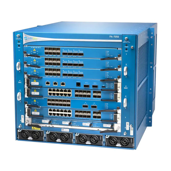
Front Panel (AC) Front Panel (AC) Figure 1 shows the front panel of the PA-7050 (AC) platform and Table 1 describes the front panel features. Figure 1. PA-7050 Front Panel (AC) PA-7050-FAN PA-7050 PA-7050-FAN POWER POWER FAULT FAULT PA-7000-BLANK PA-7000-BLANK... - Page 7 Front Panel (AC) Table 1. PA-7050 (AC) Front Panel Features Item Description Exhaust Fan Tray Hot-swappable exhaust fan tray that provides ventilation and cooling for the chassis. The fan tray is interchangeable and can be installed on either side of the chassis to perform exhaust or air intake functionality.
- Page 8 Provides AC power to the chassis. The chassis should always have all four power supplies operational at all times. DC power supplies are also available for the PA-7050 and are installed in the same power supply slots as the AC power supplies. When DC power supplies are installed, the back panel AC inlets and switches are not functional and must be covered with the provided cover plate.
-
Page 9: Back Panel (Ac)
Back Panel (AC) Back Panel (AC) Figure 2 shows the back panel of the PA-7050 (AC) platform and Table 2 describes the back panel features. Figure 2. Back Panel (AC) Palo Alto Networks Overview • 9... -
Page 10: Front Panel (Dc)
25 amps. Front Panel (DC) Figure 3 shows the front panel of the PA-7050 (DC) platform. The only difference between the front panel AC platform and the front panel DC platform is that the DC platform uses four DC power supplies instead of four AC power supplies. - Page 11 Front Panel (DC) Figure 3. Front Panel (DC) PA-7050-FAN PA-7050 PA-7050-FAN POWER POWER FAULT FAULT PA-7000-BLANK PA-7000-BLANK PA-7000-BLANK PA-7050-SMC CONSOLE HSCI-A HSCI-B HA1-A HA1-B PA-7000-BLANK PA-7000-BLANK PA-7000-20G-NPC ACTIVITY POWER ACTIVITY POWER ACTIVITY POWER ACTIVITY POWER FAULT FAULT FAULT FAULT PA-7000-AMC-1TB...
-
Page 12: Back Panel (Dc)
Back Panel (DC) Figure 4 shows the back panel of the PA-7050 (DC) platform. The only differences between the back panel AC platform and the back panel DC platform is that the DC platform will have a cover plate over the AC inlets and power switches. -
Page 13: Pa-7050 Modules And Interface Card Overview
PA-7050 Modules and Interface Card Overview This chapter describes the PA-7050 firewall modules and the interface cards that can be installed and are serviceable. The minimum cards that must be installed to operate the PA-7050 firewall is one Switch Management Card (SMC), one Network Processing Card (NPC), and one Log Processing Card (LPC). -
Page 14: Switch Management Card (Smc)
/192.168.1.1. For example, change the management computer IP address to 192.168.1.2, connect directly to the MGT port and browse to the MGT IP address. You can also SSH to 192.168.1.1. The default login name and password is admin/admin. 14 • PA-7050 Modules and Interface Card Overview Palo Alto Networks... - Page 15 SMC card release Levers, screws, and lever release latches used to install and remove the SMC card. The lever release on each side slides upward to release the hardware lever. Palo Alto Networks PA-7050 Modules and Interface Card Overview • 15...
-
Page 16: Interpreting The Smc Leds
Green All AC or DC power supplies are operating normally. (Power One or more AC or DC power supplies has failed. Supply) 16 • PA-7050 Modules and Interface Card Overview Palo Alto Networks... -
Page 17: Network Processing Card (Npc)
Network Processing Card (NPC) The Network Processing Card (NPC) provides data traffic connectivity for the PA-7050 firewall. You can install up to six NPCs to expand system capacity. When viewing the NPC cards from the web interface at Network > Interfaces, the NPCs will be organized by slot and will then have an icon to expand the slot to show all ports on the NPC. -
Page 18: Npc Component Descriptions
Table 9. Functions and States of the NPC LED Dashboard State Description Green Card is powered. Power is off. Green Card is operating normally. (STATUS) Yellow Card is booting up. 18 • PA-7050 Modules and Interface Card Overview Palo Alto Networks... -
Page 19: Log Processing Card (Lpc)
The Log Processing Card (LPC) is a dedicated card with a processor, memory, and storage drives used to handle all logging for the PA-7050 firewall. The LPC contains four Advanced Mezzanine Cards (AMCs) used as a carrier for each drive. -
Page 20: Lpc And Amc Component Descriptions
LEDs used for drive activity, drive failures, and power. If there is a hardware issue with the LPC, the LOG LED on the Switch Management Card (SMC) will change to red and the system logs can also be checked for status. 20 • PA-7050 Modules and Interface Card Overview Palo Alto Networks... - Page 21 Blinks green when there is activity on the drive. No activity or powered off. Fault The drive is missing or faulty. No fault or powered off. POWER Green The drive is powered. Power is off. Palo Alto Networks PA-7050 Modules and Interface Card Overview • 21...
- Page 22 Log Processing Card (LPC) 22 • PA-7050 Modules and Interface Card Overview Palo Alto Networks...
-
Page 23: Installing The Hardware
Chapter 3 Installing the Hardware This chapter describes the steps needed to install the PA-7050 firewall in a standard 19” 2-post or 4-post equipment rack. It is important that the steps are followed in order, which includes: installing the chassis in an equipment rack, installing the three mandatory cards required for the chassis to operate (after the chassis is racked), and then connecting power to the chassis. -
Page 24: Equipment Rack Installation
Wear the provided Electrostatic Discharge strap when installing components or servicing the PA-7050 hardware. Equipment Rack Installation This section describes the steps needed to install the PA-7050 firewall in a 2-post or 4-post standard 19” equipment rack. Please read the cautions, warnings, and safety guidelines located in each section. •... -
Page 25: 2-Post Rack Installation
2-Post Rack Installation This section describes the required steps to install the PA-7050 firewall in a 2-Post rack. Note: The PA-7050 chassis and the front slot cards (SMC, LPC, NPC) ship in separate boxes and it is recommended that you install the cards after the chassis is rack mounted. -
Page 26: 4-Post Rack Installation
SM C 4-Post Rack Installation The PA-7050 has removable rack mount brackets on each side that can be placed in a 2-post mid-mount or 4-post front mount configuration. The chassis ships in the 2-post position, so for a 4-post installation, the brackets will need to be re-positioned as described in the following section. - Page 27 Remove the front brackets (A and B) and rear brackets (C and D) from the chassis as shown in Figure 12. Store the rear brackets because they are not needed for a 4-post installation. Figure 12. PA-7050 Front and Rear Bracket Removal Remove Back Brackets...
- Page 28 Equipment Rack Installation Swap the front brackets, so the rack mount screw holes are now on the front of the chassis as shown in Figure 13. Use 25 screws to attach each bracket to the chassis in the front position. Figure 12 shows that brackets A and B are swapped.
- Page 29 Equipment Rack Installation (Optional) If NEBs compliance is required in your region, install a PA-7050 4-post rack mount shelf. Lift the device and position it in the rack aligning the chassis on top of the shelf. It is recommended that two people perform this function using a mechanical equipment lift.
-
Page 30: Install The Mandatory Front Slot Cards
Install the Mandatory Front Slot Cards The PA-7050 requires a minimum of three cards that are installed in the front slots of the chassis. These cards are shipped separately from the chassis and include the following: The Switch Management Card (SMC) provides management connectivity to the chassis and HA connectivity;... -
Page 31: Install The Log Processing Card (Lpc)
LPC should be installed in the chassis first and then the AMC/Drives can then be installed into the LPC. When the PA-7050 is initially installed, you must allow enough time for drives to be formatted and put into the RAID configuration before traffic can be processed and logged. The chassis will operate with one drive, but there will be no drive redundancy. - Page 32 Install the Mandatory Front Slot Cards Attach the provided ESD strap to your wrist and plug it into one of the ESD ports located on the front of the chassis. The ESD ports are located along the bottom row of the chassis and you will see three ports, any of which can be used.
- Page 33 Install the Mandatory Front Slot Cards Install each of the four AMC/Drives into the four slots on the LPC. Figure 17 shows how an AMC/ Drive is installed. Ensure that the handle on the front of each AMC/Drive is pulled outward to the unlocked position before sliding it into the LPC.
-
Page 34: Install A Network Processing Card (Npc)
“Install an NPC in an HA Configuration” on page 36 Install an NPC in a Single Chassis This topic describes the required steps to install an NPC in a single PA-7050. NPCs can be installed in slots 1,2,3,5,6, and/or 7. - Page 35 Install the Mandatory Front Slot Cards Figure 18. Installation and Removal of the SMC and NPC Cards P A -7 05 0 SM C PA-7 050- SMC SM C PA-7 000- 20G -NPC NPCs can be installed in slots 1,2,3,5,6, and/or 7. Install blank slot covers.
- Page 36 HA pair. Important: When installing a new NPC in a PA-7050, the HA software will manage how the NPC is brought up. When you insert the cards into each chassis, it will stay in a disabled state. This will ensure that the NPC does not initiate and start passing traffic until both devices in the HA pair are ready to use the NPCs.
-
Page 37: Connect Power
“Connect DC Power” on page 39 Connect AC Power When connecting the PA-7050 to power, it is recommend that 240V circuits are used and that each pair of AC power supplies is on a different circuit. During normal operation, all four power supplies should be connected to provide redundancy. - Page 38 Connect Power Connect the two post lug connector to the two post lugs on the chassis using the provided star washer and nut and then torque the nuts to 50 in-lbs. Ground Grounding lugs on the back of the chassis. Connect the first two power supplies to a 240V 20 amp AC power source using the provided power cords and then connect the second two power supplies to a difference 240V 20 amp AC power circuit.
-
Page 39: Connect Dc Power
CAUTION: For the DC input circuit, make sure there is a 60 amp circuit breaker, minimum 48VDC, and double pole on the input to the DC power. The power cables used to connect DC power is provided with the PA-7050 firewall. To connect DC power: Use the provided two post copper grounding lug and crimp it to a 6 AWG cable of the correct length that connects to your ground source. -
Page 40: Connect Cables
Red (+) Connect Cables Figure 21 shows the PA-7050 cable connections. For details on the front slot cards, see “PA-7050 Modules and Interface Card Overview” on page 13. When using DC power supplies, the DC power cables will be connected at the front of the DC power supplies. - Page 41 Connect Cables Figure 21. PA-7050 Cable Connections PA-7050 Management Console HA1 Backup HA2/HA3 HA2/HA3 QSFP QSFP Network Network SFP+ Palo Alto Networks Installing the Hardware • 41...
-
Page 42: Verify The Lpc And Npc Configuration
To view the status of the RAID configuration, run the following command: admin@PA-7050> show system raid detail Confirm that at least one RAID 1 pair shows Available, which indicates that a drive pair is ready and the LPC can process and receive logs. The initial formatting to ready the drives should take approximately 3-4 minutes. -
Page 43: Verify The Npc Configuration
Verify the NPC configuration When the PA-7050 is first installed, all NPC slots are ready to use. If you are working with an existing configuration, you may want to check the slot status before adding a new NPC. In HA configuration, the NPC will stay in a disabled state until a matching NPC is installed. - Page 44 Verify the LPC and NPC Configuration 44 • Installing the Hardware Palo Alto Networks...
-
Page 45: Maintaining The Hardware
Chapter 4 Maintaining the Hardware This chapter describes the steps required to replace serviceable hardware components on the PA-7050 firewall. For an overview of each PA-7050 hardware component and details on interpreting LEDs for troubleshooting purposes, see the “PA-7050 Modules and Interface Card Overview” on page 13. -
Page 46: Dc Power Related Cautions/Warnings
(il peut en comporter plusieurs). WARNING: (PA-7050 Firewall) When removing a fan tray, it is recommended that you first pull the fan tray out one inch and then wait 5-10 seconds before extracting the entire fan tray. - Page 47 – The DC supply source must be located within the same premises as this equipment. – The battery returns of the PA-7050 firewall must be connected as either DC-C or DC-I. Switching or disconnecting devices must not be in the earthed circuit conductor between the DC source and the point of connection of the earthing electrode conductor.
-
Page 48: Replace An Ac Or Dc Power Supply
Replace an AC or DC Power Supply The PA-7050 firewall can use four AC or four DC power supplies that are inserted in the front of the chassis. When using DC power supplies, the AC power inlets and switches on the back of the device are not functional and must be covered with the provided cover plate. - Page 49 Replace an AC or DC Power Supply Pull the power supply lever from the top center of the power supply to disengage it from the chassis and then slide the power supply out of the chassis using the handle as shown in Figure 22. Figure 22.
-
Page 50: Replace A Dc Power Supply
Before servicing the hardware, read the information in “Cautions and Warnings” on page 43. The PA-7050 can be configured with four serviceable hot-swappable DC power supplies located on the front of the chassis. To locate the failed power supply, view the system logs or check the LEDs located on each power supply. -
Page 51: Replace An Amc/Disk Drive
Before servicing the hardware, read the information in “Cautions and Warnings” on page 43. The PA-7050 firewall has a dedicated Log Processing Card (LPC) that contains four disk drives. The disk drives are connected to the LPC using an Advanced Mezzanine Card (AMC) and each AMC contains one 2.5”... - Page 52 Replace an AMC/Disk Drive total of 2 terabytes of storage. If a drive fails in one of the RAID 1 pairs, when you order a replacement from Palo Alto Networks or your reseller, you will receive a new AMC that will also contain a new drive.
- Page 53 Figure 25. Unlock and Lock the AMC/Disk Drive Pull handle out to unlock, push in to lock. Figure 26. Replace a PA-7050 AMC/Disk Drive Install the new AMC/Disk drive by gently sliding the drive into the AMC slot and then push the release handle all the way in to lock the AMC in place.
-
Page 54: Replace A Fan Tray
Replace a Fan Tray Replace a Fan Tray Before servicing the hardware, read the information in “Cautions and Warnings” on page 43. The following procedures describe the required steps to replace a fan tray. Please read the following cautions and warnings related to the fan tray and read the “Cautions and Warnings” on page 43. CAUTION: You can replace a fan tray while the firewall is powered on;... - Page 55 Replace a Fan Tray Figure 27. Loosening the Thumb Screws to Unlock the Fan Tray Open Position Beware of spinning fans. Grasp the fan tray handles and pull the tray out about two inches. After all fans have stopped spinning, remove the fan tray from the chassis. Install the new fan tray by sliding the tray into the chassis, ensuring it is seated properly.
-
Page 56: Replace The Air Filter
Replace the Air Filter Figure 28. Installing the Fan Tray and Securing it to the Chassis Lock Position Replace the Air Filter There is one air filter located on the right of the chassis (intake side). This filter should be inspected on a periodic basis and can be pulled out and inserted without setting off any alarms. -
Page 57: Replace Front Slot Cards
Replace Front Slot Cards This section describes the steps needed to replace a failed front slot card. At minimum, the PA-7050 must have one SMC, one LPC, and at least one NPC card. If the SMC or LPC card fails, the chassis will not operate, so it is recommended that you use High Availability (HA) for full redundancy. -
Page 58: Replace A Switch Management Card (Smc)
Replace Front Slot Cards Replace a Switch Management Card (SMC) The Switch Management Card (SMC) is required to operate the chassis. If the SMC fails, the LPC and NPC cards will power down and the chassis will reboot and will try to recover the SMC. If the chassis is restarted more than 3 times in 30 minutes, it will enter maintenance mode at which time it should be powered off until the SMC can be replaced. -
Page 59: Replace A Log Processing Card (Lpc)
Replace Front Slot Cards Remove the new SMC card from the anti-static bag and slide it into slot 4 ensuring that the handles are in the open position. When the card is about 1/4” from being fully inserted, adjust the levers to align with the chassis and then close the levers to seat the card in place. -
Page 60: Replace A Network Processing Card (Npc)
Replace Front Slot Cards the outer release leave to pull the LPC out of the chassis as shown in Figure 31. Note: The LPC uses a double lever on each side of the card. After loosening the thumb screws, you must pull the inner lever toward you to unlock the outer lever from the chassis and then pull the outer lever to release the card from the chassis. - Page 61 “Replace a Network Processing Card in a HA Configuration” on page 60 Replace a Network Processing Card in a Single Chassis This topic describes the steps required to replace a Network Processing Card (NPC) in a single PA-7050 firewall. To replace an NPC: First verify the status of the NPC that is having a problem.
-
Page 62: Front Card Slot States
PA-7050 HA configuration. As with all Palo Alto Networks firewalls, the hardware must match in both devices in the HA configuration. With the PA-7050, it is also required that all cards installed in the front slots are the same on both devices in the HA pair. The PAN-OS software is designed to allow the insertion of new cards (NPCs) without causing a failover. -
Page 63: Front Card Slot States
Front Card Slot States The following table describes the possible states that a PA-7050 slot can be in as well as the states of an installed card. To view slot status from the web interface, select Network > Interfaces and the slot status will be shown to the right of the slot number. -
Page 64: Npc Troubleshooting Commands
Replace Front Slot Cards NPC Troubleshooting Commands Table 16 describes common commands that you can use to troubleshoot NPC issues: Table 16. CLI Commands to Troubleshoot NPC Issues Purpose Command Show the status of a slot. Run the following to view all of the slots: show chassis status To view the status of one slot run: show chassis status slot slot-number... -
Page 65: Chapter 5 Specifications
Specifications This chapter provides specifications for the PA-7050 firewall. For information on the modules and interfaces that can be installed in the PA-7050, see “PA-7050 Modules and Interface Card Overview” on page 13. The following topics describe the PA-7050 specifications: •... - Page 66 “Electrical Specifications and Power Cords” on page 65. Interface Specifications Table 18 lists the interfaces for the PA-7050. When a PA-7050 is fully loaded, the front cards slots will contain one SMC, one LPC, and up to six Network Processing Cards (NPCs). In a fully loaded chassis, you would multiply the NPC numbers in the following table by six.
-
Page 67: Electrical Specifications
• PA-7050 with DC power supplies—(-40 to -60VDC, 60A) Power Cord Types The PA-7050 firewall ships with four AC or four DC power supplies and four power cords. The DC configuration supports one type of DC power cord (first item in the following table) that you terminate to fit your power source. -
Page 68: Environmental Specifications
Environmental Specifications Environmental Specifications Table 19 lists environmental specifications for the PA-7050. Table 19. Environmental Specifications Specification Description Operating temperature range 0° to 50° C. (32°F to 122°F) Storage temperature range -20° to 70° C. (-4°F to 158°F) Humidity 5% to 90% non-condensing... -
Page 69: Compliance Statement
“VCCI Statement” on page 68 • “BSMI EMC Statement” on page 68 NEBS Requirements This section describes the Network Equipment Building System (NEBS) requirements for the PA-7050 firewall. • The device is intended to be installed in a Network Telecommunication Facilities (Central Office) as part of a Common Bonding Network (CBN) or Isolated Bonding Network (IBN). -
Page 70: Vcci Statement
VCCI Statement VCCI Statement This section provides the compliance statement for the Voluntary Control Council for Interference by Information Technology Equipment (VCCI), which governs radio frequency emissions in Japan. The following information is in accordance to VCCI Class A requirements: Translation: This is a Class A product.
Need help?
Do you have a question about the PA-7050 and is the answer not in the manual?
Questions and answers