Sign In
Upload
Download
Table of Contents
Contents
Add to my manuals
Delete from my manuals
Share
URL of this page:
HTML Link:
Bookmark this page
Add
Manual will be automatically added to "My Manuals"
Print this page
×
Bookmark added
×
Added to my manuals
Manuals
Brands
Simrad Manuals
GPS
P2005
Operator's manual
Simrad P2005 Operator's Manual
Hide thumbs
1
2
3
4
5
6
Table Of Contents
7
8
9
10
11
12
13
14
15
16
17
18
19
20
21
22
23
24
25
26
27
28
29
30
31
32
33
34
35
36
37
38
39
40
41
42
43
44
45
46
47
48
49
50
51
52
53
54
55
56
57
58
59
60
61
62
63
64
65
66
67
68
page
of
68
Go
/
68
Contents
Table of Contents
Bookmarks
Table of Contents
Table of Contents
Introduction
About this Unit
Page Layout
Position Quality
Card Reader
Basic Operation
Turning the Unit on
Menu Overview
Backlight Settings
Man over Board
Simulator Mode
Screen Capture
Pages
Selecting a Page
Missing or Faulty Data
Customizable Data Fields
Default Pages
Manage Waypoints and Routes
Manage Waypoints
Manage Routes
Importing Routes and Waypoints
Exporting Waypoints and Routes
Software Setup
Software Setup Overview
Introduction to Lightweight Ethernet
First Time Startup
Software Setup Sequence
The Settings Dialog
System Settings
Page Settings
Trip Log Settings
AIS Settings
GNSS Settings
Navigation Settings
Units Settings
Local Port Setup
Calibration
Network Settings
Maintenance
Preventive Maintenance
Cleaning the Display Unit
Restoring Factory Default Settings
Backup and Restore of System Data
Software Updates
Alerts
Type of Alerts
Alert Notifications
Alert Dialogs
External Bridge Alert Systems
Alphabetic Alert List
Appendix
Menu Overview
Terms and Abbreviations
Icons
Supported Data
LWE Transmission Groups
Advertisement
Quick Links
1
About this Unit
2
System Settings
3
Gnss Settings
Download this manual
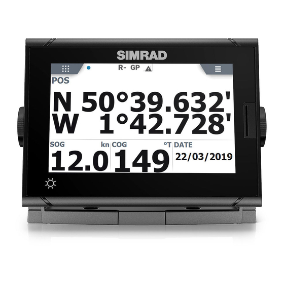
P2005 / P3007
Operator Manual
ENGLISH
www.navico.com/commercial
Table of
Contents
Previous
Page
Next
Page
1
2
3
4
5
Advertisement
Table of Contents
Need help?
Do you have a question about the P2005 and is the answer not in the manual?
Ask a question
Questions and answers
Subscribe to Our Youtube Channel
Related Manuals for Simrad P2005
GPS Simrad P3007 Operator's Manual
(68 pages)
GPS Simrad MX525A Manual
Simrad mx525a dgps receiver manual (34 pages)
GPS Simrad GO7 Getting Started
(40 pages)
GPS Simrad GO XSE Operator's Manual
(162 pages)
GPS Simrad GO7 Installation Manual
(56 pages)
GPS Simrad CX34 Manual
Navstation (218 pages)
GPS Simrad ce32 mkii User Manual
Dgps (130 pages)
GPS Simrad CP42 User Manual
(148 pages)
GPS Simrad GO XSE Getting Started
(41 pages)
GPS Simrad CP33 Manual
(154 pages)
GPS Simrad NSX Installation Manual
(32 pages)
GPS Simrad NSS Series Quick Start Manual
(9 pages)
GPS Simrad GN33 Manual
(152 pages)
GPS Simrad NSO evo2 Quick Start Manual
(9 pages)
GPS Simrad CA42 Manual
(180 pages)
GPS Simrad Shipmate GN30 mkII Operator's Manual
(103 pages)
This manual is also suitable for:
P3007
Table of Contents
Print
Rename the bookmark
Delete bookmark?
Delete from my manuals?
Login
Sign In
OR
Sign in with Facebook
Sign in with Google
Upload manual
Upload from disk
Upload from URL


Need help?
Do you have a question about the P2005 and is the answer not in the manual?
Questions and answers