Snorkel TM12 Series Operator's Manual
Hide thumbs
Also See for TM12 Series:
- Service and parts manual (90 pages) ,
- Service manual (107 pages) ,
- Operator's manual (52 pages)
Table of Contents
Advertisement
Quick Links
Advertisement
Table of Contents

Related Manuals for Snorkel TM12 Series


Summary of Contents for Snorkel TM12 Series
- Page 1 OPERATOR’S MANUAL Part Number 8210027 May 2010 Serial number 53578 and after...
- Page 2 The aerial platform is not electrically insulated. Death or serious injury will result from contact with, or inadequate clearance from, an energized conductor. Do not go closer than the minimum safe approach distance as defined by the Minimum Safe Approach Distance section in Chapter 3–Safety. Regard all conductors as energized.
-
Page 3: Table Of Contents
Table of Contents Electrical Danger ......Inside Front Cover Ground Operation Button ........15 California Proposition 65 ....Inside Front Cover Platform Raise/Lower Switch ........15 Upper Controls ............15 Chapter 1 – Introduction Emergency Stop Button ........16 Drive Select Button ..........16 Aerial Platform Features ..........1 Platform Select Button ..........16 Options ...............1 Joystick ..............16... - Page 4 Table of Contents Chapter 10 – Stowing and Transporting Chapter 11 – Emergency Operation Stowing ..............33 Emergency Lowering ..........37 Transporting .............33 Towing ..............37 Lifting With a Forklift ..........33 Driving ..............33 Chapter 12 – Troubleshooting Winching ...............34 Troubleshooting Chart ..........39 Hoisting ..............34 Securing for Transport ..........35 Appendix A –...
-
Page 5: Chapter 1 - Introduction
Additional copies of this manual may be ordered from Training is essential and must be performed by a quali- Snorkel. Supply the model and manual part number from fied person. Become proficient in knowledge and actual the front cover to assure that the correct manual will be operation before using the aerial platform on the job. -
Page 6: Maintenance
A reprint of the “Manual of Responsibilities for Dealers, federal law. Owners, Users, Operators, Lessors and Lessees of ANSI/SIA A92.6-2006 Self-Propelled Elevating Work Platforms” is available from Snorkel dealers or from the Maintenance factory upon request. Every person who maintains, inspects, tests, or repairs the aerial platform must be qualified to do so. -
Page 7: Chapter 2 - Specifications
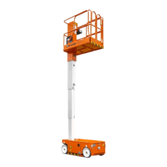
Chapter 2 – Specifications Component Identification Operator’s Manual Upper Controls Platform Mast Tie-Down/Lift Lugs Battery Charger Front Rear Charger Outlet Emergency Plug Lowering Knob Battery Charger Rear Front Indicator Left Side Chassis Lower Controls Battery Tray Batteries Battery Disconnect Hydraulic Tray Inside Tray Hydraulic Reservoir Inside Tray... -
Page 8: General Specifications
Chapter 2 – Specifications General Specifications Aerial Platform Drive System Working height 18′ 6″ (5.6 m) Standard Two wheel drive Maximum platform height 12′ 6″ (3.8 m) Gradeability 25% (14°) Minimum platform height 19″ (48.3 cm) Maximum drive height 12′ (3.6 m) Turning radius Parking brake 2 wheel spring applied... -
Page 9: Chapter 3 - Safety
Chapter 3 – Safety Minimum Safe Approach Distance Knowledge of the information in this manual, and proper training, provide a basis for safely operating the aerial plat- Minimum safe approach distances to energized power form. Know the location of all controls and how they oper- lines and their associated parts must be observed while ate to act quickly and responsibly in an emergency. -
Page 10: Prestart Inspection
Chapter 3 – Safety Prestart Inspection chassis or platform. Allow sufficient room and time to stop movement to avoid contact with structures Perform a prestart inspection before each shift as de- or other hazards. scribed in Chapter 8. Do not use the aerial platform on the job unless you are trained and authorized to do so. -
Page 11: Tip-Over And Falling Hazards
Snorkel. not given immediately. In case of injury by escaping hydraulic fluid, seek medical attention at once. -
Page 12: Placards And Decals
Chapter 3 – Safety Placards and Decals The aerial platform is equipped with placards and decals that provide instruction for operation and accident preven- tion. Do not operate the aerial platform if any placards or decals are missing or not legible. TM12 –... -
Page 13: Chapter 4 - Safety Devices
Chapter 4 – Safety Devices This aerial work platform is manufactured with safety devices, placards, and decals to reduce the likelihood Emergency of an accident. Stop Button • For the safety of all personnel, do not disable, modify, or ignore any safety device. •... -
Page 14: Lowering Alarm
Chapter 4 – Safety Devices If the chassis is tilted more than two degrees side-to-side The entry chain allows for access to the platform. After or front-to-rear, the drive and lift functions will not operate entering the platform the chain must be securely fastened and an alarm will sound. -
Page 15: Chapter 5 - Gauges And Displays
Chapter 5 – Gauges and Displays For example, if pressing the switch slowly three times The aerial platform is equipped with an hour meter and displays “10” followed by “40” and then “hr” after the a battery charge indicator to monitor the condition of the third time, the accumulated aerial platform operating machine before and during operation. - Page 16 Chapter 5 – Gauges and Displays TM12 – 8210027...
-
Page 17: Chapter 6 - Batteries
Chapter 6 – Batteries The battery tray at the rear of the chassis, contains four, Charging 220 amp, 6 volt batteries to operate the aerial platform The aerial platform is equipped with a 20 amp automatic drive and control systems. battery charger that will completely recharge the batter- ies and turn off after the charge cycle is completed. - Page 18 Chapter 6 – Batteries 6. Plug the battery charger into a properly grounded 8. Leave the battery charger plugged in until it shuts outlet (115 volt AC, 60 Hz) using a 3 conductor, 12 itself off. gauge or larger extension cord. The extension cord must be as short as possible (no longer than 50′) and Note in good electrical condition.
-
Page 19: Chapter 7 - Controls
Chapter 7 – Controls Danger Pinch points may exist between moving components. Ground Operation Button Death or serious injury will result from becoming Emergency Stop Button trapped between components, buildings, structures, or other obstacles. Make sure all personnel stand clear while operating the aerial platform. •... -
Page 20: Emergency Stop Button
Chapter 7 – Controls The following controls are located on the upper control • Press the platform select button to use the joystick panel: to operate platform functions. • Emergency stop button Movement of the joystick in a given direction produces •... -
Page 21: Chapter 8 - Prestart Inspection
Chapter 8 – Prestart Inspection Electrical System Potential service and safety problems may be detected by inspecting the aerial platform. This chapter includes Electrical power is supplied from four 220 amp hour, 6 information on properly inspecting the aerial platform and volt batteries. -
Page 22: Battery Terminals
Chapter 8 – Prestart Inspection 4. Replace the caps on the battery. The caps must be in Use the following procedure to properly block the mast. place and tight during machine operation and battery charging. 1. Remove all tools and material from the platform. Battery Terminals 2. -
Page 23: Hydraulic System
Chapter 8 – Prestart Inspection Hydraulic System Hoses, Tubes, and Fittings To inspect the hoses, tubes, and fittings: Hydraulic power is supplied from a single stage hydraulic pump with a 4 horsepower DC electric motor. 1. Inspect all hydraulic hoses, tubes, and fittings for wear, leakage, or damage (refer to Figure 8.6). -
Page 24: Parking Brakes
Chapter 8 – Prestart Inspection 2. Check the wheels to see that the fasteners are in Danger place and are not damaged or loose. Pinch points may exist between moving components. Death or serious injury will result from becoming Parking Brakes trapped between components, buildings, structures, Inspect the brake shoes to make sure they fully engage or other obstacles. -
Page 25: Structures
Chapter 8 – Prestart Inspection 3. Release the knob to stop. Fasteners To inspect the component fasteners: 4. Make certain the knob is fully released after lowering the platform. 1. Visually inspect all fasteners to see that none are missing or loose. Structures 2. -
Page 26: Lanyard Anchors
5. Test the operation of each control in both directions from the upper controls. Placard and decal kits are available from Snorkel. • Press the drive select button and test the operation The safety related placards and decals are illustrated on of the joystick in both directions. - Page 27 Chapter 8 – Prestart Inspection 101250-000 66556-000 101250-000 66556-001 66556-000 66568-000 101250-000 066555-901 66556-001 Serial Number Placard Inside Tray Right Side 101250-000 Serial Number Placard TM12 – 8210027...
- Page 28 Chapter 8 – Prestart Inspection 66556-000 66556-000 66556-000 114005-950 66552-000-00 114005-950 066556-001 Left Side 66556-001 TM12 – 8210027...
- Page 29 Chapter 8 – Prestart Inspection 101250-000 101250-000 66554-000 66550-001 66554-000 101250-000 62562-001 66556-000 66550-001 Left Side 62562-001 66556-000 TM12 – 8210027...
- Page 30 Chapter 8 – Prestart Inspection TM12 – 8210027...
-
Page 31: Prestart Inspection Checklist
Chapter 8 – Prestart Inspection Prestart Inspection Checklist Item Inspect For Operator’s Manual In place, all pages readable and intact Electrical System Battery fluid level Proper level Battery terminals Clean, connectors tight Batter charger Proper operation Cables and wiring harness No wear or physical damage Hydraulic System Fluid level... - Page 32 Chapter 8 – Prestart Inspection TM12 – 8210027...
-
Page 33: Chapter 9 - Operation
Chapter 9 – Operation Preparing for Operation The aerial platform may be operated from either the lower or upper controls. Make certain the batteries are charged and the charger is unplugged before operating the aerial platform. Use the following procedure to prepare the aerial platform Danger for operation. -
Page 34: Upper Controls
Chapter 9 – Operation Upper Controls Use the following procedure to operate the drive func- tions. The upper controls may be used for driving the aerial platform and positioning the platform while on the job. 1. Press the drive select button (refer to Figure 9.2). Before operating from the upper controls, properly set 2. -
Page 35: Platform
Chapter 9 – Operation Swing-Out/Slide-Out Trays Note Holding the steer switch down too long may result in The lower controls and hydraulic components are en- a sharp turn. This is especially true when driving and closed in a swing-out tray (refer to Figure 9.4) on the right steering at the same time. - Page 36 Chapter 9 – Operation TM12 – 8210027...
-
Page 37: Chapter 10 - Stowing And Transporting
Chapter 10 – Stowing and Transporting • Making sure that all manufacturer’s instructions To prevent unauthorized use and damage, properly stow and warnings, regulations and safety rules of their the aerial platform at the end of each work day. It must also be properly stowed while transporting. -
Page 38: Winching
Chapter 10 – Stowing and Transporting 4. Drive the machine to the foot of the loading ramp with Compression Nut the front wheels nearest the ramp. 5. Verify that the machine wheels, loading ramps, and transport vehicle are aligned. 8 ¾″ 9″... -
Page 39: Securing For Transport
Chapter 10 – Stowing and Transporting from falling out under a slack line condition may also Warning be used. The potential for an accident increases when the aerial platform is lifted using improper equipment Do not run the sling cable through the lifting lugs. and/or lifting techniques. - Page 40 Chapter 10 – Stowing and Transporting TM12 – 8210027...
-
Page 41: Chapter 11 - Emergency Operation
Chapter 11 – Emergency Operation If the main hydraulic system fails: 5. Make certain the knob is fully released and the emer- gency lowering valve is fully closed before operating the aerial platform. • The aerial platform may be lowered using the emer- gency lowering knob. - Page 42 Chapter 11 – Emergency Operation TM12 – 8210027...
-
Page 43: Chapter 12 - Troubleshooting
Chapter 12 – Troubleshooting action listed, stow the machine and remove it from ser- The troubleshooting chart may be used to locate and vice. Repairs must be made by qualified maintenance eliminate situations where machine operation may be interrupted. If the problem cannot be corrected with the personnel. - Page 44 Chapter 12 – Troubleshooting Symptom Possible Cause Corrective Action Platform will not raise, or raises Emergency lowering knob not prop- Make sure the knob returns to the slower than normal. erly disengaged. normal operating position. Platform capacity has been ex- Remove items from platform to ob- ceeded.
- Page 45 Chapter 12 – Troubleshooting Symptom Possible Cause Corrective Action Hydraulic fluid temperature of Prolonged driving or platform opera- Stop operation until fluid cools. 160°F (71°C) or more. tion. High pressure fluid return to reservoir Remove the kink or twist from the caused by kinked or twisted hose.
- Page 46 Chapter 12 – Troubleshooting TM12 – 8210027...
-
Page 47: Appendix A - Glossary
Although federal regulations, OSHA, ANSI, pothole protection system – a mechanical tip-over prevention system and Snorkel do not require the use of additional fall protection beyond the consisting of skids along the bottom of both sides of the chassis which lower platform guardrails on scissor lift aerial platforms, local, state, or employer as the platform is raised. - Page 48 Appendix A – Glossary TM12 – 8210027...
-
Page 49: Limited Warranty
LIMITED WARRANTY Snorkel warrants each new machine manufactured and sold by it to be free from defects in material and workmanship for a period of one (1) year from date of delivery to a Customer or for one year after the machine has been placed in first service in a Dealer rental fleet, whichever comes first. - Page 50 Local Distributor / Lokaler Vertiebshändler / Distributeur local El Distribuidor local / ll Distributore locale EUROPE, MIDDLE EAST AFRICA & ASIA PHONE: +44 (0) 845 1550 058 FAX: +44 (0) 845 1557 756 NORTH & SOUTH AMERICA PHONE: +1 785 989 3000 TOLL FREE: +1 800 255 0317 FAX: +1 785 989 3070 AUSTRALIA...
Need help?
Do you have a question about the TM12 Series and is the answer not in the manual?
Questions and answers