Table of Contents
Advertisement
ENVELOPE MANAGEMENT
CALIBRATION MANUAL
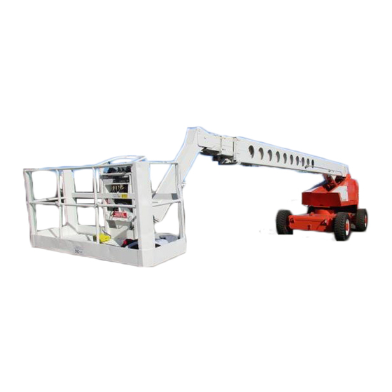
TB 120, PRO 100 & PRO 126
Use this manual to calibrate all PRO 100, PRO 126 and TB 120
machines.
See table of contents for section that is for your machine.
DO NOT attempt to calibrate the EMS system without having first
read and completely understanding the procedures described in this
manual.
ONLY qualified personnel, trained on the EMS , should perform EMS
calibration procedures.
Should there be any question concerning anything covered in this
manual, contact the Snorkel Customer Service Department, telephone
816-364-0317 or for additional information.
Snorkel
P O Box 1160
St Joseph Mo 64502-1160
Phone: 816-364-0317
P/N 0191401
April 1997 - revised September 2000
SYSTEM ( EMS )
MODELS
Printed in the USA
Advertisement
Table of Contents

Subscribe to Our Youtube Channel
Related Manuals for Snorkel PRO 126


Summary of Contents for Snorkel PRO 126
- Page 1 CALIBRATION MANUAL MODELS TB 120, PRO 100 & PRO 126 Use this manual to calibrate all PRO 100, PRO 126 and TB 120 machines. See table of contents for section that is for your machine. DO NOT attempt to calibrate the EMS system without having first read and completely understanding the procedures described in this manual.
- Page 2 1. Fluke 88 or equivalent. 2. Calibration harness - Snorkel part no. 0191008 3. Three prong test plug - Snorkel part no. 0191025 4. Two prong test plug - Snorkel part no. 0191024 5. EZ Cal (when available)
-
Page 3: Table Of Contents
SECTION III CALIBRATION All PRO 100 and PRO 126 machines and TB 120 machines manufactured after September 1994 Joystick calibration – (lift and extend) ....3 - 1 3 - 2 Sensor calibration . - Page 4 5 - 10 5 - 11 Backup EMS errors (TB 120 and PRO 126 only) ... . . 5 - 11 5 - 12 Trouble shooting for system calibration errors ....5 - 13...
-
Page 5: Joystick Calibration - (Lift And Extend)
SECTION I CALIBRATION Use this section to calibrate - TB 120 machines manufactured before September 1994 and have not been updated to three point computers. Before performing the sensor calibration make sure the unit is on a flat, firm and level surface with the turntable in the stowed position, boom over rear axle, counter weight over the steer axle. -
Page 6: Sensor Calibration
SENSOR CALIBRATION: 1. Open junction box on left side of turntable and install calibration harness to all matching numbered terminals. Note: Disconnect EMS harness leads labeled 14, 15, 21 and 22 from proportional control valve. Match numbers and connect the remaining calibration harness leads to proportional control valve. -
Page 7: Full Speed/Half Speed Calibration
RAMP CALIBRATION (Continued): 3. Two (2) short beeps will be heard, indicating that the ramp speed for retract is to be set. To set ramp speed for retract, press the ERROR RESET button the number of times for the desired ramp speed, with one (1) being the minimum ramp or fastest and eight (8) being the maximum ramp or slowest. -
Page 8: Half Speed Calibration
FULL SPEED/HALF SPEED CALIBRATION (Continued): 5. Four (4) beeps will be heard, indicating that the full lower speed is to be set. To set the full lower speed, press the ERROR RESET button the number of times for the desired full speed, with one (1) being the fastest and eight (8) being the slowest. -
Page 9: Valve Calibration
VALVE CALIBRATION: Note: MAKE SURE the hydraulic oil is at operating temperature (80° F.), before calibration. 1. At the ground control, raise the boom to approximately horizontal height with boom partially extended, (two to three feet), to allow for valve calibration. Turn engine “OFF”. -
Page 10: Backup Ems Calibration
BACKUP EMS CALIBRATION: 1. Before calibration, power up the machine. If the calibration data stored in the EMS controller has been calibrated before and is currently within acceptable limits, the system will go to normal operation with SYSTEM NORMAL on. 2. -
Page 11: Calibration
SECTION II CALIBRATION Use this section to calibrate - TB 120 machines manufactured before September 1994 and have updated to three point computers. To determine if machine has been updated, look inside turntable under base boom on right side for angle indicator arm. Before performing the sensor calibration make sure the unit is on a flat, firm and level surface with the turntable in the stowed position, boom over rear axle, counter weight over the steer axle. -
Page 12: Sensor Calibration
SENSOR CALIBRATION: 1. Open junction box on left side of turntable and install calibration harness to all matching numbered terminals. Note: Disconnect EMS harness leads labeled 14, 15, 21 and 22 from proportional control valve. Match numbers and connect the remaining calibration harness leads to proportional control valve. -
Page 13: Ramp Calibration
THINGS THE PRIMARY LOOKS FOR AND THAT THE BACKUP LOOKS FOR PRIMARY LOOKS FOR BACKUP LOOKS FOR 1. JOYSTICK CALIBRATION 1. SENSOR CALIBRATION 2. SENSOR CALIBRATION 2. THREE POINT CALIBRATION 3. THREE POINT CALIBRATION (IF EQUIPPED WITH) After the three (3) calibration data sets are accepted, (joystick, sensor and three point), the system may error out right away. -
Page 14: Full Speed/Half Speed Calibration
FULL SPEED/HALF SPEED CALIBRATION - (Factory set at 1 click): 1. Deflect the Drive joystick forward while pressing and holding the CALIBRATE button firmly. Then turn the power “ON”, (DO NOT start the engine). Wait for approximately two (2) seconds until the SYSTEM NORMAL, CAL MODE and AUTO MODE lights are “ON”. -
Page 15: Half Speed Calibration
HALF SPEED CALIBRATION - (Factory set at 4 clicks): 6. The system will immediately go to half lift speed calibration, three (3) beeps will be heard. Set the half lift speed by pressing the ERROR RESET button the number of times corresponding to the desired speed with one (1) being the fastest and eight (8) being the slowest speed. -
Page 16: Valve Calibration
VALVE CALIBRATION: Note: MAKE SURE the hydraulic oil is at operating temperature (80° F.) before calibration. 1. At the ground control, raise the boom to approximately horizontal height with boom partially extended, (two to three feet), to allow for valve calibration. Turn engine “OFF”. -
Page 17: Backup Ems Calibration
BACKUP EMS CALIBRATION: 1. Before calibration, power up the machine. If the calibration data stored in the EMS controller has been calibrated before and is currently within acceptable limits, the system will go to normal operation with SYSTEM NORMAL on. 2. -
Page 18: Calibration
6. With your right hand, press and hold the CALIBRATE and ERROR RESET buttons located on the backup BDU (the right one) [TB 120 & PRO 126 only]. 7. Release the primary CALIBRATE and ERROR RESET buttons and the toggle switch located between the BDU's with your left hand. - Page 19 JOYSTICK CALIBRATION — (LIFT AND EXTEND) (Continued): 8. Release the backup CALIBRATE and ERROR RESET buttons with your right hand [TB 120 & PRO 126 only]. 9. IMMEDIATELY proceed to the ground station and start the engine. Do not turn the master switch off first.
-
Page 20: Sensor Calibration
3. Lower jib boom fully [PRO 100 & PRO 126 only]. 4. Lower main boom. TB 120 – Lower main boom completely. PRO 100 & PRO 126 only – Lower main boom so that bottom of platform mount frame is approximately 6 inches above the ground. - Page 21 SENSOR CALIBRATION (Continued): 5. Press backup CALIBRATE button. [TB 120 & PRO 126 only] If the data is accepted, there will be two (2) short beeps. One (1) long beep indicates incorrect data has been entered. If one (1) long beep is heard, turn “OFF” the machine and repeat the joystick and sensor calibrations again.
-
Page 22: Ramp Calibration
RAMP CALIBRATION – ( FACTORY SET AT FOUR (4) CLICKS): 1. At ground control, set Platform/Ground Selector switch to GROUND, pull Emergency stop button OUT and turn Master switch ON but do not start engine. 2. Turn the battery disconnect switch on the left side of the turntable to the OFF position. -
Page 23: Speed Calibration Table (Factory Settings)
1 CLICK 1 CLICK 2 CLICKS 2 CLICKS PRO 100 4 CLICKS 1 CLICK 8 CLICKS 4 CLICKS 7 CLICKS 5 CLICKS PRO 126 1 CLICK 1 CLICK 1 CLICK 1 CLICK 2 CLICKS 2 CLICKS Page no. 3 - 6... -
Page 24: Full Speed Calibration
SPEED CALIBRATIONS: FULL SPEED CALIBRATION: 1. At ground control, set Platform/Ground Selector switch to GROUND, pull Emergency Stop button OUT and turn Master switch ON but do not start the engine. 2. Turn the battery disconnect switch on the left side of the turntable to the OFF position. -
Page 25: Half Speed Calibration
HALF SPEED CALIBRATION: 10. The system will immediately go to half lift speed calibration, three (3) beeps will be heard. Set the half lift speed by pressing the ERROR RESET button the number of times corresponding to the desired speed with one (1) being the fastest and eight (8) being the slowest speed. -
Page 26: Valve Calibration
VALVE CALIBRATION: Note: MAKE SURE the hydraulic oil is at operating temperature before calibration. 1. At the ground control, raise the boom to within 30 degrees above horizontal with boom partially extended, (two to three feet), to allow for valve calibration. Turn engine OFF. -
Page 27: Primary And Backup Ems System
SECTION IV GENERAL CALIBRATION NOTES PRIMARY AND BACKUP EMS SYSTEMS: Note: The exact calibration sequence should be followed for any new EMS controller. 1. If the system does not allow a requested calibration procedure, the operator should try to calibrate the previous functions. For example, if the system does not allow Full/Half speed calibration, then start the Ramp speed calibration. -
Page 28: Calibration Overview
CALIBRATION OVERVIEW: The calibration mode is utilized to initialize the complete system or to optimize the vehicle's performance. Complete system calibration is required whenever a system has been installed onto a vehicle. Each individual system calibration routine can be used in the event a component has been replaced or if vehicle application conditions change. -
Page 29: Ramp Calibration Overview
PRIMARY JOYSTICK AND SENSOR CALIBRATION OVERVIEW (Continued): WARNING During sensor calibration, the envelope management system in the primary EMS controller DOES NOT limit the position of the platform. The operator should be careful not to operate the platform outside of the working envelope. Depressing the CALIBRATE button will acknowledge the ECU that the sensor calibration is complete. -
Page 30: Full/Half Speed Calibration Overview
FULL/HALF SPEED CALIBRATION OVERVIEW: To enter Full/Half Speed Calibration mode, the operator must depress the CALIBRATE button and deflect the drive controller forward on power-up. When this is done, the CAL MODE, AUTO MODE and SYSTEM NORMAL indicators will be illuminated, (the CAL MODE indicator will flash three (3) times before remaining lit). -
Page 31: Valve Calibration Overview
VALVE CALIBRATION OVERVIEW: The boom must be retracted well within the high speed operating range and the angle must be less than 30 degrees for this procedure to work, or else the error light will illuminate immediately. It is important to calibrate all functions when in the valve calibration mode. -
Page 32: Ems Calibration Modes & Tables
SYSTEM WAITING JOYSTICK AND SENSOR CALIBRATION RAMP CALIBRATION SPEED CALIBRATION VALVE CALIBRATION PRO 100, PRO 126 & TB 120 AFTER SEPTEMBER 1994 SWITCH CONDITION UPON POWER UP ERROR RESET CALIBRATE CENTER TOGGLE SWITCH BUTTON BUTTON BETWEEN BDU'S POWER UP MODE... -
Page 33: Troubleshooting Description Index
TROUBLESHOOTING DESCRIPTION INDEX 0.0 General Description 1.0 Primary EMS errors during power-up 1.1 All lights, except error light, and alarm flash on, but then error light and alarm remain on - self test fails 1.2 ERROR and CAL MODE light on after self test 1.3 ERROR light on after self test 1.4 All lights flash and error on but no alarm 1.5 Lights and alarm never turn on... -
Page 34: 0.0 General Description
0.0 General Description The envelope management system consists of a primary and a backup set. [PRO 100 has a primary EMS set only]. Each set has its own controller (electronic unit or ECU) and its own boom length and boom angle sensors. BACKUP PRIMARY Primary and backup set location illustration... -
Page 35: Backup Set
BACKUP SET: The TB 120 and the PRO 126 have a backup EMS set. This backup set is active at all times and receives input only from its boom sensors and controls the blocking valves for the lift/lower and extend/retract functions to keep the platform within the backup working envelope. - Page 36 Primary EMS errors during power-up (Continued): The following steps should be followed in order to ensure proper system performance, but the operator has the ability to enter normal system operation using default values. 1.2.1 Press the ERROR RESET button. If the ERROR light is off and the system is operable after releasing the button, then some of stored data is not correct and default data will be used for normal operation.
- Page 37 Primary EMS errors during power-up (Continued): 1.3.3 The error is cleared by pressing the error reset button, but the system errors out again after releasing the reset button. Refer to section 2.0 for trouble shooting. 1.4 All lights, except error light, and alarm flash on first. Then the ERROR light remains on with no alarm.
- Page 38 2.0 Primary EMS errors that occur when joystick is at center This section provides troubleshooting information for the primary EMS errors that occur when the operator is not operating the boom, i.e., the joysticks are not deflected. 2.1 Errors that stop the control system. Error light and alarm will be on. Operator will not be able to move the boom.
- Page 39 Recommend initial value is 0.125v on the Apitech unit and 0.200v on the Celesco unit. Length sensor adjustment is only required IF the initial voltage readings are OUTSIDE the fully retracted and/or fully extended range. PRO 100 & PRO 126 4.865v 4.375v FULLY LIFTED *...
-
Page 40: 3.0 Primary Ems Errors During Normal Operation
Primary EMS errors that occur when joystick is at center (Continued): 2.2.2.2 Sensor error - check the boom length and angle sensors and their connections to the EMS controller. Replace them if necessary. The sensor reading should be within the appropriate ranges as shown in section 2.1.3.3. - Page 41 Primary EMS errors during normal operation (Continued): 3.1.1.2 If the platform continues to move, the operator should not try to activate the system. Turn off the engine immediately. The backup EMS will close the blocking valves to prevent the platform from moving further out of the backup envelope. For such emergency, follow the emergency bleed down procedure.
- Page 42 Primary EMS errors during normal operation (Continued): 3.2.2.4 If all functions move with a 9 volt battery, then reconnect everything and check the voltage going to each solenoid from the EMS controller one at a time. A two prong test lead (part no. 0191024), should be used so voltages can be checked while the solenoid is connected.
-
Page 43: Backup Ems Errors (Tb 120 And Pro 126 Only)
Check the harness connections. Replace it if necessary. 4.0 Backup EMS errors (TB 120 and PRO 126 only) The backup EMS has a secondary (backup) envelope check. If the boom is out of the second envelope (generally 2-3 feet from the primary envelope). - Page 44 Backup EMS errors (TB 120 and PRO 126 only) (Continued): PRO 100 & PRO 126 4.865v 4.375v FULLY LIFTED * TB 120 ANGLE SENSOR 0.352v 0.098v FULLY LOWERED * PRO 100 & PRO 126 1.015v .547v FULLY LOWERED** ** Using Calibration Harness part no. 0191008 (lowered fully) ** Using Calibration Harness part no.
-
Page 45: 5.0 Trouble Shooting For System Calibration Errors
5.0 Trouble shooting for system calibration errors Generally, the operator need not and should not calibrate the control system. However, the valve calibration can be performed if the weather condition changes. The valve calibration is generally calibrated at oil temperature of 30 degrees above outside temperature for best performance. - Page 46 NOTES: Page no. 5 - 14...
Need help?
Do you have a question about the PRO 126 and is the answer not in the manual?
Questions and answers