
Subscribe to Our Youtube Channel
Related Manuals for Snorkel TL37


Summary of Contents for Snorkel TL37
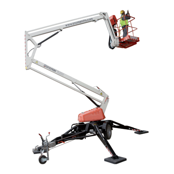
- Page 1 OPERATOR’S MANUAL Part Number 511116-000-EN-A December 2017 Serial number 007625 and after...
-
Page 2: Proposition 65 Warning
The aerial platform is not electrically insulated. Death or serious injury will result from contact with, or inadequate clearance from, an energized conductor. Do not go closer than the minimum safe approach distance as defined by the Minimum Safe Approach Distance section in Chapter 3–Safety. Regard all conductors as energized. -
Page 3: Table Of Contents
Table of Contents Chapter 7 – Controls Electrical Danger ......Inside front cover Proposition 65 Warning ....Inside front cover Lower Controls ............17 Emergency Stop Button ........17 Control Selector/Ground Operation Switch ...17 Chapter 1 – Introduction Platform Raise/Lower Button ........17 Aerial Platform Features ..........1 Outrigger Raise/Lower Button .......17 Options ...............1... - Page 4 Table of Contents Chapter 12 – Troubleshooting Troubleshooting Chart ..........38 Appendix A – Glossary Limitited Warranty TL37J – 511116-000-EN-A...
-
Page 5: Chapter 1 - Introduction
Additional copies of this manual may be ordered from a bottom boom with a tie-rod, a short vertical boom and Snorkel. Supply the model and manual part number a top boom with a telescope section. from the front cover to assure that the correct manual will be supplied. -
Page 6: Operation
The operator must be trained and authorized to per- ANSI/SIA A92.6-2006 Self-Propelled Elevating Work form any functions of the aerial platform. Platforms” is available from Snorkel dealers or from the factory upon request. Operation of the aerial platform must be within the scope of the machine specifications. -
Page 7: Chapter 2 - Specifications
Chapter 2 – Specifications Component Identification Platform Platform Controls Lower/Ground Boom Structure Controls Emergency Lowering Valve Identi cation number plate Outriggers Toeboards Wheels Right Side Emergency Lowering Valve Platform Overload Switch Emergency Lowering Hand Pump Rear Lights Safety Battery Disconnect- Manual Slew Lever Harness... -
Page 8: General Specifications
Chapter 2 – Specifications General Specifications Electrical System Operating Dimensions Energy source 24V battery 4 X 6V Maximum platform height 36’ (11.1m) 225 Ampere hour/ 230V Guard rail height 44.5”(1.13m) mains power/ bi-energy/ Maximum working height 40’(12.23m) petrol & battery power Platform length 47”(1.2m) System voltage... -
Page 9: Chapter 3 - Safety
Chapter 3 – Safety Knowledge of the information in this manual, and proper Danger training, provide a basis for safely operating the aerial The aerial platform is not electrically insulated. Death platform. Know the location of all controls and how they or serious injury will result from contact with, or in- operate to act quickly and responsibly in an emergency. -
Page 10: Operation
Chapter 3 – Safety The welding ground clamp must be attached to the falling or being kicked off the platform. Remove all objects same structure that is being welded. that do not belong in or on the aerial platform. Electrical current flow can be very intense, causing Never steady the platform by positioning it against an- serious internal damage to some components. -
Page 11: Electrical System
If acid contacts your eyes, flush immediately with clear unless the application is approved in writing by Snorkel. water and get medical attention. Do not use the aerial platform as a crane, hoist, jack or... - Page 12 Chapter 3 – Safety TL37J– 511116-000-EN-A...
-
Page 13: Chapter 4 - Safety Devices
Chapter 4 – Safety Devices This aerial work platform is manufactured with safety Push the emergency stop button inward to disconnect devices, placards, and decals to reduce the likelihood power to the upper control circuits. of an accident. Twist and pull the button outward to restore power. For the safety of all personnel, do not disable, modify, Control Select/Ground Operation Switch or ignore any safety device. -
Page 14: Emergency Slew
If the emergency lower is used due to a machine defect, do not use the machine. Contact your local The slew lever for the aerial platform is located on the Snorkel representative. side of the chassis as shown in Figure 4.5. Warning... -
Page 15: Emergency Lowering Hand Pump
Chapter 4 – Safety Devices After emergency lowering, any further powered Top Rail lowering could cause an airlock in the hydraulic system. This could cause the hydraulic operation to fail. Lock Rail Mid Rail Strap All booms must be fully extended/raised, then low- ered before work can recommence. - Page 16 Chapter 4 – Safety Devices TL37J – 511116-000-EN-A...
-
Page 17: Chapter 5 - Gauges And Displays
Chapter 5 – Gauges and Displays Diagnostic Center Display The aerial platform is equipped with several gauges to monitor the condition of the machine before and during The diagnostic center LCD display (refer to Figure 5.2) operation. is located at the lower control station. The LCD display shows: Battery Charge Indicator The battery charger has three LED’s (refer to Figure 5.1) - Page 18 Chapter 5 – Gauges and Displays TL37J – 511116-000-EN-A...
-
Page 19: Chapter 6 - Batteries
Chapter 6 – Batteries The battery tray contains four, 6 volts 225ah batteries. If a battery begins to heat before becoming fully These batteries supply 24 volt DC electrical power to charged, it may be necessary to recharge and dis- operate the aerial platform control systems. - Page 20 Chapter 6 – Batteries TL37J – 511116-000-EN-A...
-
Page 21: Chapter 7 - Controls
Chapter 7 – Controls Danger • Turn the switch to the right to enable lower controls Pinch points may exist between moving components. to work Death or serious injury will result from becoming trapped between components, buildings, structures, • Turn the switch to the left to enable upper controls or other obstacles. -
Page 22: Emergency Stop Button
Chapter 7 – Controls The following are located on the platform control sta- tion: • Emergency Stop Button • Platform Raise/Lower Button • Platform Raise/Lower Levers Platform Raise/Lower Levers Emergency Stop Figure 7.4 – Upper Controls Platform Raise/Lower Platform Levers Raise/Lower Button Figure 7.3 –... -
Page 23: Chapter 8 - Prestart Inspection
Chapter 8 – Prestart Inspection Potential service and safety problems may be detected Warning by inspecting the aerial platform. This chapter includes Batteries give off hydrogen and oxygen that can com- information on properly inspecting the aerial platform and bine explosively. Death or serious injury could result includes a prestart inspection check list at the end of this from a chemical explosion. -
Page 24: Safety Switches
Chapter 8 – Prestart Inspection Note Wheels Use only distilled water when refilling the battery. Tap Check tires are at the correct pressure of 55 psi(3.8 water may contain metallic solids such as iron which can bar) and that the wheel nuts are tightened using the reduce the life of the battery. -
Page 25: Hoses, Tubes, And Fittings
Chapter 8 – Prestart Inspection 1. Unplug the battery disconnect. Caution 2. At the lower controls, twist and pull the emergen- Not all hydraulic fluid is suitable to use in the hydrau- cy stop switch outwards to the ON position. lic system. -
Page 26: Structures
Chapter 8 – Prestart Inspection 2. The emergency lower valves located on the lift cylinders lower the boom when pushed in a slow and controlled manner and the boom movement Top Rail is stoped on releasing the valve. Structures Lock Rail Mid Rail Visually inspect all weldments and related components. -
Page 27: Placards And Decals
4. Replace any missing, damaged, or illegible placards or decals before operating the aerial platform. Placard and decal kits are available from Snorkel. The safety related placards and decals are illustrated on the following pages. - Page 28 Chapter 8 – Prestart Inspection 514020-000 510280-000 510280-000 066552-000 510227-000 Figure 8.7 – Right Side Decals 508508-000 514020-000 010076-001 510227-000 Figure 8.8 – Left Side Decals TL37J – 511116-000-EN-A...
- Page 29 Chapter 8 – Prestart Inspection 510280-000 508711-000 010076-001 510227-000 60-65 514020-000 514020-000 TL37J – 511116-000-EN-A...
- Page 30 Chapter 8 – Prestart Inspection 066552-000 TL37J – 511116-000-EN-A...
-
Page 31: Prestart Inspection Checklist
Chapter 8 – Prestart Inspection Prestart Inspection Checklist Item Inspect For Operator’s Manual In manual holder, all pages readable and intact Electrical System Battery fluid level Proper level Battery terminals Clean, connectors tight Battery charger Proper operation Cables and wiring harness No wear or physical damage Hydraulic System Fluid level... - Page 32 Chapter 8 – Prestart Inspection TL37J – 511116-000-EN-A...
-
Page 33: Chapter 9 - Operation
Chapter 9 – Operation Lower Controls The aerial platform may be operated from either the lower or upper controls. The platform raise and lower functions and the outrigger raise and lower functions can be operated from the lower controls. The lower controls may be used for initial set Danger up of the aerial platform, and for testing and inspection. -
Page 34: Platform
Chapter 9 – Operation Use the following procedure to operate the aerial platform from the upper controls: 1. From the lower controls, twist and pull the emer- gency stop button outward (refer to Figure 9.1). 2. Switch the control select/ground operation switch to the upper controls position. -
Page 35: Electrical Power Outlet
Chapter 9 – Operation When closing the tray cover, reverse the process to lock it in place. Electrical Power Outlet The electrical power outlet has two, 3-prong, 125 volt AC electrical connectors (refer to Figure 9.5). Figure 9.5 – Electrical Power Outlet Power is supplied to the outlet by connecting an exter- nal power source to the power-input connector on the chassis. - Page 36 Chapter 9 – Operation TL37J – 511116-000-EN-A...
-
Page 37: Chapter 10 - Stowing And Transporting
Chapter 10 – Stowing and Transporting To prevent unauthorized use and damage, properly stow The user assumes all responsibility for: the aerial platform at the end of each work day. It must also be properly stowed while transporting. Choosing the proper method of transportation. Stowing Choosing the proper selection and use of transporta- Use the following procedure to properly stow the aerial... -
Page 38: Towing
Chapter 10 – Stowing and Transporting Towing Tow Bar Trailer mounted machines may be safely towed be- Coupling hind a vehicle at a speed set by state traffic regulation or up to 50 mph (80km/h), whichever is the lowest. 13 Pin Hand- Light brake... - Page 39 Chapter 10 – Stowing and Transporting 3. Turn the Control select/ground operation switch to lower controls. 4. Disengage the handbrake and ensure that the jockey wheel directional locking pin is removed. Figure 10.7 – Directional Locking Pin Disengaged 5. Using the 2 hydraulic cylinders on the right side of the chassis (refer to Figure 10.8);...
- Page 40 Chapter 10 – Stowing and Transporting TL37J – 511116-000-EN-A...
-
Page 41: Chapter 11 - Emergency Operation
Chapter 11 – Emergency Operation The aerial platform may be lowered using the emergency lowering slew, lowering valves or hand pump. Danger Slew Lever Pinch points may exist between moving components. Death or serious injury will result from becoming trapped between components. Make sure all person- nel stand clear while lowering the platform with the Slew Lever emergency lowering system. - Page 42 Danger If the emergency lower is used due to a machine defect, do not use the machine. Contact your local Snorkel representative. Warning If the emergency lower is used, the top and bottom booms must be fully extended then fully lowered before work can continue.
-
Page 43: Troubleshooting Chart
Chapter 12 – Troubleshooting The troubleshooting chart may be used to locate and action listed, stow the machine and remove it from ser- eliminate situations where machine operation may be vice. Repairs must be made by qualified maintenance interrupted. If the problem cannot be corrected with the personnel. - Page 44 Chapter 12 – Troubleshooting Symptom Possible Cause Corrective Action Wheels won’t turn when winch- Hand Brake is engaged. Manually release the hand brakes ing or pushing. Battery charger does not indi- No source of power. Make sure power source is plugged in cate a reading when charging and turned on.
- Page 45 Although federal regulations, OSHA, ANSI, stow – to place a component, such as the platform, in its rest position. and Snorkel do not require the use of additional fall protection beyond the platform guardrails on scissor lift aerial platforms, local, state, or employer unrestricted rated work load –...
- Page 47 5. The Customer and Dealer shall not be entitled to the benefits of this warranty and Snorkel shall have no obligations here under unless the “Predelivery and Inspection Record” has been properly com- pleted and returned to the Snorkel Warranty department within fifteen (15) days after delivery of the Snorkel product to the Customer or Dealer’s demonstration/rental fleet.
- Page 48 Confirmation that a qualified technician is available to replace the part and that this person has been ac- cepted by Snorkel to carry out such work under the warranty of the machine. Failure to do this may nullify the warranty.
- Page 49 PURPOSE AND DISCLAIMS ALL LIABILITY FOR INCIDENTAL OR CONSEQUENTIAL DAMAGES, INCLUDING BUT NOT LIMITED TO INJURY TO PERSONS OR PROPERTY. The Customer shall make all warranty claims through Snorkel directly or an Authorised Distributor. If unable to contact the Distributor, contact the Snorkel Service Department for further assistance.
- Page 50 Product Warranty APPEAL The buyer may appeal in writing against a rejected or adjusted claim to Snorkel Warranty Department within a period of 21 days of receiving the rejection or adjustment notice. The appeal should be grounded on express reasons and supported by relevant evidence.
- Page 52 Local Distributor / Lokaler Vertiebshändler / Distributeur local El Distribuidor local / ll Distributore locale EUROPE, MIDDLE EAST AFRICA & ASIA PHONE: +44 (0) 845 1550 058 FAX: +44 (0) 845 1557 756 NORTH & SOUTH AMERICA PHONE: +1 785 989 3000 TOLL FREE: +1 800 255 0317 FAX: +1 785 989 3070 AUSTRALIA...
Need help?
Do you have a question about the TL37 and is the answer not in the manual?
Questions and answers