
Related Manuals for Snorkel TL49J


Summary of Contents for Snorkel TL49J
- Page 1 PARTS & SERVICES MANUAL Part Number 513868-200 June 2016 Serial Number TL49-01-008562 and after Courtesy of Crane.Market...
- Page 2 Courtesy of Crane.Market...
- Page 3 TL49J ENGLISH When contacting Snorkel for service or parts information, be sure to include the model and serial numbers from the equipment name plate. Should the name plate be missing, the serial number is also stamped on top of the chassis above the front axle pivot MANUFACTURER TANFIELD POWERED ACCESS LTD.
- Page 4 TL49J SERVICE AND PARTS MANUAL FOREWORD This manual is divided into six sections namely; SECTION 1: INTRODUCTION General description and machine specifications. SECTION 2: OPERATION AND SPECIFICATION Information on how to operate the work platform and how to prepare it for operation.
- Page 5 Please understand that these warnings cannot cover all conceivable ways in which service, whether or not recommended by Snorkel, might be carried out, or of the possible hazardous consequences of each conceivable way, nor could snorkel investigate all such ways.
- Page 6 Courtesy of Crane.Market...
- Page 7 PURPOSE The purpose of this service and parts manual is to provide instructions and illustrations for the operation and maintenance of this work platform manufactured by Snorkel. SCOPE The manual includes procedures for proper operation, specifications, service and repair of this product as well as recommended maintenance schedules, troubleshooting, schematics and illustrated parts breakdown.
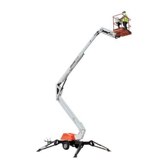
- Page 8 The platform is raised and lowered by the elevating assembly. The hydraulic pump driven by the engine, powers the 3 - stage lift cylinders. CHASSIS The chassis is a structural frame that supports all the components of the TL49J work plat- form. PURPOSE OF EQUIPMENT The objective of the work platform is to provide a quickly deployable, variable height work platform to elevate personnel and materials to overhead work areas.
- Page 9 OPERATION AND SPECIFICATION TL49J Page 2 - 1 Courtesy of Crane.Market...
- Page 10 WARNING All personnel shall carefully read, understand and follow all safety rules and operating instructions before operating or performing maintenance on any SNORKEL aerial work platform. E L E C T R O C U T I O N TIP OVER HAZARD COLLISION HAZARD...
- Page 11 Harness attachment points are provided in the platform and the manufacturer recommends the usage of a fall restraint harness, especially where required by national safety regulations. All harness attachment points on SNORKEL vehicles have been tested with a force of 3,650 lbs (16.3 KN) per person.
- Page 12 5. Never use a machine that is damaged or not functioning properly. Verify that all labels are in place and legible before using. Page 2 - 4 TL49J Courtesy of Crane.Market...
- Page 13 FAX: +44 (0) 845 1557 756 Erkend vertegenwoordiger Auktoriserad representant Autorisert representant Represenentant Valtuutettu edustaja Signed for Snorkel Description ........Aerial Work Platform Bezeichnung ........Arbeitsbühne Description ........Plate-forme elevatrice de personnel Descripcion ........Platforma aerea de trabajo con motor Jan-16 Descrizione ........Piattaforma di sollevamento motorizzata Beschrijving ........Mechanisch aangedreven werkplatform...
-
Page 14: Table Of Contents
2-19 UPPER CONTROLS 2-20 PLATFORM 2-21 SIDE TRAY COVERS 2-21 EMERGENCY PROCEDURE 2-22 EMERGENCY SLEW 2-22 EMERGENCY LOWERING VALVES 2-22 EMERGENCY LOWERING HANDPUMPS 2-23 EMERGENCY LOWERING SWITCH 2-23 PLATFORM OVERLOAD SWITCH 2-24 Page 2 - 6 TL49J Courtesy of Crane.Market... -
Page 15: Introduction
INTRODUCTION INTRODUCTION This manual covers the operation of the TL49J work platform. This manual must be stored on the machine at all times. GENERAL DESCRIPTION Boom structure Upper Controls Lower/Ground Emergency Platform Controls Lowering Valve Toeboards Outriggers Identification Wheels Number Plate... -
Page 16: Special Limitations
Slight structural damage occurs (chimney pots and slates removed) Table 2-1: Beaufort scale Never operate the machine when wind speed exceeds 12.5 m/s (28 mph) as indicated on the Beaufort scale 6. Page 2 - 8 TL49J Courtesy of Crane.Market... -
Page 17: Platform Overload Alarm
To re-start the machine functions, the excess load must be first removed to stop the alarm from sounding. D A N G E R Never operate the machine with a platform load greater than the rated capacity. TL49J Page 2 - 9 Courtesy of Crane.Market... -
Page 18: Controls/Pre-Operation
Raise Lower Raise Retract Tele Raise Top Anti-clockwise Boom Dropnose Boom Boom Lower Lower Top Slew Lower Lower Extend Tele Clockwise Dropnose Boom Boom Boom Figure 2-3: Chassis controls and indicator locations Page 2 - 10 TL49J Courtesy of Crane.Market... -
Page 19: Pre-Operation Safety
The battery tray is located on the left side of the aerial platform. W A R N I N G DO NOT not smoke or permit open flames or sparks when checking the batteries. TL49J Page 2 - 11 Courtesy of Crane.Market... -
Page 20: Battery Terminals
1. Visually check that the platform overload switch is free from damage. 2. Check all limit switch arms are fee from damage and move easily. 3. Check to make sure the platform does not extend when outriggers are raised. Page 2 - 12 TL49J Courtesy of Crane.Market... -
Page 21: Battery Charger
2. Check the wiring in areas where a change in routing direction may cause them to become pinched. 3. Make sure the cables and wires are properly routed to avoid sharp edges, pinching, and scuffing. TL49J Page 2 - 13... -
Page 22: Hydraulic System
Refer to specifications on page 2-32 for the proper type and grade of hydraulic fluid to use. The need to regularly add fluid indicates a leak that should be corrected. 3. Replace the cap making sure it is secured in place. Page 2 - 14 TL49J Courtesy of Crane.Market... -
Page 23: Hoses, Tubes And Fittings
2. At the lower controls, twist and pull the emergency stop switch outwards to the ON position. 3. Turn the control select switch to lower controls (turn to the right). Figure 2-9 – Battery Disconnect TL49J Page 2 - 15 Courtesy of Crane.Market... -
Page 24: Emergency Slew
With the outriggers down, under load, the machine level with the wheels clear of the ground, turn the control select switch to the lower controls (turn switch to the right). • Insert the hand pump lever into the pump shaft. Page 2 - 16 TL49J Courtesy of Crane.Market... -
Page 25: Structures
Inspect the platform and upper controls only if all functions operated properly from the lower controls. GUARDRAIL SYSTEM The guardrail system includes (refer to Figure 2-11): A top rail A mid rail Drop bar Toeboards around the sides of the platform TL49J Page 2 - 17 Courtesy of Crane.Market... -
Page 26: Emergency Lowering Switch
1. Push the emergency stop button inward to turn off electrical power. 2. Test the upper control functions to make sure they do not operate with the emergency stop in this position. Page 2 - 18 TL49J Courtesy of Crane.Market... -
Page 27: Operation
Platform Raise/Lower Button Lower Controls Outrigger Raise/Lower Levers Emergency Platform Raise/Lower Levers Lowering Switch C o n t r o l S e l e c t / Ground Opera- tion Switch TL49J Page 2 - 19 Courtesy of Crane.Market... -
Page 28: Upper Controls
6. Hold down on the platform raise lower button. 7. Still holding the platform raise/lower button down, use the platform raise/lower levers to raise/ lower the platform. 8. Release either the button or levers to stop movement. Page 2 - 20 TL49J Courtesy of Crane.Market... - Page 29 To open the tray, pull upward on the latch (step 1) and open the cover (step 2)(refer to Figure 15). The latched tray cover must be opened first to enable access to the battery tray. When closing the tray cover, reverse the process to lock it in place. TL49J Page 2 - 21 Courtesy of Crane.Market...
- Page 30 • Press on the lowering valve button to initiate lowering and facilitate access to the top ram valve. Note Each emergency ram valve will automatically close when the button is released. Figure 2-17 – Emergency Valve Location Page 2 - 22 TL49J Courtesy of Crane.Market...
- Page 31 D A N G E R If the emergency lower is used due to a machine defect, do not use the machine. Contact your local Snorkel representative. W A R N I N G If the emergency lower is used, the top and bottom booms must be fully extended then fully lowered before work can continue.
- Page 32 In a situation where the excess load cannot be removed immediately then the platform overload switch (refer to Figure 2-13) can be used to move the platform to a safe position so that the excess load can be removed safely. Page 2 - 24 TL49J Courtesy of Crane.Market...
-
Page 33: Transportation
The empty vehicle weight is listed in Chapter 2 and is stamped on the serial number placard. The user assumes all responsibility for: Choosing the proper method of transportation. Choosing the proper selection and use of transportation and tie-down devices. TL49J Page 2 - 25 Courtesy of Crane.Market... -
Page 34: Transportation
Know the weight of the aerial platform and the capacity of the lifting devices before hoisting. Lifting devices include the hoist or crane, chains, straps, cables, hooks, sheaves, shackles, slings, and other hardware used to support the machine. Page 2 - 26 TL49J Courtesy of Crane.Market... -
Page 35: Towing
4. Ensure that all outriggers are fully raised. 5. Use the jockey wheel to raise or lower the tow bar coupling to position the machine above the 50 mm ball hitch on the towing vehicle (refer to Figure 2-23). TL49J Page 2 - 27 Courtesy of Crane.Market... -
Page 36: Friction Drive Assist Package
3. Turn the Control select/ground operation switch to lower controls. 4. Disengage the handbrake and ensure that the locking pin stopping the tow bar coupling from rotation is removed to enable the jockey wheel to be lowered. Page 2 - 28 TL49J Courtesy of Crane.Market... - Page 37 Push the right lever only forwards or backwards to turn the machine to the left. Figure 2-26 – Hydraulic Levers 6. Ensure the hand brake is engaged when the machine is in position TL49J Page 2 - 29 Courtesy of Crane.Market...
-
Page 38: Inspection And Maintenance
The daily preventative maintenance checklist has been designed for machine service and mainte- nance. Photocopy the checklist page and use the checklist when inspecting the machine. Page 2 - 30 TL49J Courtesy of Crane.Market... -
Page 39: Daily Preventative Maintenance Schedule
Check the structure and welds for dam- age, deformation, corrosion and cracks Check condition of deck (no damage, deformation, corrosion or cracks Check entry gate closure functions correcly Table 2-2: Daily preventative maintenance checklist TL49J Page 2 - 31 Courtesy of Crane.Market... -
Page 40: Specifications
SPECIFICATIONS ITEM TL49J Operating Dimensions Maximum platform height 48' (14.7 m) Guardrail height 3.61' (1.10 m) Maximum working height 54.8' (16.7 m) Platform length 47" (1.2 m) Platform width 31.5" (0.8 m) Platform height 6.3" (0.16 m) Maximum outreach (from center of rotation) 27' (8.23 m) - Page 41 Maximum wind speed 28 mph (12.5 m/s) Table 2-3: TL49J Specification NOTE: Specifications are subject to change without notice. Hot weather or heavy use may affect performance. Refer to the service manual for complete parts and service information. This ma- chine meets or exceeds all applicable OSHA and ANSI A92.6 - 1999.
- Page 42 End of Life Waste Advice Chart : Your waste can't be recycled as scrap metal. Is the waste: A solid metal ? Is the metal: Aluminum, Copper, Iron, should be RECYCLED according to the universal Lead, Steel, or Zinc? Your waste is a HAZARDOUS WASTE Follow your RECYCLED...
- Page 43 OUTRIGGER CONTROL VALVE 3-14 RESTRICTORS 3-14 SLEW MOTOR 3-14 GENERAL TESTS OF LOAD HOLDING VALVES 3-15 SLEWING PLATFORM RAM 3-15 BLEEDING 3-15 HYDRAULIC PUMP 3-15 ENGINE SETTINGS 3-16 ELECTRICAL START/STOP 3-17 LEVEL GAUGE 3-17 TL49J Page 3 - 1 Courtesy of Crane.Market...
-
Page 44: Construction Standard
This manual focuses on the maintenance and repair of the machine. Please read the operators manual available from Snorkel or from your local distributor prior to operating the machine. All operator’s and service personnel should have read and understood the operator’s manual and received full training in the safe use of the machine before attempting to use it or carrying out repairs. - Page 45 In the event of a failure, the machine can be manually slewed by moving the slew platform clock- wise or anticlockwise by inserting the slew lever and rotating the gearbox by moving upwards and downwards. TL49J Page 3 - 3 Courtesy of Crane.Market...
- Page 46 This will provide the operator under normal circumstances, a full days work. The charger can also be connected to the mains supply if re-charging is needed. The machine cannot be run directly from Page 3 - 4 TL49J Courtesy of Crane.Market...
-
Page 47: Maintenance Schedule
Snorkel or its local representative. Note If this manual was not issued with the machine, check for updates and revisions from Snorkel or its local representative. Failure to maintain the machine as specified will invalidate the warranty. - Page 48 Check that the outriggers can- not be raised with the top or bottom boom elevated. Hydraulic safety system Check that all emergency low- ering valves work. Check emergency slew Check emergency hand pump. Page 3 - 6 TL49J Courtesy of Crane.Market...
- Page 49 Check for wear - Perform checks after every 3000 miles Table 3-5: Monthly checklist. 6 MONTHLY CHECKS ACTION NOTES Change oil and filter. Thorough Inspection Contact Snorkel or its local representative. Table 3-6: 6 Monthly checklist. TL49J Page 3 - 7 Courtesy of Crane.Market...
-
Page 50: Maintenance Procedure
8. De-grease and replace the large “O” ring and apply a small amount of silicone around the circumference of the de-greased tank neck. 9. Place the tank back on and secure with the 4 bolts removed earlier. Page 3 - 8 TL49J Courtesy of Crane.Market... -
Page 51: Sol 1
190 bar. This setting is put in place to ensure only the safe working load (SWL) is lifted. The centre position is closed to prevent oil back feeding into the tank when operating the platform controls. TL49J Page 3 - 9 Courtesy of Crane.Market... -
Page 52: Platform Controls
The TL49J can be fitted with a variety of power options. The battery powered machine has only one solenoid valve fitted (SOL 1). Both the engine and the mains powered version have a separate dump valve fitted (SOL 2). -
Page 53: Ram Not Holding Under
Replace the piston seals. Figure 3-7: Dropnose cylinder with welded on block containing 2 adjustable O/C valves. TL49J Page 3 - 11 Courtesy of Crane.Market... -
Page 54: Outrigger Ram
In a situation where the ground controls function well but the operation of the boom from the platform controls does not work, then the valve responsible for making the booms lift/lower is the faulty valve. Page 3 - 12 TL49J Courtesy of Crane.Market... -
Page 55: Ground Control Valve
Also look for contamination in the valve or valve cavity. To check that power is reaching the coil, hold a Figure 3-11: Diverter valve schematic. screw driver against the end of the coil. When the TL49J Page 3 - 13 Courtesy of Crane.Market... -
Page 56: Outrigger Control Valve
RESTRICTORS All valve blocks have restrictors fitted at different locations. The current versions (2002) of the TL49J uses a hose adapter with a drilled hole. Other types which have been in use (and currently are on other machines) are a simple copper washer with a sized hole. The copper washer is squashed between the hose fitting and the adapter screwed into the valve block. -
Page 57: Slew Motor
• Remove the bell housing to check that each coupling half is secured on the shaft. Then re- move the pump and check the internal gears. TL49J Page 3 - 15 Courtesy of Crane.Market... -
Page 58: Engine Settings
Use fuel cut-off when moving the machine over long distances. Electrical Throttle Dump Valve Choke Pump Relief valve Fuel Cut-off Figure 3-17: Engine settings. Battery Earth Terminal Engine Oil SAE 10-40 Page 3 - 16 TL49J Courtesy of Crane.Market... -
Page 59: Service And Repair
The level gauge used for setting up the machine is located next to the outrigger control valve block. If the level is damaged or has been removed, do not use the machine until a new level has been fitted. Level Gauge Figure 3-19: Level gauge location. TL49J Page 3 - 17 Courtesy of Crane.Market... -
Page 60: Physical Damage
Note If in doubt, replace or ask Snorkel or its local representative for advice. NUTS & BOLTS Replace any missing bolts immediately. The main pivot shafts and pivot pins are secured with one or two locking pegs. -
Page 61: Locking Peg
When towing, insert the pin and lock in place with the “R” clip provided. During inspection, look for indication of the machine being moved without the pin. Signs of damage include dents in the top boom and crack lines below the vertical boom. Contact Snorkel or its local representative for repairs. R Clips Fixing Clips Figure 3-21: Level gauge location. -
Page 62: Tie Down Lugs
• 50% solid green LED light, 75% solid green LED light and a 100% solid green LED light – indicates that the charge cycle is complete. The fuse used is a 24 V (15 A) fuse. Page 3 - 20 TL49J Courtesy of Crane.Market... - Page 63 Keep the top of the batteries clean and free from dirt. It is very easy for the battery to be contaminated when topping up with distilled water. Regular topping up with distilled water will be required from time to time. TL49J Page 3 - 21 Courtesy of Crane.Market...
-
Page 64: Emergency Stop
• Check that the audible alarm is working. It should sound when the outriggers are unstable. Figure 3-24: Boom limit switch. Figure 3-25: Diverter valve. Page 3 - 22 TL49J Courtesy of Crane.Market... -
Page 65: Wheels
(55 PSI) and not what may be indicated on the tyre. Refer to the tyre pressure sticker fitted on the top of the mudguard. Tyre size is 205/75R16. Note For full service and maintenance information on the running gear, contact Snorkel to request a copy of the running gear OEM service handbook. BRAKES Check Bowden cable for damage - Replace if inner steel core is visible. -
Page 66: Axle
M10 ball nut on the brake rod until there is no further play on the pivot head against the draw bar (the draw bar must be fully extended). The compensating bracket must be square on the brake rod. The current type of Bowden cables are Page 3 - 24 TL49J Courtesy of Crane.Market... -
Page 67: Wheel Bearings
When purchasing a brake drum, the bearings are normally included fitted to the brake drum. If replac- ing the bearings only, contact Snorkel or its local representative for further information. Always use a new flanged nut and torque to between 280 - 300 Nm when re-fitting the drum. -
Page 68: Tl49 Rear Lights
FUNCTION YELLOW L.H. INDICATOR BROWN R.H.TAIL BLUE REAR FOG LAMP(S) STOP LIGHTS WHITE EARTH BLACK L.H. TAIL & NUMBER PLATE GREEN R.H. INDICATOR Figure 3-34: Colour and function table for rear lights. Page 3 - 26 TL49J Courtesy of Crane.Market... -
Page 69: General Grease Points
Additionally, the ring gear and gear box should be greased on a six monthly basis. The grease nipple TL49J Page 3 - 27 Courtesy of Crane.Market... -
Page 70: Slew Stop
This provides almost two turns (lock to lock). From the parking position, this equates to one left turn or one right turn. Page 3 - 28 TL49J Courtesy of Crane.Market... - Page 71 Check hydraulic pressure. Apply plenty of lubrication to ensure that the slew stop ring has not got jammed. Again, if the problem does not disappear contact Snorkel or its local representative for further assistance.
- Page 72 Page 3 - 30 TL49J Courtesy of Crane.Market...
- Page 73 TROUBLESHOOTING CONTENTS FAULT FINDING FAULT FINDING MATRIX TL49J Page 4 - 1 Courtesy of Crane.Market...
- Page 74 If difficulty is experienced in identifying a fault, contact Snorkel for assistance. A list of troubleshoot- ing notes are also listed below to help with solutions to faults identified.
- Page 75 Burnt out mains isolating transformer (Mains Check fuse. powered machines) Check coil on selector valve and dump valve for cracks/signs of water damage. Table 3-3: Fault finding list and possible solutions. TL49J Page 4 - 3 Courtesy of Crane.Market...
- Page 76 Are the Batteries Fully Charged? Charge Batteries & Read Operators Manual Has the Circuit Breaker tripped? If further advice is required, consult Reset the Circuit Breaker Snorkel & Read Operators Manual Technician. Page 4 - 4 TL49J Courtesy of Crane.Market...
- Page 77 Use a shorter Extension lead Snorkel Technician. All extensions must be a minimum of 2.5mm², and no longer than 10m, due to possible voltage drop, which will damage the motor. TL49J Page 4 - 5 Courtesy of Crane.Market...
- Page 78 Are the Batteries Fully Charged? Charge Batteries & Read Operators Manual Has the Circuit Breaker tripped? If further advice is required, consult Reset the Circuit Breaker Snorkel & Read Operators Manual Technician. Page 4 - 6 TL49J Courtesy of Crane.Market...
- Page 79 Are the Hydraulics under pressure? A change of motor tone can be heard. If further advice is Is there enough Oil in the tank? required, consult Snorkel Technician. Top up Oil Level & Read Operators Manual TL49J Page 4 - 7 Courtesy of Crane.Market...
- Page 80 Are the Hydraulics under pressure? A change of motor tone can be heard. Is there enough Oil in the tank? If further advice is required, consult Snorkel Technician. Top up Oil Level & Read Operators Manual Page 4 - 8 TL49J Courtesy of Crane.Market...
- Page 81 Is the Boom Down Switch Made and w orking correctly? Lower the boom s un til the switch is m ade & Read Operators Manual If further advice is required, consult NO CHANGE Snorkel Technician. TL49J Page 4 - 9 Courtesy of Crane.Market...
- Page 82 & Read Operators Manual Is there enough Oil in the tank? NO CHANGE If further advice is required, consult Snorkel Top up Oil Level & Read Operators Technician. Manual Page 4 - 10 TL49J Courtesy of Crane.Market...
- Page 83 TL49 MAINS - GENSET PG ELECTRIC SCHEMATIC - 513354-007 TL49 BATTERY/MAINS HYDRAULICS SCHEMATIC - 515057-000 TL49 DIESEL/PETROL HYDRAULICS SCHEMATIC - 515057-001 5-10 TL49 BI-FUEL HYDRAULICS SCHEMATIC - 515057-002 5-11 TL49 BI-FUEL/FRICTION DRIVE OPTION SCHEMATIC - 515057-002 5-12 TL49J Page 5 - 1 Courtesy of Crane.Market...
-
Page 84: Tl49 Battery Pg Electric Schematic - 513354-001
SCHEMATICS TL49 BATTERY PG ELECTRIC SCHEMATIC - 513354-001 Page 5 - 2 TL49J Courtesy of Crane.Market... -
Page 85: Tl49 Petrol Pg Electric Schematic - 513354-002
SCHEMATICS TL49 PETROL PG ELECTRIC SCHEMATIC - 513354-002 TL49J Page 5 - 3 Courtesy of Crane.Market... -
Page 86: Tl49 Diesel Pg Electric Schematic - 513354-003
SCHEMATICS TL49 DIESEL PG ELECTRIC SCHEMATIC - 513354-003 Page 5 - 4 TL49J Courtesy of Crane.Market... -
Page 87: Tl49 Bi-Petrol Pg Electric Schematic - 513354-004
SCHEMATICS TL49 BI-PETROL PG ELECTRIC SCHEMATIC - 513354-004 TL49J Page 5 - 5 Courtesy of Crane.Market... -
Page 88: Tl49 Bi-Diesel Pg Electric Schematic - 513354-005
SCHEMATICS TL49 BI-DIESEL PG ELECTRIC SCHEMATIC - 513354-005 Page 5 - 6 TL49J Courtesy of Crane.Market... -
Page 89: Tl49 Mains Pg Electric Schematic - 513354-006
SCHEMATICS TL49 MAINS PG ELECTRIC SCHEMATIC - 513354-006 TL49J Page 5 - 7 Courtesy of Crane.Market... -
Page 90: Tl49 Mains-Genset Pg Electric Schematic - 513354-007
SCHEMATICS TL49 MAINS-GENSET PG ELECTRIC SCHEMATIC - 513354-007 Page 5 - 8 TL49J Courtesy of Crane.Market... -
Page 91: Tl49 Battery/Mains Hydraulics Schematic - 515057-000
SCHEMATICS TL49 BATTERY/MAINS HYDRAULICS SCHEMATIC - 515057-000 TL49J Page 5 - 9 Courtesy of Crane.Market... -
Page 92: Tl49 Diesel/Petrol Hydraulics Schematic - 515057-001
SCHEMATICS TL49 DIESEL/PETROL HYDRAULICS SCHEMATIC - 515057-001 Page 5 - 10 TL49J Courtesy of Crane.Market... -
Page 93: Tl49 Bi-Fuel Hydraulics Schematic - 515057-002
SCHEMATICS TL49 BI-FUEL HYDRAULICS SCHEMATIC - 515057-002 TL49J Page 5 - 11 Courtesy of Crane.Market... -
Page 94: Tl49 Bi-Fuel/Friction Drive Option Schematic - 515057-002
SCHEMATICS TL49 BI-FUEL/FRICTION DRIVE OPTION SCHEMATIC - 515057-002 Page 5 - 12 TL49J Courtesy of Crane.Market... - Page 95 ILLUSTRATED PARTS LIST INTRODUCTION This section lists and illustrates the replaceable assemblies and parts of this product as manufac- tured by Snorkel. Each part list contains the component parts for that assembly. CONTENTS LIGHTING BOARD ASSEMBLY BI-FUEL PLATFORM CONTROL PANEL...
-
Page 96: Lighting Board Assembly
Harness, rear light to registration lamp 513838-000 Harness, rear light to side marker lamp 513492-000 Amber marker lamp White reflector 513403-000 512687-000 13 pin plug 512689-000 8 core cable Table 6-2: Marker lamp kit components. Page 6 - 2 TL49J Courtesy of Crane.Market... -
Page 97: Outrigger Assembly
Outrigger 10-5070 Outrigger foot 13-3608 Outrigger ram 22-5179 Outrigger ram cover 15-0886 Ram cover skid pad 12-2054 Banjo bolt SB-030030 Bush SP-016E216 SP-030D171 SP-030D203 SP-030K211 10-2627 Retaining peg Table 6-3: Outrigger components. TL49J Page 6 - 3 Courtesy of Crane.Market... -
Page 98: Chassis Assembly
ILLUSTRATED PARTS LIST CHASSIS ASSEMBLY Figure 6-3: Chassis assembly. Page 6 - 4 TL49J Courtesy of Crane.Market... - Page 99 Knott 300 x 60 std. Brake assembly DPSM 63 90 10 Oil seal 368A/362A Inner Bearing cone/cup LM501349/501310 Outer bearing cone/cup 24929.03 Standard brake shoe 1053 08 Load washer Table 6-5: Brake hub components. TL49J Page 6 - 5 Courtesy of Crane.Market...
-
Page 100: Slew - Bi Fuel Power
ILLUSTRATED PARTS LIST SLEW - BI-FUEL POWER Figure 6-4: Slew (Bi-fuel) assembly. Page 6 - 6 TL49J Courtesy of Crane.Market... - Page 101 Retaining peg - large 035D320 21-0852 22-5577 Splash guard 20-0055 Kubota OC60 diesel engine c/w stop/start kit 20-0044 Honda petrol engine 13-0529 In-line check valve 13-1949 Bell housing 13-1950 Flexible coupling 13-3649 Pump TL49J Page 6 - 7 Courtesy of Crane.Market...
-
Page 102: Slew - Mains Power
ILLUSTRATED PARTS LIST SLEW - MAINS POWER Figure 6-5: Slew (mains) assembly. Page 6 - 8 TL49J Courtesy of Crane.Market... - Page 103 22-5581 Control box cover 13-0888 Base control valve 11-3448 Bolt 10-2672 Retaining peg 24-2880 Retaining peg - Large SP-035D320 21-0852 22-5508 Emergency Battery Holder 09-2087 Dry battery Table 6-7: Slew (mains) components. TL49J Page 6 - 9 Courtesy of Crane.Market...
-
Page 104: Slew - Battery Power
ILLUSTRATED PARTS LIST SLEW - BATTERY POWER Figure 6-6: Slew (battery) assembly. Page 6 - 10 TL49J Courtesy of Crane.Market... - Page 105 Control box cover 13-0888 Base control valve 11-3448 Bolt 10-2672 Retaining peg 24-2880 Retaining peg - large SP-035D320 21-0852 24-4438 Ø 10mm tie bar 24-4439 Battery hold bracket Table 6-8: Slew (battery) components. TL49J Page 6 - 11 Courtesy of Crane.Market...
-
Page 106: Slew - Engine Power
ILLUSTRATED PARTS LIST SLEW - ENGINE POWER Figure 6-7: Slew (engine) assembly. Page 6 - 12 TL49J Courtesy of Crane.Market... - Page 107 13-3549 In-line check valve 13-1949 Bell housing 13-1950 Flexible coupling 13-3649 Pump 13-3650 Outlet elbow 13-3651 Suction elbow 10-5269 Engine mounting bracket 10-5270 Battery/pump cover 09-1010 Battery Table 6-9: Slew (engine) components. TL49J Page 6 - 13 Courtesy of Crane.Market...
-
Page 108: Lower Boom
ILLUSTRATED PARTS LIST LOWER BOOM Figure 6-8: Lower boom assembly. Page 6 - 14 TL49J Courtesy of Crane.Market... - Page 109 21-0852 SP-035D201 21-0850 SP-030D320 SP-035D320 SB-060060 Bush SB-035035 Bush SB-030030 Bush SB-025025 Bush 10-2672 Retaining peg 24-2880 Retaining peg 15-0884 Boom rest pad 15-0883 Boom rest pad Table 6-10: Lower boom components. TL49J Page 6 - 15 Courtesy of Crane.Market...
-
Page 110: Top Boom
ILLUSTRATED PARTS LIST TOP BOOM Figure 6-9: Top boom assembly. Page 6 - 16 TL49J Courtesy of Crane.Market... - Page 111 SP-025D200 SP-040D203 SP-025A120 SP-025D164 10-2672 Retaining peg SB-030030 Bush SB-040040 Bush SB-025025 Bush 09-2121 Cable tray 24-3909 Hose trunking 15-0883 Boom rest pad 15-1009 Drag chain complete Table 6-11: Top boom components. TL49J Page 6 - 17 Courtesy of Crane.Market...
-
Page 112: Dropnose
DROP NOSE Figure 6-10: Drop nose assembly. ITEM PART # DESCRIPTION 10-5078 Drop nose boom 10-5077 Quadrant 13-3602 Drop nose ram SP-025D200 SP-030D216 10-2672 Retaining peg SB-025025 Bush Table 6-12: Drop nose components. Page 6 - 18 TL49J Courtesy of Crane.Market... -
Page 113: Cage Support
Pin - ANSI SP-025D330 SP-016B108 10-2672 Retaining peg SB-025015 Bush SB-025025 Bush SB-016020 Bush 04-0113 Thrust washer 13-2403 Cage rotation ram 23-0031 Spring 11-3442 Bolt (M12 x 170 mm) Table 6-13: Cage support components. TL49J Page 6 - 19 Courtesy of Crane.Market... -
Page 114: Steel Cage
ILLUSTRATED PARTS LIST STEEL CAGE Figure 6-12: Steel cage assembly. Page 6 - 20 TL49J Courtesy of Crane.Market... - Page 115 Platform control panel (Battery) 513321-005 Platform control panel (Engine) 513321-006 Platform control panel (Bi-fuel) 513321-004 Platform control panel (Mains) 508140-000 09-2126 Amber marker lamp 09-1939 Swivel light Table 6-14: Steel cage components. TL49J Page 6 - 21 Courtesy of Crane.Market...
-
Page 116: Grp Basket
Socket (110 V) 09-1392 Socket (230 V) 513321-004 Platform control panel (Battery) 513321-005 Platform control panel (Engine) 513321-006 Platform control panel (Bi-fuel) 513321-004 Platform control panel (Mains) Table 6-15: GRP basket components. Page 6 - 22 TL49J Courtesy of Crane.Market... -
Page 117: Outrigger Ram
PART # DESCRIPTION 13-3608-1 Tube assembly 13-2351 Seal kit 13-1004 Head bush 13-0604 PO Check valve 13-0973 Locknut 13-1007 Piston SS-0400023 Spacer 13-3608-2 Rod assembly Table 6-16: Outrigger ram components - 13-3608. TL49J Page 6 - 23 Courtesy of Crane.Market... -
Page 118: Bottom Ram
Seal kit 13-0968 Head bush 13-0392 Over-centre valve 13-2474/2 Emergency lower valve 09-2090 Solenoid 13-2425/77 Hirschmann connector 13-0973 Locknut 13-0971 Piston SS-0500343 Spacer 13-3607-2 Rod assembly Table 6-17: Bottom ram components - 13-3607. Page 6 - 24 TL49J Courtesy of Crane.Market... -
Page 119: Top Ram
Seal kit 13-0968 Head Bush 13-0392 Over-centre valve 13-2474/2 Emergency lower valve 09-2090 Solenoid 13-2425/77 Hirschmann 13-0973 Locknut 13-0971 Piston SS-0500037 Spacer 13-3606-2 13-3606-3 Bearing Table 6-18: Top ram components - 13-3606. TL49J Page 6 - 25 Courtesy of Crane.Market... -
Page 120: Master Ram
Figure 6-17: Master ram assembly. ITEM PART # DESCRIPTION 13-3604-1 Tube assembly 13-3603-3 Seal kit 13-1061 Head bush 13-0973 Locknut 13-1064 Piston 13-3604-2 Rod assembly Table 6-19: Master ram components - 13-3604. Page 6 - 26 TL49J Courtesy of Crane.Market... -
Page 121: Telescopic Ram
13-3605-1 Tube assembly 13-3605-3 Seal kit 13-3605-4 Head bush 13-0472 Over-centre valve 13-0659 PO check valve 13-3605-5 Piston 13-3605-6 Locknut 13-3605- Spacer 13-3605-2 Rod assembly Table 6-20: Telescopic ram components - 13-3605. TL49J Page 6 - 27 Courtesy of Crane.Market... -
Page 122: Levelling Ram
Figure 6-19: Levelling ram assembly. ITEM PART # DESCRIPTION 13-3603-1 Tube assembly 13-3603-3 Seal kit 13-1061 Head bush 13-2489 Over-centre valve 13-1064 Piston 13-0973 Locknut 13-3603-2 Rod assembly Table 6-21: Levelling ram components - 13-3603. Page 6 - 28 TL49J Courtesy of Crane.Market... -
Page 123: Dropnose Ram
PART # DESCRIPTION 13-3602-1 Tube assembly 13-3603-3 Seal Kit 13-1061 Head bush 13-2489 Over-centre valve 13-1064 Piston 13-0973 Locknut 13-3602-3 Spacer 13-3602-2 Rod assembly Table 6-22: Drop nose ram components - 13-3602. TL49J Page 6 - 29 Courtesy of Crane.Market... -
Page 124: Cage Rotation Ram
Figure 6-21: Cage rotation ram assembly. ITEM PART # DESCRIPTION 13-2403-1 Tube assembly 13-0993 Seal kit 13-0988 Head bush 13-0992 Piston 13-0994 Locknut SS-0200020 Spacer 13-2403-2 Rod assembly Table 6-23: Drop nose ram components - 13-2403. Page 6 - 30 TL49J Courtesy of Crane.Market... -
Page 125: Trailer Electric Kit Parts
ILLUSTRATED PARTS LIST TRAILER ELECTRIC KIT PARTS STANDARD LOWER CONTROL PANEL Figure 6-22: Standard lower control panel assembly - 513348-000. TL49J Page 6 - 31 Courtesy of Crane.Market... - Page 126 Spacer 512817-000 15 way panel plug 513319-000 Lower control box - trailers 510152-000 Cable gland 510153-000 Cable gland 09-2378 Switch cable 09-2379 Switch cable 09-2326 Relay 24 V DC 513350-000 5-Core cable Page 6 - 32 TL49J Courtesy of Crane.Market...
-
Page 127: Standard Platform Control Panel
ILLUSTRATED PARTS LIST STANDARD PLATFORM CONTROL PANEL Figure 6-23: Standard platform control panel assembly - 513321-000. TL49J Page 6 - 33 Courtesy of Crane.Market... - Page 128 Cable mounting plate 512651-010 Socket HD capscrew - M3 x 10 510561-003 Flat washer - M3 510569-003 M3 nylock nut - stainless steel Table 6-25: Standard Platform control panel components - 513321-000. Page 6 - 34 TL49J Courtesy of Crane.Market...
-
Page 129: Battery/Mains Platform Control Panel
PART # DESCRIPTION 513321-000 Platform control panel (standard) 512449-000 Keyswitch 2 position stayput 513328-004 TL49 UCP overlay bat/mains 513307-000 Switch 3-way spring to center Table 6-26: Battery/Mains Platform control panel components - 513321-004. TL49J Page 6 - 35 Courtesy of Crane.Market... -
Page 130: Engine Platform Control Panel
Platform control panel (standard) 512449-000 Keyswitch 2 position stayput 513317-000 Green push button 513328-005 TL49 UCP overlay engine 513307-000 Switch 3-way spring to center Table 6-27: Engine Platform control panel components - 513321-005. Page 6 - 36 TL49J Courtesy of Crane.Market... -
Page 131: Bi-Fuel Platform Control Panel
Platform control panel (standard) 512543-000 Keyswitch 3 position stayput 513317-000 Green push button 513328-006 TL49 UCP overlay bi-fuel 513307-000 Switch 3-way spring to center Table 6-28: Bi-fuel Platform control panel components - 513321-006. TL49J Page 6 - 37 Courtesy of Crane.Market... -
Page 132: Mains Motor Starter
ILLUSTRATED PARTS LIST MAINS MOTOR STARTER Figure 6-27: Mains motor starter assembly - 513999-000. Page 6 - 38 TL49J Courtesy of Crane.Market... - Page 133 0.5 m 514009-000 Cable 2.5 mm CSA tri-rated blue 0.5 m 514010-000 Cable 2.5 mm CSA tri rated green/yellow 0.5 m 513067-000 Grey bootlace ferrule Table 6-29: Mains motor starter components - 513999-000. TL49J Page 6 - 39 Courtesy of Crane.Market...
-
Page 134: External Components
Table 6-32: External components - All mains variants. CABLE ASSEMBLIES PART # DESCRIPTION 513323-000 Platform Cable TL49 Table 6-33: Platform cable assembly. PART # DESCRIPTION 513325-000 Battery cable set TL49 Table 6-34: Battery cable assembly. Page 6 - 40 TL49J Courtesy of Crane.Market... -
Page 135: Basic Fittings Kit
3/8" BSP male x 1/4" BSP male straight adaptor 12-1502 3/8" Dowty washer 12-1879 1/4" BSP female x 1/4" BSP female compact 90° elbow Table 6-35: TL49J basic fittings kit - All specifications. TL49J Page 6 - 41 Courtesy of Crane.Market... -
Page 136: End Fittings Kit
T straight straight Pump to manifold P 3/8 702 9/16 JIC female 9/16 JIC female straight 90° Tank manifold to 3/8 702 9/16 JIC female 9/16 JIC female 1000 filter straight straight Page 6 - 42 TL49J Courtesy of Crane.Market... - Page 137 1/2 BSP female 1/2 BSP female 1940 tank suction port straight 90° Pressure relief V/V 1/4 R7 9/16 JIC female 9/16 JIC female 1060 to tank 90° straight Table 6-36: TL49J end fittings kit. TL49J Page 6 - 43 Courtesy of Crane.Market...
-
Page 138: Tl49 Friction Drive Kit
3/8 1SN 9/16 JIC F STR x 9/16 JIC F 90 3275 1/4 1SN 9/16 JIC F STR x 9/16 JIC F STR 910 1/4 1SN 9/16 JIC F STR x 9/16 JIC F STR 1220 Table 6-37: TL49J friction drive kit - 13-3670. Page 6 - 44 TL49J... -
Page 139: Tl49 Decal Locations
ILLUSTRATED PARTS LIST TL49 DECAL LOCATIONS 508521-000 508508-000 508507-000 508507-000 508508-000 18-0578 508523-000 508525-001 18-0483 508506-000 508508-000 508507-000 508507-000 510280-000 508508-000 508522-000 510280-000 508523-000 18-0071 508525-001 508519-000 Table 6-27: TL49J decal locations. TL49J Page 6 - 45 Courtesy of Crane.Market... - Page 140 ILLUSTRATED PARTS LIST 508523-000 508513-000 510280-000 18-0483 508525-001 18-0578 508507-000 Page 6 - 46 TL49J Courtesy of Crane.Market...
- Page 141 ILLUSTRATED PARTS LIST 508522-000 18-0071 508506-000 508508-000 508521-000 508519-000 TL49J Page 6 - 47 Courtesy of Crane.Market...
- Page 142 Courtesy of Crane.Market...
- Page 143 Local Distributor / Lokaler Vertiebshändler / Distributeur local El Distribuidor local / ll Distributore locale EUROPE, MIDDLE EAST AFRICA & ASIA PHONE: +44 (0) 845 1550 057 FAX: +44 (0) 845 1557 756 NORTH & SOUTH AMERICA PHONE: +1 785 989 3000 TOLL FREE: +1 800 225 0317 FAX: +1 785 989 3070 AUSTRALIA...
Need help?
Do you have a question about the TL49J and is the answer not in the manual?
Questions and answers
warning light stays on even though green lights are all on for outriggers and machine operates