Table of Contents
Advertisement
HP-5079-2
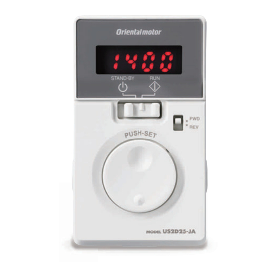
AC Speed Controller
US2
Series
OPERATING MANUAL
Thank you for purchasing an Oriental Motor product.
This Operating Manual describes product handling procedures and safety precautions.
• • Please read it thoroughly to ensure safe operation.
• • Always keep the manual where it is readily available.
Advertisement
Table of Contents

Related Manuals for Oriental motor US2 Series


Summary of Contents for Oriental motor US2 Series
- Page 1 AC Speed Controller Series OPERATING MANUAL Thank you for purchasing an Oriental Motor product. This Operating Manual describes product handling procedures and safety precautions. • • Please read it thoroughly to ensure safe operation. • • Always keep the manual where it is readily available.
-
Page 2: Table Of Contents
Table of contents Introduction ............3 Convenient functions ........15 Before using the product ........3 Functions list ............15 Description of operating manual ...... 3 Panel displays and setting items ......16 Safety precautions ..........4 Data locking for the set data ......17 Display after setting the speed reduction Preparation ............ -
Page 3: Introduction
The product described in this manual has been designed and manufactured to be incorporated in general industrial equipment. Do not use for any other purpose. Oriental Motor Co., Ltd. is not responsible for any damage caused through failure to observe this warning. -
Page 4: Safety Precautions
Safety precautions 2 Safety precautions The precautions described below are intended to prevent danger or injury to the user and other personnel through safe, correct use of the product. Use the product only after carefully reading and fully understanding these instructions. WARNING Handling the product without observing the instructions that accompany a "Warning"... -
Page 5: Preparation
50 C (Locked Rotor Current 1.1A) Cont.(S1) Ins.Class B(S1) IP20 MSIP-REM- 2017/10 SY5 123456 Manufacturing OMC-XXX ORIENTAL MOTOR CO.,LTD. date TOKYO 110-8536 JAPAN 2017/10 ORIENTAL MOTOR CO.,LTD. MADE IN XXXXX Serial number TOKYO 110-8536 JAPAN MADE IN XXXXX UX9 1234567... -
Page 6: Products Possible To Combine
Preparation 3.4 Products possible to combine Be sure to match the output power and power supply voltage of the motor with those of the speed controller. Add -N to the end of the model name 4 when the power supply cable is not supplied. The box ( o ) in the model name indicates the number representing the gear ratio. - Page 7 Preparation „ Right-angle gearhead Hollow hypoid gear JH gearhead „ Speed control motor Speed controller Output Component products Power supply voltage Model Model Component products model power model SCM425KJA-4HoB SCM425KJA Single-phase 100 VAC US2D25-JA-CC US2D25-JA CC02AC02P2 Single-phase 200 VAC SCM425KJC-4HoB SCM425KJC US2D25-JC-CC US2D25-JC...
-
Page 8: Names And Functions Of Parts
Preparation 3.5 Names and functions of parts Front side When the front panel is attached Front side When the front panel is removed Mounting hole Protective lm Use after removing (2 locations) the protective lm. Display Protective lm ESC key FUNCTION key Use after removing Operation... -
Page 9: Installation
Installation 4 Installation This chapter explains the installation location and installation methods. 4.1 Installation location The speed controller described in this manual has been designed and manufactured to be incorporated in general industrial equipment. Install it in a well-ventilated location that provides easy access for inspection. The location must also satisfy the following conditions: •... - Page 10 Installation „ Installation method „ Install the speed controller to a flat metal plate offering excellent vibration resistance. Remove the front panel of the speed controller and secure the two mounting holes using screws, washers, and nuts (M4: not supplied). Tighten the screws until no gaps remain between the speed controller and mounting plate. <...
-
Page 11: Connection
Connection 5 Connection This chapter explains how to connect the speed controller and motor, input signals, and power supply, as well as the grounding method. Motor Speed controller Grounding Motor cable Power supply cabke Cable xing part Power supply Grounding The motor cable can be tightened using a supplied cable-tie. -
Page 12: Connecting The Motor And Speed Controller
Connection 5.2 Connecting the motor and speed controller Connect the motor cable connector to the CN2 on the speed controller. Use an accessory connection cable (sold separately) when extending the wiring distance between the motor and speed controller. The connection cable can be connected up to 3 pieces. Flexible connection cables are also available as accessories. Maximum extension distance between the motor and speed controller: 10.5 m (34.4 ft.) [including 0.5 m (1.6 ft.) of the motor cable] •... -
Page 13: Operation
Operation 6 Operation 6.1 Operation procedure After connecting, operate the product as follows. Names of parts AC power ON Display The display is lit Operation switch (rotation speed) Setting dial Front panel Operation switch ⇒ STAND-BY The motor rotates. Rotation speed Rotation speed Factory setting: 90 r/min Decelerate... -
Page 14: To Adjust The Motor Rotation Speed
Operation 6.2 To adjust the motor rotation speed Setting the operation switch to the "RUN" side causes the motor to rotate. Setting the operation switch to the "STAND-BY" side causes the motor to stop. The speed while the motor is rotating can be adjusted with the setting dial. Operation switch Turning the setting dial slowly Setting dial... -
Page 15: Convenient Functions
Convenient functions 7 Convenient functions 7.1 Functions list Various setting can be performed when removing the front panel. Parameter type Display Setting range Factory setting • • To display the rotation Speed reduction ratio 1.00 to 9999 1.00 speed of the gearhead •... -
Page 16: Panel Displays And Setting Items
Convenient functions 7.2 Panel displays and setting items Power ON : Turn the setting dial : Press the setting dial : Press the ESC key : Press the FUNCTION key Rotation speed monitor Rotation speed monitor Data setting The motor rotation speed is displayed. The display of the lowest digit is xed to "... -
Page 17: Data Locking For The Set Data
Convenient functions 7.3 Data locking for the set data The setting can be locked so that the set rotation speed and parameters do not change. The setting of data and parameters cannot be changed using the setting dial while the data is locked. -
Page 18: Soft Start/Soft Stop Function
Convenient functions • „ Display the conveyor transfer speed To display the conveyor transfer speed, set the conveyor speed reduction ratio, which is calculated using the formula below, to the "speed reduction ratio" parameter. Conveyor Gearhead gear ratio Conveyor speed transfer speed Feed rate per motor revolution Pulley diameter [m] ×... -
Page 19: Limiting The Setting Range Of The Rotation Speed
Convenient functions 7.6 Limiting the setting range of the rotation speed The setting range of the rotation speed using the setting dial can be limited by setting the upper limit and lower limit. Speed setting range Factory setting [r/min] (initial value) 1600 [Example] When limiting the speed range... -
Page 20: Alarms
• • If the product does not operate properly after the power is cycled, the internal circuit may be damaged. Note Contact your nearest Oriental Motor sales office. • • Continuing the operation without removing the cause of the alarm may cause damage to equipment. -
Page 21: Troubleshooting
When the motor cannot be operated correctly, refer to the contents provided in this chapter and take appropriate action. If the problem persists, contact your nearest Oriental Motor sales office. Certain items must be checked with the power on. Perform inspections carefully not to touch the live part Note such as connection part of the motor and speed controller. -
Page 22: Maintenance And Inspection
It is recommended that periodic inspections for the items listed below are conducted after each operation of the motor. If an abnormal condition is noted, discontinue any use and contact your nearest Oriental Motor sales office. • • Conduct the insulation resistance measurement or dielectric strength test separately on the motor and the Note speed controller. -
Page 23: Accessories (Sold Separately)
Accessories (sold separately) 11 Accessories (sold separately) „ Connection cable „ These cables are used to extend the wiring distance between the speed controller and motor. The connection cable can be connected up to 3 pieces. Flexible connection cables are also available. Maximum extension distance between the motor and speed controller: 10.5 m (34.4 ft.) [including 0.5 m (1.6 ft.) of the motor cable] Up to 10 m (32.8 ft.) can be extended... -
Page 24: Regulations And Standards
Regulations and standards 12 Regulations and standards 12.1 UL Standards, CSA Standards This product is recognized by UL under the UL and CSA Standards. Applicable standards Certification body/Standards file number UL 508 UL/UL File No.E91291 CSA C22.2 No.14 12.2 EU Directives „... -
Page 25: Emc Directive
• • Use an accessory connection cable (sold separately) when extending the wiring distance between the motor and speed controller. The EMC measures are conducted using the Oriental Motor connection cable. −25−... - Page 26 Regulations and standards „ Example of installation and wiring „ Motor Speed controller Input signal cable [2 m (6.6 ft.) or less] Motor cable connection cable Maximum extension distance: Grounding 10.5 m (34.4 ft.) [including 0.5 m (1.6 ft.) of the motor cable] AC power supply cable Surge...
-
Page 27: Specifications
Specifications 13 Specifications 13.1 Specifications Check on the Oriental Motor Website for the product specifications. 13.2 General specifications Ambient 0 to +50 °C [+32 to +122 °F] (non-freezing) temperature Ambient 85% or less (non-condensing) humidity Altitude Up to 1000 m (3300 ft.) above sea level Surrounding No corrosive gas, dust, water or oil. - Page 28 If a new copy is required to replace an original manual that has been damaged or lost, please contact your nearest Oriental Motor branch or sales office. • • Oriental Motor shall not be liable whatsoever for any problems relating to industrial property rights arising from use of any information, circuit, equipment or device provided or referenced in this manual.
Need help?
Do you have a question about the US2 Series and is the answer not in the manual?
Questions and answers