Table of Contents
Advertisement
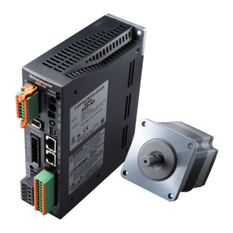
AZ Series/
Motorized Actuator
equipped with AZ Series
EtherCAT Drive Profile Compatible
USER MANUAL
z AC power input type
z DC power input type
Thank you for purchasing an Oriental Motor product.
This Manual describes product handling procedures and safety precautions.
• Please read it thoroughly to ensure safe operation.
• Always keep the manual where it is readily available.
HM-60375
Introduction
AC power input type
DC power input type
EtherCAT communication
Object list
Troubleshooting
Test operation using
pulses
Reference materials
Advertisement
Table of Contents


Need help?
Do you have a question about the Astep AZ Series and is the answer not in the manual?
Questions and answers