Table of Contents
Advertisement
Quick Links
Stored Program Controller
EMP400 Series
OPERATING MANUAL
Thank you for purchasing an Oriental Motor product.
This Operating Manual describes product handling procedures and safety precautions.
Please read it thoroughly to ensure safe operation.
•
Always keep the manual where it is readily available.
•
HP-19036-3
Advertisement
Table of Contents

Related Manuals for Oriental motor EMP400 Series


Summary of Contents for Oriental motor EMP400 Series
- Page 1 HP-19036-3 Stored Program Controller EMP400 Series OPERATING MANUAL Thank you for purchasing an Oriental Motor product. This Operating Manual describes product handling procedures and safety precautions. Please read it thoroughly to ensure safe operation. • Always keep the manual where it is readily available.
-
Page 2: Table Of Contents
How to identify the product model ...9 8 Executing the sequence program..47 Names and functions of parts....10 How to execute a sequence program ... 47 Specifications of EMP400 Series ..10 Program execution via the 5 Installation ........11 host controller ........48 Location for installation ......11... - Page 3 MHOME ............. 73 10.4 Edit mode ..........92 9.5.20. MU .............. 75 10.5 Teaching mode ........93 9.5.21. OFS ............. 76 Operation in teaching mode......94 9.5.22. 10.5.1. OUT ............76 Operation in HOME mode......95 9.5.23. 10.5.2. PULSE ............77 Operation in step execution mode....96 9.5.24.
-
Page 4: Introduction
Oriental Motor shall not be liable for damage to on less of data resulting from the use of this product. Duplicate copies of critically important data should be stored in a separate medium in case a mishap should occur. - Page 5 1 Introduction System configuration A sample system configuration using the EMP400 Series is provided below. Data setter OP300 (sold separately) ∗ The unit cannot be used to write a sequence program. Communication cable FC04W5 (sold separately) Host controller Driver Motor or Linear &...
-
Page 6: Safety Precautions
2 Safety precautions 2 Safety precautions The precautions described below are intended to prevent danger or injury to the user and other personnel through safe, correct use of the product. Use the product only after carefully reading and fully understanding these instructions. Handling the product without observing the instructions that accompany a Warning “Warning”... - Page 7 2 Safety precautions Caution General • Do not use the controller beyond their specifications, or injury or damage to equipment may result. • Keep your fingers and objects out of the openings in the controller, or fire may result. Installation •...
-
Page 8: Precautions For Use
3 Precautions for use 3 Precautions for use This section covers limitations and requirements the user should consider when using the product. Power capacity For the controller, use a DC power supply capable of supplying 24 VDC ±5% at 0.45 A or greater, with reinforced insulation provided on the primary and secondary sides. -
Page 9: Preparation
(26 pins) Case 54331-0261 10326-52A0-008 4.2 How to identify the product model EMP40 1 - 1 Connector 1: Without connectors 2: With connectors (Soldering type) Axis number 1: 1 axis 2: 2 axes Name of the series EMP400 Series -9-... -
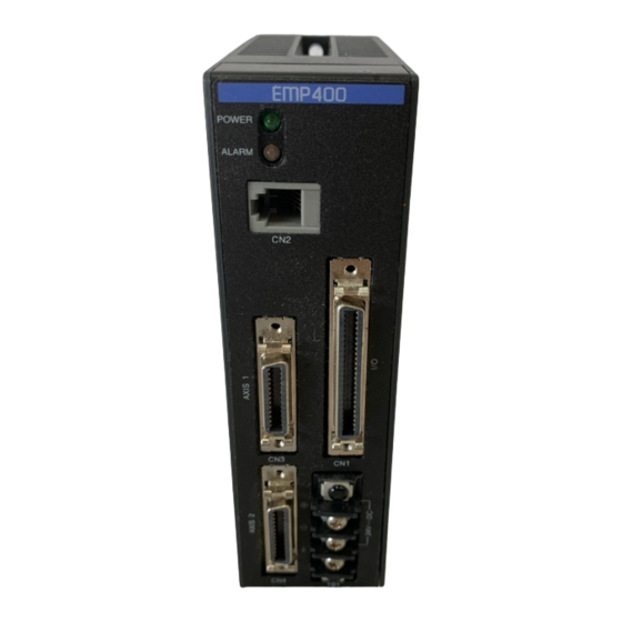
Page 10: Names And Functions Of Parts
Terminal block (TB1) axis I/O and sensor. ∗ Used to connect the 24 VDC EMP402 only power supply and frame ground. 4.4 Specifications of EMP400 Series Control axis number 1 or 2 Number of sequence 32 (sequence programs 0 through 31) programs The sequence program 99 is a CONFIG program. -
Page 11: Installation
5 Installation 5 Installation This section covers the conditions and method for controller installation. 5.1 Location for installation This controller is designed and manufactured for installation in equipment. Install them in a well-ventilated location that provides easy access for inspection. The location must also satisfy the following conditions: •... -
Page 12: Installation Method
5 Installation 5.3 Installation method Mount the controller on a DIN rail. In case the DIN rail produces significant vibrations, mount the controller on an appropriate metal plate. Mounting the controller on a DIN rail Use a DIN rail of 35 mm (1.38 in.) in width. Use the end plates to secure the controller mounted on the DIN rail. -
Page 13: Connection
6 Connection This section covers the methods for connecting the power, driver, host controller and other units to the EMP400 Series controller, as well as the grounding method, I/O circuits and a connection example. 6.1 Assembling the connector Solder-type connectors are supplied with the EMP401-2 and EMP402-2 Series controllers. -
Page 14: Connecting The Power Supply
6 Connection 6.2 Connecting the power supply The controller’s power supply is connected to the TB1 terminals. In addition to the power supply terminals, TB1 has a frame ground (FG) terminal to prevent malfunctions caused by external noise. The power supply provides a voltage of 24 VDC ±5% with current consumption of 0.45 A or less. The current consumption level includes the current supplied to the operational unit. -
Page 15: Connecting The Host Controller (Cn1)
6 Connection 6.3 Connecting the host controller (CN1) Connection method 6.3.1. Use the I/O connector (50 pins) for connection with the host controller. Plug the I/O connector into CN1 and tighten the screw. Screws CN1 (I/O) signal table Pin No. Signal Description Pin No. -
Page 16: Internal Input Circuit
6 Connection Internal input circuit 6.3.2. Memo The signal state represents the “ON: Carrying current” or “OFF: Not carrying current” state of the internal photocoupler rather than the voltage level of the signal. +COM 820 Ω E-STOP, START S-STOP, IN1 to IN8 5.4 kΩ... -
Page 17: Internal Output Circuit
6 Connection Internal output circuit 6.3.3. Memo The signal state indicates the “ON: current supplied” or “OFF: current not supplied” status of the photocoupler inside a host controller rather than the voltage level of the signal. +COM ALM, MOVE, READY OUT1 to OUT6, END 25 mA or less... -
Page 18: Connection Example To A Host Controller
6 Connection Connection example to a host controller 6.3.4. EMP400 Series Host controller etc. ∗ +24 VDC +COM 7, 16, 32 E-STOP 5.4 kΩ 5.4 kΩ START Control input S-STOP 5.4 kΩ 5.4 kΩ Sequence program selection 5.4 kΩ 5.4 kΩ... -
Page 19: Connecting The Driver
6 Connection ∗ only 6.4 Connecting the driver (CN3 · CN4 EMP402 Connection method 6.4.1. Use the AXIS connector (26 pins) for connection with the driver. Plug the AXIS connectors for the first- and second-axis drivers into CN3 and CN4, respectively, and tighten them with screws. Screws CN3·CN4 signal table Pin No. -
Page 20: Internal Input Circuit
6 Connection Internal input circuit 6.4.2. Memo The signal state indicates the “ON: current supplied” or “OFF: current not supplied” state of the internal photocoupler rather than the voltage level of the signal. +12 V 1 kΩ END, TIM., ALM +LS, -LS 2.7 kΩ... -
Page 21: Internal Output Circuit
6 Connection • SLIT input This terminal is connected when using a motorized linear slides with a slit sensor. An accurate home position can be found by using this signal with the HOMELS input or the HOMELS input/TIM. input by connecting them with an AND logic operator. The input logic may be switched between normally open and normally close via command inputs. -
Page 22: Connection Example To A Driver
6 Connection Connection example to a driver 6.4.4. Driver EMP400 Series CN3/CN4 +12 VDC 560 Ω +CW-P -CW-P 560 Ω +CCW-P -CCW-P ∗ 560 Ω +CCR ∗ -CCR 20 mA or less +5 VDC ∗ +5 V output Power supply for TIM. -
Page 23: Communication Cable Connection (Cn2)
6 Connection 6.5 Communication cable connection (CN2) Connection method 6.5.1. Communication cables are used to connect a PC and the operational unit. Plug the communication cable connector into CN2. -23-... -
Page 24: Writing And Editing A Sequence Program
7 Writing and editing a sequence program 7 Writing and editing a sequence program This section covers how to write a sequence program and edit an existing sequence program. 7.1 How to write a sequence program The sequence program contains the method of motor operation as well as speed settings and other parameters. -
Page 25: Additional Information On Sequence Program Composition
7 Writing and editing a sequence program 7.2 Additional information on sequence program composition Sequence Program 7.2.1. • A sequence program is composed of commands to the controller and parameters. • Type in alphanumeric characters (case-insensitive) to define commands and parameters for the sequence program. -
Page 26: Starting And Exiting Hyperterminal
7 Writing and editing a sequence program 7.3 Starting and exiting HyperTerminal Verifying the communication method 7.3.1. Start the PC and open “System” in the control panel. The System window then appears. Select the “Device Manager” tab. The Device window then appears. Verify that there is “Communication Port (COM∗)”... -
Page 27: How To Start Hyperterminal
7 Writing and editing a sequence program How to start HyperTerminal 7.3.2. Switch off the power to the controller. Connect the controller’s CN2 with your PC using the optional FC04W5 communication cable (purchased separately). Start the PC. Click on the “Start,” “Program,” “Accessories,” “Communication” and “HyperTerminal” icons to start HyperTerminal. - Page 28 7 Writing and editing a sequence program Set the properties as follows and click “OK.” • Bits per second: 9600 bps • Data bit: 8 • Parity: None • Stop bit: 1 • Flow control: None The connection method may vary, depending on the PC. Note For details, see the operating manual for your PC.
-
Page 29: How To Exit Hyperterminal
7 Writing and editing a sequence program How to exit HyperTerminal 7.3.3. Exit HyperTerminal. A message appears, asking if you want to disconnect. Click “Yes.” A message appears, asking if you want to save the settings. Click “Yes.” The settings are saved and an icon is created. EMP401 Memo Saving of the settings is required only after the initial connection. - Page 30 7 Writing and editing a sequence program Type in “EDIT ∗” (∗ represents a sequence program). Insert a space between “EDIT” and the sequence program number. Once the entry is made, a message “Empty... Direct Insert Mode” appears, indicating that the sequence program is empty.
-
Page 31: Writing A Program With A Text Editor
7 Writing and editing a sequence program When an error message appears An error message is displayed if any invalid command or parameter is entered while the sequence program is being created. If an error message appears, see section 7.6 “List of messages associated with sequence program” on p.46, for the appropriate corrective action. - Page 32 7 Writing and editing a sequence program How to write a program There is a set of requirements that must be satisfied when writing a sequence program using a text editor. These requirements are explained in the following example of sequence program composition. Start a text editor.
- Page 33 7 Writing and editing a sequence program Downloading a sequence program The sequence program saved in a PC can be downloaded to the controller using HyperTerminal. Only sequence programs in text format are downloadable and writable. To download a sequence program, exit all applications other than HyperTerminal. If Note you attempt to download the program while running other applications, the motor may move abruptly.
- Page 34 7 Writing and editing a sequence program Enter the name of the file you want to download, then click on “Open.” Downloading of the sequence program begins. Once downloading is complete, the “Completed” message appears. Do not use the keyboard while the sequence program is being downloaded. Note Doing so may result in a download error.
- Page 35 7 Writing and editing a sequence program Saving a sequence program in the PC The sequence program saved in the controller may be saved and uploaded to a PC via HyperTerminal’s transmission function. The uploaded sequence program will then be saved to a specified file in text format. Either one or all of the sequence programs can be uploaded at once.
- Page 36 7 Writing and editing a sequence program Select a sequence program for uploading to the PC. Type in a desired number from among “0” through “31” and “99” to specify one sequence program number, or type in “A” to upload all of the sequence programs. Then, press the Enter key. A message appears, prompting you to select text capture (Start “TEXT CAPTURE”).
- Page 37 7 Writing and editing a sequence program Click on “Start.” The HyperTerminal screen appears. Press the Enter key. The controller begins uploading the sequence program. Once uploading is complete, a message (End “TEXT CAPTURE”) appears. Do not use the keyboard while the sequence program is being uploaded. Note Doing so may result in an upload error.
-
Page 38: Editing The Sequence Program
7 Writing and editing a sequence program 7.5 Editing the sequence program An existing sequence program can be modified by changing, inserting or deleting a command. The command may be entered in the same manner as when writing a new sequence program. Use a DEL command to delete a sequence program. -
Page 39: How To Edit The Program
7 Writing and editing a sequence program How to edit the program 7.5.2. Enter the edit command “EDIT ∗” (∗ represents the sequence program number). Insert a space between “EDIT” and the sequence program number. The content of the selected sequence program is displayed for editing. Enter the command and line number according to the intended editing. - Page 40 7 Writing and editing a sequence program Example of editing a sequence program The example below provides a step-by-step description of how sequence program 1 is edited under the following conditions: [Before edit] [After edit] Seq 1 Seq 1 [1] LOOP 5 [1] LOOP 5 [2] V1 20000 [2] V1 20000...
- Page 41 7 Writing and editing a sequence program b. Type in “ABS 1.” c. Press the Enter key. The fourth line of sequence program 1 is changed to “ABS 1,” and you can now enter another command for editing. -41-...
- Page 42 7 Writing and editing a sequence program Follow the steps below to insert “DELAY 1” between the fourth and fifth lines. a. Type in “I 5” and press the Enter key. The fifth line is added and now ready for command entry. b.
- Page 43 7 Writing and editing a sequence program c. Press the Enter key. “DELAY 1” is added to the fifth line of sequence program 1, and the subsequent line number is changed. You can now enter another command for editing. Follow the steps below to delete “MHOME 1” from the seventh line. a.
- Page 44 7 Writing and editing a sequence program b. Type in “Y.” c. Press the Enter key. The seventh line of sequence program 1 is deleted, and you can now enter another command for editing. -44-...
-
Page 45: Quitting The Program Editing
7 Writing and editing a sequence program Quitting the program editing 7.5.3. Type in the “Q” command to quit the program editing. Press the Enter key. This completes the program editing, and the “0>” command prompt is displayed. -45-... -
Page 46: List Of Messages Associated With Sequence Program
7 Writing and editing a sequence program 7.6 List of messages associated with sequence program The messages listed below may be displayed while writing, editing, downloading or uploading a sequence program. An error message will appear if any invalid command or parameter is entered while editing a sequence program. -
Page 47: Executing The Sequence Program
8 Executing the sequence program 8 Executing the sequence program This section covers how to execute the sequence program you have written. 8.1 How to execute a sequence program The sequence program saved in the controller memory may be executed in one of the following three methods: Executing via the host controller You can select and execute a sequence program via the host controller. -
Page 48: Program Execution Via The Host Controller
8 Executing the sequence program 8.2 Program execution via the host controller CN1, which is connected to the host controller connector, has M0 through M4 inputs for selecting the sequence program number and START input for execution of the sequence program. You can select a sequence program number through a unique combination of M0 through M4 input conditions and execute the sequence program by activating the START input. -
Page 49: Example Of Sequence Program Execution
8 Executing the sequence program Example of sequence program execution 8.2.1. The timing chart below shows the status of operation with sequence program 1 when an S-STOP input is turned on during continuous operation as specified by sequence program 1 and sequence program 3 is executed subsequently. -
Page 50: External Stop
8 Executing the sequence program External stop 8.2.2. The timing chart below shows the status of operation when an external stop signal (E-STOP input) is fed and the operation then resumes. Motor 1 ms or less E-STOP input 3 ms or more M0 to M4 inputs 1 ms 1 ms or more... -
Page 51: Alarm Signal Input From The Driver
8 Executing the sequence program Alarm signal input from the driver 8.2.3. The timing chart below shows the status of operation when an alarm signal (ALM input) is fed from the driver during operation and the operation then resumes. Motor 1 ms or less ALM input M0 to M4 inputs... -
Page 52: Automatic Program Execution
8 Executing the sequence program 8.3 Automatic program execution If a sequence program is written under sequence program number 99 (CONFIG program), sequence program 99 will be automatically executed when the power is turned on or a RESET command is input. However, only when the E-STOP input is turned on immediately after power on sequence program 99 will be executed. -
Page 53: Program Command
9 Program command 9 Program command This section covers the keys and commands used for communication between the EMP400 Series and HyperTerminal or another terminal program. 9.1 Command input A sequence program consists of instructions to the controller (commands) and their parameters. -
Page 54: Command Classification
Refer to the explanation under “Request” in each table provided in 9.5 “Command details” on p.62. 9.2 Command classification Commands for the EMP400 Series can be classified into the following categories: • Hardware configuration commands • Common commands •... -
Page 55: Common Commands
9 Program command Common commands 9.2.2. Common commands are commands that can be used for positioning operations, mechanical home seeking operation and continuous operations. A command setting is valid until changed by another command or the power is reset. Command Description Default setting Reference... -
Page 56: Operation Commands
Executes a sequence program. p.79 Decelerates the motor to a stop. p.80 SCAN Performs a continuous operation. p.80 Below is a list of operations and functions for the EMP400 Series: Incremental Absolute Mechanical Continuous Operation/function operation operation home seeking... - Page 57 9 Program command 2-axis linear interpolation operation The 2-axis linear interpolation operation allows linear movement toward a target position by controlling 2 axes. Since this operation applies to linear acceleration/deceleration mode, the operation will be performed in linear acceleration/deceleration mode even if the current setting is jerk-limit control. In a 2-axis linear interpolation operation, the axis with larger movement set in the D command becomes the main axis, while the other becomes the sub-axis.
-
Page 58: Other Commands
9 Program command Other commands 9.2.4. Commands used in sequence programs Command Description Reference CJMP Jumps to the specified step if the condition is met. p.63 DELAY Sets delay time. p.65 ENDL Ends a loop section. p.68 Jumps to the specified step. p.72 LOOP Sets a loop section. -
Page 59: Special Keys
9 Program command 9.3 Special keys Special keys that can be used during command input are described. <BKSP> Name Backspace Valid mode Direct input Function Deletes one character from a command that has been input. Continuously using this key allows the deletion of the command until 0> (command prompt) is reached. Example <ENTER>... -
Page 60: List Of Commands
9 Program command 9.4 List of commands Command Description Default setting Reference Performs an absolute p.62 positioning operation. ACTL Switches the logical value of ±LS: 0 (normally open) p.63 a sensor or an alarm. HOMELS: 0 (normally open) SLIT Sensor: 0 (normally open) Driver alarm input: 1 (normally closed) Alarm output: 1 (normally closed) -
Page 61: Upld Uploads A Sequence Program
9 Program command Command Description Default setting Reference SCAN Performs a continuous p.80 operation. Sets the home detection 3 (3-sensor mode) p.81 mode. Sets the 30 ms/kHz p.82 acceleration/deceleration rate. Sets the usage of TIM. input TIM. input: 0 (not used) p.82 and SLIT input. -
Page 62: Command Details
9 Program command 9.5 Command details For the command input method, refer to 9.1 “Command input” on p.53. 9.5.1. Name Absolute positioning operation Valid Direct input/program mode Syntax ABS (1 | 2 | C) Parameter Data range Default (1 | 2 | C) Axis 1 (operate axis 1), 2 (operate axis 2), C (perform a 2-axis linear interpolation... -
Page 63: Actl
9 Program command ACTL 9.5.2. Name Switch I/O logical value Valid Direct input/program mode Syntax ACTL (1 | 2) [, | ] n1 [, | ] n2 [, | ] n3 [, | ] n4 ([, | ] n5) Parameter Data range Default (1 | 2) - Page 64 9 Program command 9.5.4. Name Set movement amount or position data Valid Direct input/program mode Syntax D (1 | 2) [, | ] (+ | -) n Parameter Data range Default (1 | 2) Axis 1 (select axis 1), 2 (select axis 2) If this parameter is omitted, axis 1 will be selected.
-
Page 65: Del
9 Program command 9.5.5. Name Delete sequence program Valid Direct input mode Syntax DEL [, | Parameter Data range Default Sequence 0 to 31 or 99 (sequence program number) A (all sequence programs) program number Function Deletes a sequence program. If the parameter is set to “A,”... -
Page 66: Dwnld
9 Program command Example using the DOWEL command Sample sequence program: [1] D1000 [2] DOWEL 10 [3] INC [4] INC INC command in step 3 INC command in step 4 1000 pulses 1000 pulses DOWEL command setting 10 ms DWNLD 9.5.8. -
Page 67: Edit
9 Program command EDIT 9.5.9. Name Edit sequence program Valid Direct input mode Syntax EDIT [, | Parameter Data range Default Sequence 0 to 31, 99 program number Function A sequence program can be edited from the line editor. If the sequence program number is not entered, a list of sequence program numbers and the line numbers will be displayed. -
Page 68: End
9 Program command 9.5.11. Name End sequence program Valid -/Program mode Syntax Parameter Data range Default Function Ends a sequence program. When this command is executed during continuous operation, the motor will decelerate to a stop. Request ENDL 9.5.12. Name End loop section Valid -/Program... -
Page 69: Etime
9 Program command ETIME 9.5.13. Name Set END output time Valid Direct input/program mode Syntax ETIME [, | Parameter Data range Default END output 1 to 100 ms time Function Sets the time for END output that is output after the completion of an incremental or absolute positioning operation. - Page 70 9 Program command 9.5.14. Name Set rotational direction Valid Direct input/program mode Syntax H (1 | 2) [, | ] [+ | -] Parameter Data range Default (1 | 2) Axis 1 (select axis 1), 2 (select axis 2) If this parameter is omitted, axis 1 will be selected.
-
Page 71: Inc
9 Program command 9.5.16. Name Confirm general-purpose input, waits for input Valid Direct input (request only)/program mode Syntax This command can be one of the following two types: 1. IN [, | ] n1 [, | ] n2 (waits until the specified general-purpose input changes to the specified logical status) 2. -
Page 72: Jmp
9 Program command Incremental operation Incremental operation sets the amount of movement based on the current position. This method is suitable when the amount of movement is known ahead of time or when the same amount of movement is used repeatedly. Position C Reference point Position A... -
Page 73: Mhome
9 Program command MHOME 9.5.20. Name Mechanical home seeking Valid Direct input/program mode Syntax MHOME (1 | 2) Parameter Data range Default (1 | 2) Axis 1 (operate axis 1), 2 (operate axis 2) If this parameter is omitted, axis 1 will be operated. - Page 74 9 Program command • Example of operation sequence in 3-sensor mode indicates when home-offset travel has been set. Starting position of Starting direction of Starting direction of mechaninal home seeking: CW mechaninal home seeking: CCW mechaninal home seeking HOMELS HOMELS HOMELS HOMELS HOMELS...
- Page 75 9 Program command 9.5.21. Name Set parallel processing Valid Direct input/program mode Syntax MU [, | Parameter Data range Default Enable/disable 0 (disable parallel processing), 1 (enable parallel processing) parallel processing Function Sets parallel processing. If parallel processing is “disabled,” the next line will be executed after pulse output ends.
-
Page 76: Ofs
9 Program command 9.5.22. Name Set home-position offset Valid Direct input/program mode Syntax OFS (1 | 2) [, | ] (+ | -) n Parameter Data range Default (1 | 2) Axis 1 (select axis 1), 2 (select axis 2) If this parameter is omitted, axis 1 will be selected. -
Page 77: Pulse
9 Program command PULSE 9.5.24. Name Set the pulse output mode Valid Direct input/program mode Syntax PULSE (1 | 2) [, | ] n Parameter Data range Default (1 | 2) Axis 1 (select axis 1), 2 (select axis 2) If this parameter is omitted, axis 1 will be selected. -
Page 78: Ramp
9 Program command RAMP 9.5.26. Name Set acceleration/deceleration pattern and jerk-limit time Valid Direct input/program mode Syntax RAMP (1 | 2) [, | ] n1 ([, | ] n2) Parameter Data range Default (1 | 2) Axis 1 (select axis 1), 2 (select axis 2) If this parameter is omitted, axis 1 will be selected. -
Page 79: Reset
9 Program command RESET 9.5.27. Name Reset software Valid Direct input mode Syntax RESET Parameter Data range Default Function Resets the software. After the reset, the software will enter the same condition it normally would after the power has been turned on, and the parameters associated with hardware configuration commands and common commands will be initialized (excluding ID command). -
Page 80: Scan
9 Program command 9.5.30. Name Decelerate to a stop Valid Direct input/program mode Syntax S (1 | 2) Parameter Data range Default (1 | 2) Axis 1 (select axis 1), 2 (select axis 2) If this parameter is omitted, axis 1 will be selected. -
Page 81: Sen
9 Program command 9.5.32. Name Set the home-position detection mode Valid Direct input/program mode Syntax SEN (1 | 2) [, | Parameter Data range Default (1 | 2) Axis 1 (select axis 1), 2 (select axis 2) If this parameter is omitted, axis 1 will be selected. -
Page 82: Tim
9 Program command 9.5.33. Name Set acceleration/deceleration rate Valid Direct input/program mode Syntax T (1 | 2) [, | Parameter Data range Default (1 | 2) Axis 1 (select axis 1), 2 (select axis 2) If this parameter is omitted, axis 1 will be selected. -
Page 83: Unit
9 Program command UNIT 9.5.35. Name Set the unit of movement amount Valid Direct input/program mode Syntax UNIT (1 | 2) [, | ] n1 [, | ] n2 Parameter Data range Default (1 | 2) Axis 1 (select axis 1), 2 (select axis 2) If this parameter is omitted, axis 1 will be selected. -
Page 84: Upld
9 Program command Movement unit and movement amount When a UNIT command is set, the number of pulse outputs will change in accordance with the formula below: Formula: Number of pulse outputs = (D/n1) × n2 When configured with a UNIT command, the number of fractional digits for the Note movement amount used in the D command will be the same as the number of fractional digits of the unit value. - Page 85 9 Program command 9.5.37. Name Set operating speed Valid Direct input/program mode Syntax V (1 | 2) [, | Parameter Data range Default (1 | 2) Axis 1 (operate axis 1), 2 (operate axis 2) If this parameter is omitted, axis 1 will be operated.
-
Page 86: Controlling With The Operational Unit
10 Controlling with the operational unit 10 Controlling with the operational unit This section covers how to change the data in the EMP400 Series with the operational unit OP300. 10.1 Installing and connecting the operational unit Install the operational unit on an appropriate flat metal plate having high resistance to vibration. - Page 87 10 Controlling with the operational unit How to connect Connection and disconnection of the operational unit must be performed before powering up the controller. Be sure to turn on the controller power with the operational unit connected. To Note disconnect the operational unit, turn off the controller power and then unplug the cable.
-
Page 88: Basic Operations
10 Controlling with the operational unit 10.2 Basic operations Operation specific to the operational unit will be described. If this is the first time using the operational unit, please read and understand this section on basic operations and learn the operations specific to the operational unit before using it. Names of parts 10.2.1. -
Page 89: Switching Between Operation Modes
10 Controlling with the operational unit Switching between operation modes 10.2.2. The operational unit has three modes: monitor mode, edit mode and teaching mode. Operation mode Description Monitor mode This mode displays in real time the current position of the motor or the number of the sequence program under execution, along with the line number. -
Page 90: Entering The Sign
10 Controlling with the operational unit Entering the sign 10.2.4. OP300 allows entering of + and - signs. Signs can be entered as the leftmost digit. Move the blinking cursor to the left and press choose the display corresponding to the sign. Sign Display Meaning... -
Page 91: Monitor Mode
10 Controlling with the operational unit 10.3 Monitor mode In monitor mode, the current position of the motor will be displayed in real time. Displays the current position LED for axis 1 LED for axis 2 EDIT TEACH Displays the sign Switches between axes 1 and 2 When the power of the operational unit is turned on, the unit automatically displays the current position of axis 1 and illuminates the AX1 LED. -
Page 92: Edit Mode
10 Controlling with the operational unit 10.4 Edit mode In edit mode, the movement amount for D commands set in sequence programs can be changed. To prevent a malfunction, the host controller cannot operate the motor in edit mode. Note Operation Be sure the sequence program is not running. -
Page 93: Teaching Mode
10 Controlling with the operational unit 10.5 Teaching mode To prevent a malfunction, the host controller cannot operate the motor in teaching Note mode. The teaching mode actually consists of the following four modes: Mode name Description Teaching mode In this mode the work is actually moved in order to update the movement amount for a D command set in a sequence program. -
Page 94: Operation In Teaching Mode
10 Controlling with the operational unit Operation in teaching mode 10.5.1. Work is actually moved in order to update the movement amount for a D command set in a sequence program. Operation Be sure the sequence program is not running. Press to switch to teaching mode. -
Page 95: Operation In Home Mode
10 Controlling with the operational unit Operation in HOME mode 10.5.2. The operational unit can be used to perform mechanical home seeking. This is a convenient function if mechanical home seeking is necessary prior to teaching. The home detection mode (SEN), home offset (OFS), rotational direction (H) and TIM./SLIT input setting (TIM) will conform to the last settings. -
Page 96: Operation In Step Execution Mode
10 Controlling with the operational unit Operation in step execution mode 10.5.3. Step execution mode comes in handy when teaching a sequence program with multiple operation commands (ABS commands, INC commands). In step execution mode, the selected sequence program is executed one line at a time when pressed. - Page 97 10 Controlling with the operational unit Press The line displayed will be executed. The display during command execution is as shown below: Command Display DELAY Countdown for time setting Displays “In” until the condition is met DELAY Current position of the operating axis (During a 2-axis linear interpolation SCAN operation, the current position of axis 1 is...
-
Page 98: Operation In Speed Setting Mode
10 Controlling with the operational unit Operation in speed setting mode 10.5.4. The starting speed, operating speed and acceleration/deceleration rate during teaching are set. The setting data is valid for teaching, mode, and HOME mode. It does not affect sequence programs. The specified speed data will revert to the initial values once the power is reconnected. -
Page 99: Quick Chart
10 Controlling with the operational unit 10.6 Quick chart Monitor mode EDIT TEACH See section 10.3 “Monitor mode” on p.91. Edit mode EDIT TEACH See section 10.4 “Edit mode” on p.92. Teaching Mode EDIT TEACH See section “Operation in teaching mode” on p.94. Press both HOME mode simultaneously and hold... -
Page 100: Error Display
Error display Communication between the EMP400 Series and the OP300 could not be Description performed normally. While the OP300 is connected to the EMP400 Series, turn off the power to the Remedial EMP400 Series and turn it on again. action... -
Page 101: Troubleshooting
11 Troubleshooting 11 Troubleshooting This section covers how to handle problems that may arise during motor operation and sequence program execution. 11.1 When the ALARM LED illuminates When an alarm is generated, the ALM output turns on and the ALARM LED on the controller illuminates. -
Page 102: Main Causes Of An Alarm
11 Troubleshooting Main causes of an alarm 11.1.1. When the ALARM LED turns on, check for the following conditions. If none of the following conditions applies, check the error message displayed on the HyperTerminal. Cause Remedial action E-STOP input is turned off. See “E-STOP switch active.”... -
Page 103: Error Messages
11 Troubleshooting 11.2 Error messages When setting data or when operating the motor, error messages may be displayed on the HyperTerminal. When an error message is displayed, check the status of the controller and motor. Possible cause and Error message Meaning Reference remedial action... - Page 104 11 Troubleshooting Possible cause and Error message Meaning Reference remedial action CW limit switch active. This is a limit-sensor error. Perform mechanical home ACTL The sequence program seeking or a continuous command stops (stops immediately operation. during pulse output). Mechanical home seeking returns to the mechanical •...
- Page 105 11 Troubleshooting Possible cause and Error message Meaning Reference remedial action E-STOP switch active. E-STOP input has been Turn the E-STOP input to Section • turned off. “On” (current supplied). “Internal The sequence program input Check the connections. • stops (stops immediately circuit”...
- Page 106 11 Troubleshooting Possible cause and Error message Meaning Reference remedial action Line dose not exist. The specified line number Check the line number and does not exist in the enter the correct line sequence program. The number. sequence program stops (decelerates to a stop during pulse output).
- Page 107 11 Troubleshooting Possible cause and Error message Meaning Reference remedial action Position counter Counter overflow. Absolute Reset the counter using one RESET overflow. Please clear positioning operation has of the following methods: command Position counter. been attempted at a position •...
-
Page 108: Sample Programs
12 Sample programs 12 Sample programs This section covers examples of basic sequence programs for the EMP400. 12.1 Operation by the host controller IN1 input of CN1: Accepts signals from the host controller END output of CN1: Sends signals to the host controller Sample sequence program [1] PULSE1 2 Sets the pulse output mode to 2-pulse mode... -
Page 109: Speed Change Operation At A Specified Time
12 Sample programs 12.3 Speed change operation at a specified time Sample sequence program [1] PULSE1 2 Sets the pulse output mode to 2-pulse mode [2] T1 30.0 Sets the acceleration/deceleration rate to 30 ms/kHz 2000 Hz [3] VS1 500 Sets the starting speed to 500 Hz [4] V1 1000 Sets the operating speed to 1000 Hz... -
Page 110: Repeating Positioning Operations
12 Sample programs 12.4 Repeating positioning operations When movement amount is set in pulses 12.4.1. Motor to be used: AS46AA Movement amount per pulse: 0.36 degrees START 90° 9°× 5 times = 45° Positioning operation 18°× 5 times Moves 90° Starting point = 90°... -
Page 111: When Movement Amount Is Set In Degrees
12 Sample programs When movement amount is set in degrees 12.4.2. Motor to be used: AS46AA Since one revolution of a motor is 360 degrees, if the number of pulses per motor revolution is 1000, then Unit value = 360 degrees/Number of pulses per revolution = 0.36 [1] PULSE1 2 Sets the pulse output mode to 2-pulse mode [2] UNIT 0.36, 1... -
Page 112: When Movement Amount Is Set In Mm
12 Sample programs When movement amount is set in mm 12.4.3. Motorized linear slides to be used: SPF60B10-1SD If the movement amount per motor revolution is 10 mm and the number of pulses per motor revolution is 1000, then Unit value = 10 mm/Number of pulses per revolution = 0.01 The rotational directions of the motor and the axis are the same. -
Page 113: Conditional Jump Procedure
12 Sample programs 12.5 Conditional jump procedure If IN1 input of CN1 turns on, mechanical home seeking is executed. If IN2 input of CN1 turns on, an incremental system positioning operation is executed. Sample sequence program [1] CJMP 1, 1, 4 Jumps to line 4 if bit 1 is on [2] CJMP 2, 1, 10 Jumps to line 10 if bit 2 is on... -
Page 114: Options (Sold Separately)
Model Length CC01EMP5 1 m (3.3 ft.) CC02EMP5 2 m (6.6 ft.) Connector-terminal block conversion unit Use this cable to connect the EMP400 Series to a host controller via the terminal block. Model Length CC50T1 1 m (3.3 ft.) -114-... - Page 116 Oriental Motor Co., Ltd. is a trademark of Oriental Motor Co., Ltd., and is registered in Japan and other countries. Other product names and company names mentioned in this manual may be trademarks or registered trademarks of their respective companies and are hereby acknowledged.
Need help?
Do you have a question about the EMP400 Series and is the answer not in the manual?
Questions and answers