Advertisement
Quick Links
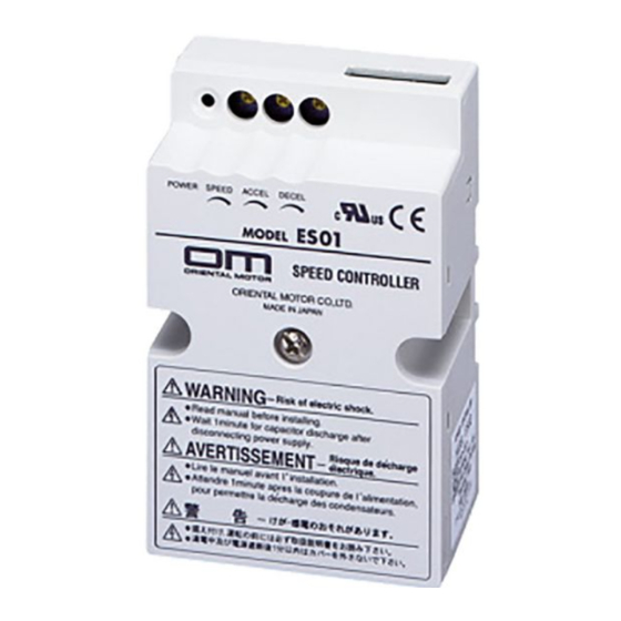
Speed Controller
ES01
ES02
OPERATING MANUAL
Thank you for purchasing an Oriental Motor product.
This Operating Manual describes product handling procedures and safety precautions.
● Please read it thoroughly to ensure safe operation.
● Always keep the manual where it is readily available.
Table of Contents
Before using the product .................. Page 2
Safety precautions ........................... Page 3
Installation .................................... Page 5
Connection and operation ............... Page 8
Inspection ....................................... Page 16
HP-5018-10
Advertisement

Related Manuals for Oriental motor ES01


Summary of Contents for Oriental motor ES01
-
Page 1: Table Of Contents
HP-5018-10 Speed Controller ES01 ES02 OPERATING MANUAL Table of Contents Before using the product ……………… Page 2 Safety precautions ……………………… Page 3 Installation ……………………………… Page 5 Connection and operation …………… Page 8 Inspection ………………………………… Page 16 Troubleshooting and remedial actions ………………………… Page 17 Thank you for purchasing an Oriental Motor product. -
Page 2: Before Using The Product
(control the speed of) dedicated speed control motors based on closed-loop phase contr ol. The World K Series and V Series speed control motors (6 W ~ 90 W) can be driven by the ES01/ES02. Refer also to the operating manual for the applicable motor. -
Page 3: Safety Precautions
Safety precautions The precautions described below are intended to prevent danger or injury to the user and other personnel through safe, correct use of the product. Use the product only after carefully reading and fully understanding these instructions. Connection Warning Keep the speed controller’s input-power voltage ●... - Page 4 ■Warning indication Caution Warnings are indicated on the cover of the speed controller. Always observe such information General when handling the speed controller. Do not use the speed controller beyond its ● specification, or electric shock, injury or damage to equipment may result. Installation Keep the area around the speed controller free ●...
-
Page 5: Installation
Installation Location for installation The speed controller is designed and manufactured for installation in equipment. Install it in a well-ventilated location that provides easy access for inspection. The location must also satisfy the following conditions. Check ventilation if the ambient temperature of the speed controller exceeds 40°C (104°F). Inside an enclosure that is installed indoors (provide vent holes) ●... - Page 6 ■Installing and wiring ◆Connecting mains filter Connect a mains filter specified in the table below, or the equivalent, to the AC input line, in order to suppress the noise generated from the speed controller. TDK Corporation ZAG2210-11S EPCOS AG B84112-B-B110 Schaffner EMC FN2330Y-10-06, FN2310X-10-06 Tyco Electronics CORCOM...
- Page 7 To ground a shielded cable, use a metal cable clamp or similar device that will maintain contact with the entire circumference of the shielded cable. Attach a cable clamp as close to the end of the cable as possible, and connect it to an appropriate grounding point as shown in the figure. Shielded cable Cable clamp ...
-
Page 8: Connection And Operation
Connection and operation Connect the speed controller to the power supply, motor and switches according to the following procedure: Loosen the cover screw (M4, one location) at the center of the cover, and remove the cover. Connect each terminal. Install the cover and secure it with the cover screw (M4, one location). Tightening torque: 0.7 N·m (99 oz-in) See “Installing and wiring in compliance with EMC directive”... - Page 9 Use an independent power source for the speed controller, and separate the control and power lines. Specifications of the switches and fuse Power supply/Voltage 100 V/110 V/115 V (ES01) 200 V/220 V/230 V (ES02) 125 VAC 10 A 250 VAC 5 A SW2, SW3 18 VDC 1 mA...
- Page 10 AWG18(0.75 mm ) min. MOTOR Motor AWG18(0.75 mm Blue Blue min. Capacitor Frame ground ES01 100 VAC 50/60 Hz Fuse 110 VAC 60 Hz 115 VAC 60 Hz White Power supply AWG18(0.75 mm ) min. ES02 200 VAC 50/60 Hz...
- Page 11 S1 S2 S3 S4 S5 S6 POWER SPEED ACCEL DECEL INT-VR STOP EXT-VR BRAKE MOTOR AWG18(0.75 mm ) min. Frame ground ES01 100 VAC 50/60 Hz Fuse 110 VAC 60 Hz Blue Blue 115 VAC 60 Hz Power supply AWG18 ES02 (0.75 mm...
- Page 12 Operation The timing chart below shows an example of switching between two speed levels when the high speed and low speed are selected via the internal and external speed potentiometers, respectively (see page 15). Switching between Acceleration/ ∗ Run/Stop immediately two speed levels/Stop Deceleration operation High speed...
- Page 13 ■Setting the speed Use the internal speed potentiometer. The 2000 setting range is from 90 to 1400 r/min at 50 Hz 60 Hz or 90 to 1600 r/min at 60 Hz. Short the speed 50 Hz potentiometer input terminals S4 and S5. 1500 Turning the potentiometer clockwise will set a faster speed.
- Page 14 ■Deceleration The deceleration function is actuated at natural stop or when the speed is switched to the lower setting in a two-level speed control. Turning the deceleration time potentiometer clockwise will increase the set time. The factory setting is 0 (no deceleration). Deceleration time potentiometer Deceleration time potentiometer position- speed characteristics (typical value)
- Page 15 ■Mounting the external speed potentiometer Insert the insulated sheet and potentiometer into the hole of the mounting plate, as illustrated below. Insert the dial plate and toothed washer in position and lock them with nuts. Tightening torque: 0.45 N·m (63 oz-in) max. Mount the knob and lock it using the set screw (M4).
-
Page 16: Inspection
Repeated operation/braking cycle When running/braking of the motor is repeated in short cycles, the rise in motor temperature will increase and the continuous-operation time will be limited. Use the following values as a guideline: Motor output Repetition cycle 6 ~ 40 W 2 seconds min. -
Page 17: Troubleshooting And Remedial Actions
Troubleshooting and remedial actions During motor operation, the motor or speed controller may fail to function properly due to an improper speed setting or wiring. When the motor cannot be operated correctly, refer to the contents provided in this section and take appropriate action. If the problem persists, contact your nearest office. Certain items must be checked with the power on. - Page 18 • Please contact your nearest Oriental Motor o ce for further information. Singapore Korea Technical Support Tel:(800)468-3982 Tel:1800-8420280 Tel:080-777-2042 8:30 to 5:00 , P.S.T. (M-F) A.M. P.M. www.orientalmotor.com.sg www.inaom.co.kr 7:30 to 5:00 , C.S.T. (M-F) A.M. P.M. www.orientalmotor.com Tel:1800-806161 Hong Kong Branch Tel:+55-11-3266-6018 www.orientalmotor.com.my...
Need help?
Do you have a question about the ES01 and is the answer not in the manual?
Questions and answers