Oriental motor DSC Series Operating Manual
Ac speed controller
Hide thumbs
Also See for DSC Series:
- Operating manual (44 pages) ,
- Operating manual (44 pages) ,
- Operating manual (44 pages)
Table of Contents
Advertisement
HP-5075
AC Speed Controller
DSC Series
OPERATING MANUAL
Thank you for purchasing an Oriental Motor product.
This Operating Manual describes product handling procedures and safety precautions.
• • Please read it thoroughly to ensure safe operation.
• • Always keep the manual where it is readily available.
Advertisement
Table of Contents

Related Manuals for Oriental motor DSC Series


Summary of Contents for Oriental motor DSC Series
- Page 1 AC Speed Controller DSC Series OPERATING MANUAL Thank you for purchasing an Oriental Motor product. This Operating Manual describes product handling procedures and safety precautions. • • Please read it thoroughly to ensure safe operation. • • Always keep the manual where it is readily available.
-
Page 2: Table Of Contents
Table of contents Introduction ............3 Function ...............23 Before using the product ........3 Functions list ............23 Description of operating manual ...... 3 Operation panel transitions ......24 Safety precautions ..........4 Items that can be monitored ......26 Setting the operation data .........26 Preparation ............ -
Page 3: Introduction
The product described in this manual has been designed and manufactured to be incorporated in general industrial equipment. Do not use for any other purpose. Oriental Motor Co., Ltd. is not responsible for any damage caused through failure to observe this warning. 1.2 Description of operating manual •... -
Page 4: Safety Precautions
Safety precautions 2 Safety precautions The precautions described below are intended to prevent danger or injury to the user and other personnel through safe, correct use of the product. Use the product only after carefully reading and fully understanding these instructions. WARNING Handling the product without observing the instructions that accompany a "Warning"... -
Page 5: Preparation
Operating manual (this document)..1 copy Capacitor cap........1 piece 3.2 How to identify the product model DSCD 25 JA ① Speed controller type DSCD: DSC Series speed controller ① ② ③ 15 W : 25 W ② Output power : 40 W... -
Page 6: Products Possible To Combine
Preparation 3.4 Products possible to combine Be sure to match the output power and power supply voltage of the motor with those of the speed controller. Also use a capacitor in the specified combination. The box ( o ) in the model name indicates the number representing the gear ratio. In the case of the round shaft type, enter "A"... -
Page 7: Names And Functions Of Parts
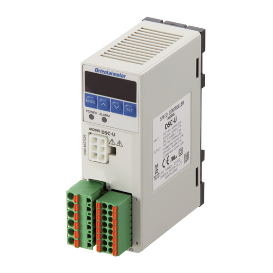
Preparation 3.5 Names and functions of parts Display Operation panel Operation keys Protective lm POWER LED (Use after removing the protective lm.) (Green) ALARM LED (Red) Motor connector (CN3) Control circuit connector Main circuit connector (CN4) (CN1) Sink logic/Source logic select switch (SW1) DIN lever Reference Item Display... -
Page 8: Installation
Installation 4 Installation This chapter explains the installation location and installation methods. 4.1 Installation location The speed controller described in this manual has been designed and manufactured to be incorporated in general industrial equipment. Install it in a well-ventilated location that provides easy access for inspection. The location must also satisfy the following conditions: •... - Page 9 Installation „ Installation method „ • Mounting to DIN rail Use a DIN rail 35 mm (1.38 in.) wide to mount the speed controller. Hook Pull down the DIN lever of the speed controller until it locks, and push in the speed controller with hanging the hook at the rear to the DIN rail, and then lift the DIN lever.
-
Page 10: Installing The Capacitor
Installation 4.3 Installing the capacitor Before mounting the provided capacitor, check that the capacitor’s capacitance matches that stated on the motor’s name plate. Install the capacitor securely using M4 screw (not included). Ø4.3 mm (0.17 in.) • • Do not let the screw tightening torque exceed 1 N·m (8.8 lb-in) to prevent damage to the mounting foot. Note •... -
Page 11: Connection
Connection 5 Connection This chapter explains how to connect the speed controller, power supply, motor and others. When operating a motor, be sure to connect the control DC power supply in addition to the AC power supply. Motor Speed controller Grounding Control DC power supply 24 VDC±10%... -
Page 12: Connecting The Motor And Speed Controller
Connection „ CN1 pin assignment „ Pin No. Description Description CAPACITOR Capacitor Connect the capacitor. N.C. Not connected. Connect a live wire. 100-230V〜 AC power supply Connect a neutral wire. Connect a grounding wire. „ Connecting the capacitor „ Connect the included capacitor to the speed controller. Capacitor cap If crimp terminals are used, select the FASTON Terminals 187 Series (TE Connectivity). -
Page 13: Connecting The Control Dc Power Supply And I/O Signals
Connection „ Speed controller „ Ground the speed controller using the FG terminal of the CN1 (main circuit connector). Grounding 5.4 Connecting the control DC power supply and I/O signals Connect the control DC power supply and I/O signals to the CN4. Insert the lead wire while pushing the button of the orange color with a For the control DC power supply, use a power supply with reinforced insulation screwdriver. - Page 14 Connection • Connection example for I/O signals The figure shows a connection example when the product is operated with the sink logic setting using relays, switches and other contact switches. When operating and stopping the product using a programmable controller, or when using source logic, refer to p.15. Pin No.1 +24 V 24 VDC±10% Pin No.2 0 V (GND)
-
Page 15: Connection Example For I/O Signals And Programmable Controller
Connection 5.5 Connection example for I/O signals and programmable controller Figure viewed from the lower face Set the input logic to the sink logic side or source logic side in accordance with of the speed controller the programmable controller used with the speed controller. It is set using the SW1 as shown in the figure. Sink logic (SINK) is set at the time of shipment. -
Page 16: Operation
Operation 6 Operation This chapter explains how to operate the motor and speed controller. Installing the speed controller Connecting the motor p.12 Connecting the control Connecting the AC power DC power supply and I/O signals supply and capacitor p.13 p.11 6.1 Power ON Turn on the power after completing the connection. -
Page 17: Starting, Stopping
Operation 6.2 Starting, stopping When either the FWD input or REV input is turned ON after setting the rotation speed, the motor will rotate at the specified speed. If the signal (FWD input or REV input) which has been turned ON is turned OFF while the motor rotates, the motor will decelerate to a stop according to the specified deceleration time. -
Page 18: X84; Setting Method Using The Operation Panel
Operation „ Setting method using the operation panel „ The rotation speed can be set while rotating the motor, and it can also be set in the motor standstill state. This section explains how to set the rotation speed while rotating the motor as an example. Example: Set the rotation speed to 1000 r/min from 0 r/min Setting method Panel display... -
Page 19: Setting The Acceleration Time And Deceleration Time
Operation 6.4 Setting the acceleration time and deceleration time The acceleration time and deceleration time can be adjusted to prevent the load from receiving a shock upon starting, stopping, or changing in speed. Refer to p.26 for how to set each operation data using the operation panel. Setting range: 0 to 15.0 seconds The actual acceleration time and deceleration time against the setting vary depending on the inertial load, frictional load, set rotation speed or motor output power. -
Page 20: Timing Chart
Operation 6.6 Timing chart This is an example of a timing chart for a basic operation. Example: 1200 r/min is set in the operation data No.0, and 100 r/min is set in the operation data No.1. Run/ Speed change/ Run/ Instantaneous Run/ Stop Instantaneous stop... -
Page 21: Operating At Two Or More Speeds (Multi-Speed Operation)
Operation 6.8 Operating at two or more speeds (multi-speed operation) The multi-speed operation can be performed by setting the rotation speed Low speed and switching the ON-OFF status of the M0 and M1 inputs. High speed „ Data setting method „ (example: rotation speed) Power ON Panel display Rotation speed: 0 r/min (Initial value) Press... -
Page 22: Adjusting The Rotation Speed Of Two Or More Motors By A Single Setting Device (Multi-Motor Control)
Operation 6.9 Adjusting the rotation speed of two or more motors by a single setting device (multi-motor control) Two or more motors can be operated at the same speed using a single variable resistor or external DC voltage. Set the "external speed command input" parameter to "ON (enable)," and turn the M0 input and M1 input OFF. Refer to p.27 for parameter. -
Page 23: Function
Function 7 Function 7.1 Functions list The following functions are available for this product. Reference Function Description page Displays the rotation speed of the motor output shaft. Rotation speed Displays the rotation speed of the gearhead output shaft. Fixes the display of the lowest digit to "0." Displays the transfer speed of the conveyor drive. -
Page 24: Operation Panel Transitions
Function 7.2 Operation panel transitions Power ON Power ON • When the AC power supply is turned on, the POWER LED (green) is lit. • When the DC power supply is turned on, the display on the operation panel is lit. Rotation speed teaching function Rotation speed Change the rotation speed with... - Page 25 Function Overview of the operation panel Edit lock function The operation panel can be locked so that the data cannot be changed. : Switches the operation mode. Moves to the upper level. Perform the following action on the top screen in each mode. Lock: Press and hold for 5 seconds : Changes the setting value.
-
Page 26: Items That Can Be Monitored
Function 7.3 Items that can be monitored Operation mode: Monitor mode Item Display Monitor item • • The rotation speed of the motor shaft is displayed. • • When the "speed reduction ratio" parameter is set, the rotation speed of the gear output shaft or Rotation the conveyor transfer speed is displayed. -
Page 27: Setting The Parameters
Function 7.5 Setting the parameters „ Parameter list „ Operation mode: Parameter mode Initial Item Display Description Setting range value Setting the speed reduction ratio with respect to the rotation speed of the motor output shaft can display the Speed reduction ratio speed being converted by the speed reduction ratio. -
Page 28: X84; Displayed Digit Number When Setting The Speed Reduction Ratio Or Speed Increasing Ratio
Function • „ Displayed digit number when setting the speed reduction ratio or speed increasing ratio The number of significant figures for the integer part is changed if the speed reduction ratio or speed increasing ratio is set, so the digit number displayed on the panel will also be changed. Setting value of the speed reduction Display digit on the panel ratio and speed increasing ratio... -
Page 29: X84; Description Of I/O Signals That Can Be Assigned
Function • „ Description of I/O signals that can be assigned 6 input signals and 2 output signals out of the following signals can be assigned. Signal Terminal Signal name Description When the FWD input is turned ON, the motor output shaft rotates in the forward direction according to the set acceleration time. -
Page 30: Alarms
∗1 ● Data became no longer writable or readable. your nearest Oriental Motor sales office. If the FWD input or REV input which has The power supply was turned on while the FWD input or been turned ON is turned OFF, the alarm REV input was being ON. - Page 31 • • If the product does not operate properly after the control DC power supply is turned on again, internal Note circuit damage is suspected. Contact your nearest Oriental Motor sales office. • • Continuing the operation without removing the cause of the alarm may cause damage to equipment.
-
Page 32: Warnings
Alarms 8.2 Warnings The warning types and records can be displayed on the monitor mode. When a warning generates, the WNG output is turned ON. The WNG output is not assigned to the output terminal at the time of shipment. Refer to "Description of I/O signals that can be assigned" on p.29. The warning records will be cleared by turning off the control DC power supply. -
Page 33: Troubleshooting
When the motor cannot be operated properly, refer to the contents provided in this chapter and take appropriate action. If the problem persists, contact your nearest Oriental Motor sales office. Certain items must be checked with the power on. Perform inspections carefully not to touch the live part Note such as connection part of the motor and speed controller. -
Page 34: Maintenance And Inspection
It is recommended that periodic inspections for the items listed below are conducted after each operation of the motor. If an abnormal condition is noted, discontinue any use and contact your nearest Oriental Motor sales office. • • Conduct the insulation resistance measurement or dielectric strength test separately on the motor and the Note speed controller. -
Page 35: Accessories (Sold Separately)
„ External potentiometer „ This potentiometer is used to set and adjust the motor rotation speed remotely. Model: PAVR2-20K Couplings and mounting brackets are provided as accessories (sold separately). Check on the Oriental Motor Website for the product specifications. −35−... -
Page 36: Regulations And Standards
Regulations and standards 12 Regulations and standards 12.1 UL Standards, CSA Standards This product is recognized by UL under the UL and CSA Standards. Certification body/Standards Applicable standards file number UL 508 UL / UL File No.E91291 CSA C22.2 No.14 12.2 EU Directives „ CE Marking „ This product is affixed the CE Marking under the Low Voltage Directive and EMC Directive. -
Page 37: Emc Directive
• • Use an accessory connection cable (sold separately) when extending the wiring distance between the motor and speed controller. The EMC testing is conducted using the Oriental Motor connection cable. −37−... - Page 38 Regulations and standards „ Example of installation and wiring „ Motor Speed controller Motor cable [maximum 10.5 m (34.4 ft.)] Grounding Surge Main arrester lter Cable AC power supply clamp cable Control cable [2 m (6.6 ft.) or less] Grounding Grounding Grounding Grounding...
-
Page 39: Specifications
Specifications 13 Specifications 13.1 Specifications Check on the Oriental Motor Website for the product specifications. 13.2 General specifications Ambient temperature 0 to +50 °C [+32 to +122 °F] (non-freezing) Ambient humidity 85% or less (non-condensing) Altitude Up to 1000 m (3300 ft.) above sea level No corrosive gas, dust, water or oil. - Page 40 If a new copy is required to replace an original manual that has been damaged or lost, please contact your nearest Oriental Motor branch or sales office. • • Oriental Motor shall not be liable whatsoever for any problems relating to industrial property rights arising from use of any information, circuit, equipment or device provided or referenced in this manual.
Need help?
Do you have a question about the DSC Series and is the answer not in the manual?
Questions and answers