
Related Manuals for Estun E10

Summary of Contents for Estun E10
-
Page 1: Operation Manual
E10 Numerical Display System Operation Manual Version: V1.15 南京埃斯顿数字技术有限公司/ESTUN Digital Technology Co., Ltd. 南京江宁经济开发区将军南路 155 号 邮编 211100 电话:025-52785866 No.155,Jiang Jun Road South,Jiang Ning Development Zone,Nanjing P.R.C 211100... -
Page 2: Table Of Contents
3.6 System debugging steps ............6 3.6.1 Preparation before debugging .......... 6 3.6.2 Debugging ............. 7 3.6.3 Actual processing ............. 7 3.7 E10 electrical design typical application example ......8 Chapter 4 Operation Functions ............ 10 4.1 Operation panel ............10 4.2 introduction ............... -
Page 3: Chapter 1 Introduction
E10 Operation Manual V1.15 Chapter 1 Introduction Thanks for buying E10 CNC controllers. Before using our E10 CNC controllers, I suggest you read this manual very carefully. Compared with conventional CNC units, E10 has much better cost performance, good looks and higher brightness display, in addition, it also has many special functions to meet the... -
Page 4: Chapter 2 Specification
E10 Operation Manual V1.15 Chapter 2 Specification Technical Specification 1、Mounting dimension: Outer housing mount: 186*138*84 Panel mount: 171*122*84 2、Panel specification: 2 rows of [6*7] segment LED display Filmy key-presses of high quality metal spring plate 3、Axis specification: Stroke range of X axis... -
Page 5: Chapter 3 Installation And Debugging
In order to avoid any failure, please do not take down the system privately,. Electronic components of E10 system are all sensitive to static electricity. It will not be allowed to fall into any foreign body insertion or touch the control circuit boards of E10 system. -
Page 6: Rear Panel
E10 Operation Manual V1.15 3.5 Rear Panel 3.5.1 Rear panel On the rear panel (Figure 3-1) , there are input instructions, output instructions, encoder interface and connection port (wirings see appendix). The significance of the indicator light will make the following introduction. -
Page 7: Input Instructions
------------------------ indicator light goes out, and Y-axis position is larger than the max. 3.5.6 Encoder interface E10 system panel has two 9-pin encoder interfaces: X-axis encoder interface and Y-axis encoder interface. From top-down look, the first for the X-axis encoder interface; and the second for the Y-axis encoder interface. -
Page 8: Debugging
E10 Operation Manual V1.15 3.6.2 Debugging 1. You must check power and ground wire as well as other wiring is correct before power on. 2. Check if system is working properly, and power off immediately if not. 3. Check the digital interface, all digital tubes should be lit in this time. -
Page 9: E10 Electrical Design Typical Application Example
E10 Operation Manual V1.15 3.7 E10 electrical design typical application example +24V OUT2 OUT4 OUT3 OUT1 +24V Electrical Design Description: The input access method: 1, has to find a reference point function: Shearing machine : input IN1 (normally open signal) as the shear count signal input, then input IN2 accesses reference point. - Page 10 E10 Operation Manual V1.15 Bending machine: the output OUT1,OUT2,OUT3 and OUT4 access relay coil externally. When E10 hasn’t soft limit function: Shearing machine : the output OUT1, OUT2, OUT3, OUT4 can be an external relay coil as a time relay output.
-
Page 11: Chapter 4 Operation Functions
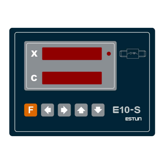
E10 Operation Manual V1.15 Chapter 4 Operation Functions 4.1 Operation panel 4-1 Front panel Page 10 of 28... -
Page 12: Introduction
E10 Operation Manual V1.15 4.2 introduction 4.2.1 LED lamp There’s one LED lamp in the front panel: LED lamp behind the first line digital display ------------Alarm LED. It will be lid if there’s no one-side positioning on X-axis,which means screw rod gap still remains. -
Page 13: Digital Display
E10 Operation Manual V1.15 4.2.3 Digital display There are 12 characters displayed in two lines Display in normal status: The first line displays X-axis position. The second line displays Y-axis position (shearing counters displayed in shearing machine .) Display in teach-in parameter and machine tool parameter modifications: The first line displays parameter numbers. - Page 14 E10 Operation Manual V1.15 Page 13 of 28...
-
Page 15: Chapter 5 Parameters
E10 Operation Manual V1.15 Chapter 5 Parameters 5.1 Set a parameter Power on, press to enter each parameter interface. Then the first line of digital display shows the parameter num and the second line shows the value of the parameter. Only the value of flashing digit can be edited. -
Page 16: Counting Parameters
(current counting)will be set the same value automatically. When the value of CNT01(current counting)decrease to ‘0’, counting arrives and port exports. 3、 When parameter CNT02(preset counting)is set as ‘0’, E10 will count and not export any output signals. 4、 If the parameter of port function for counting arrived is not set, then there will be no output. - Page 17 E10 Operation Manual V1.15 Range:0 — 999999 Unit:Display Unit Default :0 Teach-in parameters for shearing machine: PAC 01. X-axis current position Display X-axis current position Range:0 — 999999 Unit:Display Unit Default :0 Page 16 of 28...
-
Page 18: Chapter 6 Machine Parameters
E10 Operation Manual V1.15 Chapter 6 Machine Parameters 6.1 Set machine parameters ; 1、Press to enter machine parameter interface. to confirm the edit parameter ‘PAN-00’, then input pin number 2、Press ‘ ’ ; ; 3、Press to confirm, and the interface shows 4、The first line of digital display shows the parameter num and the second line shows... - Page 19 E10 Operation Manual V1.15 PAN09 Counter direction of X-axis PAN10 Counter direction of Y-axis X-axis min position PAN11 X-axis max position PAN29 6000.0 Y-axis min position PAN31 5.00 Y-axis max position PAN49 600.00 Recover the default value PAN56 PAN57 Outputs definition...
- Page 20 E10 Operation Manual V1.15 PAN31 Outputs definition PAN32 X-axis reference point searching set PAN33 X-axis reference point value PAN34 IN1 level mode PAN35 IN2 level mode PAN36 OUT1 level mode PAN37 OUT2 level mode PAN38 OUT3 level mode PAN39 OUT4 level mode...
- Page 21 E10 Operation Manual V1.15 Unit:None Default:4 Description: the same as PAN 03 PAN 05. X-axis dividing factor Range :1 - 9999 Unit:None Default:1 Description: dividing factor = screw rod pitch × deceleration ratio between encoder and transfer screw rod. F = multiple factor / dividing factor.
- Page 22 E10 Operation Manual V1.15 Default:5.0 Description :X-axis min position。 PAN 29. X-axis max position Range :0 - 999999 Unit:Displays Unit Default:6000.0 Description :X-axis max position PAN 31. Y-axis min position Range :0 - 999999 Unit:Display Unit Default:5.00 Description :Y-axis min position PAN 49.
- Page 23 E10 Operation Manual V1.15 Description: When the function of searching for Y-axis reference point is available, the parameter sets the value as a reference point. PAN 62. Input level mode Range: 0 - 1 Unit: Default: 0 Description: level mode selection of input IN1, 0: always; 1: normally close.
- Page 24 E10 Operation Manual V1.15 Unit: Default: 0 Description: function choice of Relay 1, the input port trigger selection, 0: prohibited; 1: IN1 trigger; 2: IN2 trigger. PAN 73. Relay functionality mode Range: 0 - 2 Unit: Default: 0 Description: function choice of Relay 2, the input port trigger selection, 0: prohibited; 1: IN1 trigger;...
-
Page 25: Appendix 1 Q&A
E10 Operation Manual V1.15 Appendix 1 Q&A 1. Power on, the system has no display. Check the power supply access is correct. 2. If the machine is in run-time, the location of axis does not show or change, check the encoder cable is well-connected. -
Page 26: Appendix 2 Plastic Crust Installation
E10 Operation Manual V1.15 Appendix 2 Plastic crust Installation unit: mm Page 25 of 28... - Page 27 E10 Operation Manual V1.15 unit: mm Page 26 of 28...
-
Page 28: Appendix 3 Panel Installation
E10 Operation Manual V1.15 Appendix 3 Panel Installation unit:mm Page 27 of 28...
Need help?
Do you have a question about the E10 and is the answer not in the manual?
Questions and answers