Advertisement
Quick Links
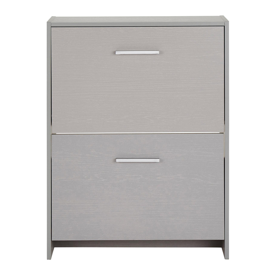
Shoe Storage Cabinet
Assembly Instructions
045 xx 5525
- Please keep for future reference
Dimensions
Width - 66.4cm
Depth - 24cm
Height - 87cm
Important -
Please read these instructions fully before starting assembly
If you need help or have damaged or missing parts, call the Customer Helpline: 01709 534 123
Please turn to back page for important information when contacting Customer Helpline.
Rev B - 20/03/2017
Advertisement

Related Manuals for JD Williams Norton Shoe Rack


Summary of Contents for JD Williams Norton Shoe Rack
- Page 1 Shoe Storage Cabinet Assembly Instructions 045 xx 5525 - Please keep for future reference Dimensions Width - 66.4cm Depth - 24cm Height - 87cm Important - Please read these instructions fully before starting assembly If you need help or have damaged or missing parts, call the Customer Helpline: 01709 534 123 Please turn to back page for important information when contacting Customer Helpline.
- Page 2 Safety and Care Advice Important - Please read these instructions fully before starting assembly Do not stand or put weight on Check you have all the We do not the product, this could cause components and tools listed on recommend the damage.
- Page 3 Components - Panels Please check you have all the panels listed below Important - Thick lines indicate finished edges Packing Panel (63.4x103cm) 8379 Code - Not required in build of unit. Left hand end Right hand end (87x24.2cm) (87x24.2cm) Code - 9808 Code - 9809 Shoe flap x 2 (63.4x24cm)
-
Page 4: Components - Exploded View
Components - Exploded View Important - Thick lines indicate finished edges 8315 9808 8322 8320 8320 0709 8321 8320 8320 9809 0709 8321 8316... - Page 5 If you have damaged or missing components, call the Components-Fittings Customer Helpline: 01709 534 123 Please turn to back page for important information when contacting Customer Helpline. Please check you have all the fittings listed below Note: The quantities below are the correct amount to complete the assembly, In some case more fittings may be supplied than are required.
- Page 6 Assembly Instructions Step 1 Seperate all components and ensure all plastic sprue is removed from fittings Step 2 Fittings you will need for this step: Fitting pivot & shelf pin to left & right end panels (x4) (x4) 9808 9809 Note: Use a hammer to knock in pivots and shelf pins...
- Page 7 Assembly Instructions Fittings you will need for this step: Step 3 Attach plinth & top panel to right hand end panel. (x4) Locate screw through hole in rh end panel and screw 9809 into hole in plinth 8316 Raw Face 9809 Locate screw through...
- Page 8 Assembly Instructions Step 5 Square unit up Important: DIAG 1 Ensure a tape measure is used to square up unit! Before securing the back 9809 it is necessary to square up the unit. DIAG 2 You can do this by measuring between 9808 XX - XX and YY - YY...
- Page 9 Assembly Instructions Fittings you will need for this step: Step 7 Important: Before commencing (x12) ensure step 1 (x2) has been followed (x2) fully. Attaching left and right hand brackets to flap Align the left hand bracket with the pre-drilled holes of flap 0709 panel .Secure...
- Page 10 Assembly Instructions Step 9 Attach flap assemblies Important: 2 people required. Carefully stand the unit upright. Position the flap into the main unit as shown. Warning. Ensure fitting already inserted in end panels is not dislodged. Carefully pull the brackets in the direction shown by the arrows.
- Page 11 Assembly Instructions Fittings you will need for this step: Step 9 - Continued ( diag 1 ) To fix the flap assemblies to the lh end panel 9808 and right (x2) (x2) hand end panel 9809 through lh and rh brackets Firstly, using a screwdriver insert into...
- Page 12 Assembly Instructions Fittings you will need for this step: Step 10 Attach handles Secure handles (x4) (x2) 0709 flap panels using bolts 0709...
- Page 13 Assembly Instructions Fittings you will need for this step: Step 11 Cover exposed screw (x8) heads using caps...
- Page 14 Assembly Instructions Step 12 Fittings you will need for this step: Fixing to wall We recommend that this (x2) (x1) unit is fixed to a suitable wall to prevent possible overbalancing. We have included a fixing bracket for this. No fixing screws are provided as they will need to suit the wall type, and the length of...
- Page 15 Congratulations! Your unit is complete Note: Please turn over for important information.
- Page 16 Important Information If you need help or have damaged or missing parts, call the Customer Helpline: 01709 534 123 Simply contact us on CUSTOMER HELPLINE : 01709 534123 Between 8am - 4.30pm Monday to Thursday and 8am - 2.30p.m friday. Your statutory rights are not affected. Please have the following information: Unit Description, Product Code, Product Colour, Place of Purchase, Catalogue Ref.
Need help?
Do you have a question about the Norton Shoe Rack and is the answer not in the manual?
Questions and answers