Advertisement
Quick Links
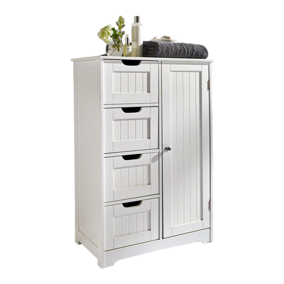
NEW ENGLAND STORAGE CABINET
Dimensions
No. people
Width: 56cm
Depth: 30.5cm
Height: 82cm
Important - Please read these instructions fully before starting assembly
If you need help of have damaged or missing parts, calls the JDW Customer Helpline: 0871 231 2000
Assembly Instructions
Please keep for future reference
Assembly Time
1 hour
(approx.)
464/3944
CAT NO: QN912
CAT NO: UM241
Advertisement

Related Manuals for JD Williams AT HOME NEW ENGLAND


Summary of Contents for JD Williams AT HOME NEW ENGLAND
- Page 1 Assembly Instructions Please keep for future reference 464/3944 NEW ENGLAND STORAGE CABINET CAT NO: QN912 CAT NO: UM241 Dimensions No. people Assembly Time Width: 56cm 1 hour Depth: 30.5cm (approx.) Height: 82cm Important - Please read these instructions fully before starting assembly If you need help of have damaged or missing parts, calls the JDW Customer Helpline: 0871 231 2000...
- Page 2 Safety and Care Advice Important – Please read these instructions fully before starting assembly • Check you have all the • During assembly do not stand • We do not components and tools listed on or put weight on the product, recommend the use page 2 this could cause damage.
- Page 3 Components - Panels Please check you have all the panels listed below 80. 5X28. 8x1. 5cm 71. 6x28. 5x1. 2cm 56x30. 5x1. 5cm 80. 5X28. 8x1. 5cm 24. 5x4. 5x1. 2cm 24. 5x4. 5x1. 2cm 10X2 11x4 12x8 50x28. 5x1. 2cm 71.
- Page 5 Assembly Instructions Step 1 1. Into the underside of Top Panel 1 insert 6 x Male Camlocks B as shown. Connect magnetic catch E using 2 x Screw 2. Into Base panel 8 insert 2 x Male Camlocks Step 2 Connect 2 x Drawer sides 12 to 1 x Drawer Back 13 using 4 x...
- Page 6 Assembly Instructions Step 4 1. Insert 2 x Dowels into the top and bottom of middle panel 4 as shown 2. Insert 4 x Dowels into the edge of Base panel 8 3. Into Front Plinth 9 insert 4 x Dowels A 4.
- Page 7 Assembly Instructions Step 7 1. Into Right Side panel insert 3 x male camlocks in position shown 2. Connect Parts as shown and insert 3 x Female Camlocks. Tighten with a Phillips Screwdriver Step 8 1. Into Door 7 insert 2 x Hinge Pins L 2.
- Page 8 Assembly Instructions Step 9 1. To door 7 connect Catch Plate F using 2 x Screws H 2. Connect your choice of handle, either handle I or S using screw J 3. Insert 8 x Shelf Supports as shown Step 10 1.
- Page 9 Assembly Instructions Step 12 The unit is floor standing, but it is recommended that the unit is secured to the wall. 1. On the reverse of the unit, in position shown, fix 1 x Wall Straps using 1 x Screws L 2.
Need help?
Do you have a question about the AT HOME NEW ENGLAND and is the answer not in the manual?
Questions and answers