
Related Manuals for Harmar Mobility SL600 HD


Summary of Contents for Harmar Mobility SL600 HD
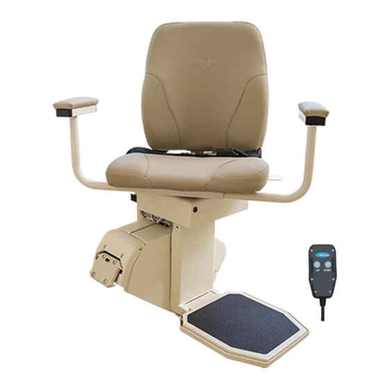
- Page 1 PINNACLE STAIR LIFT SL600 HD INSTALLATION & SERVICE MANUAL 31JAN2020 | P/N: 75403 Rev C...
-
Page 3: Table Of Contents
HEAVY DUTY STAIR LIFT TABLE OF CONTENTS Table of Contents INTRODUCTION ..........4 Device Name: Pinnacle SL600HD Stair Lift ....4 Read and Understand .............4 Technical Specifications ..........4 SAFETY ..............5 Safety Definitions ............5 Required Practices ............5 PREPARATION ..........6 Required Tools ..............6 Unpacking the Lift ............6 Checking the Box Contents ...........7... -
Page 4: Introduction
Indoor Use Only Indications of Use: The intended use of the Pinnacle Rated Load: 600 lb SL600 HD Stair Lift is to assist the transfer of patients Incline Limits: 32˚ to 45˚ or mobility impaired persons, up and down levels of a... -
Page 5: Safety
HEAVY DUTY STAIR LIFT: SECTION 2 SAFETY Section 2 Safety SAFETY DEFINITIONS REQUIRED PRACTICES NOTE: Installation of this lift requires one person, as This safety alert symbol appears with long as the one person follows installation instructions, safety statements. It means attention, has completed training, has obtained certification on become alert, your safety is involved! installation, is able to instruct the user on the correct... -
Page 6: Preparation
HEAVY DUTY STAIR LIFT: SECTION 3 PREPARATION Section 3 Preparation UNPACKING THE LIFT Installations may vary to some degree, but below are the basic tools to have on hand for a Pinnacle Stair Lift installation. Never attempt to pick up the lift from If you have any questions, concerns or comments, the box, ground or on/off a vehicle please contact our Technical Service Department at... -
Page 7: Checking The Box Contents
HEAVY DUTY STAIR LIFT: SECTION 3 PREPARATION CHECKING THE BOX CONTENTS Before installing the lift, review each part against the packaging checklist to ensure that all parts have been included. If any parts are missing or damaged, immediately contact the dealer who sold the lift. DO NOT attempt to install or use a lift that has missing or damaged parts. -
Page 8: Preparation
HEAVY DUTY STAIR LIFT: SECTION 3 PREPARATION DETERMINE OVERALL RAIL Extension LENGTH (ONLY IF TRACK DID NOT 7" 9" 11" 13" COME PRE-CUT TO LENGTH) Horizontal intrusion on top landing 1. Determine obstructions that will affect the 3.9" 5" 6.1" 7.2"... -
Page 9: Installation
HEAVY DUTY STAIR LIFT: SECTION 4 INSTALLATION Section 4 Installation 6. Turn over joined rails and install the remaining two join fasteners and firmly tighten with 3/16" Allen wrench. Then slide track pieces down to cover the joint. RAIL INSTALLATION 7. -
Page 10: Chassis Installation
HEAVY DUTY STAIR LIFT: SECTION 4 INSTALLATION Place the other rail on the last step before the clearance, and hold the rail in place, secure the top landing, again tightening it so it touches the bottom bracket to the first step from the floor rear of the last step. -
Page 11: Final Rail Installation
HEAVY DUTY STAIR LIFT: SECTION 4 INSTALLATION 3. Use the installation switch (the black switch on the top of the chassis) to move the chassis at least two feet down the rail, pushing gently on the chassis to ensure the chassis does not pull any rack to the top. -
Page 12: Footrest & Seat Installation
HEAVY DUTY STAIR LIFT: SECTION 4 INSTALLATION FOOTREST & SEAT INSTALLATION 1. Remove footrest from box and use the installation switch to drive the chassis downward to a position about 6" clear of the floor. This provides a safe area to install and Figure 4-13 adjust the footrest. - Page 13 HEAVY DUTY STAIR LIFT: SECTION 4 INSTALLATION 6. Connect the footrest cable to the 6-pin connector on the chassis. See Figure 4-21. Figure 4-17 Secure the rear seat support to the footrest/ seat support using the two hex-head bolts and Figure 4-21 washers.
-
Page 14: Remote Control Programming
HEAVY DUTY STAIR LIFT: SECTION 4 INSTALLATION not green after testing sensors, turn the unit off and re-check all wire plugs. Turn the unit on again and re-check the LED indicator light cycle. When the LED indicator light remains green, the lift is ready to operate. -
Page 15: Final Testing
HEAVY DUTY STAIR LIFT: SECTION 4 INSTALLATION 5. Release the switch and the lift will come to an top of the chassis) in either direction. immediate stop. 4. Turn the red “ON/OFF” switch to the “ON” 6. Run the chair all the way up and down the rail position, and then release the install switch. - Page 16 HEAVY DUTY STAIR LIFT: SECTION 4 INSTALLATION Additional System Checks providing protection from obstructions on the rail. 1. After the successful testing of all safety 2. Safety stop switches are located in the switches, secure the seat belt, sit on the lift and footrest bottom pan providing protection from operate to the top of the stairs.
- Page 17 NOTES SL600HD Heavy Duty Stair Lift: Installation & Service Manual 31JAN2020 | P/N: 75403 REV C...
- Page 18 NOTES SL600HD Heavy Duty Stair Lift: Installation & Service Manual 31JAN2020 | P/N: 75403 REV C...
- Page 19 NOTES SL600HD Heavy Duty Stair Lift: Installation & Service Manual 31JAN2020 | P/N: 75403 REV C...
- Page 20 2075 47 Street | Sarasota, FL 34234 800.833.0478 harmar.com...
Need help?
Do you have a question about the SL600 HD and is the answer not in the manual?
Questions and answers
How much does it cost for WIRING HARNESS FOR A pinnacle chair lift?