
Related Manuals for Harmar Mobility Pinnacle SL300-PS


Summary of Contents for Harmar Mobility Pinnacle SL300-PS
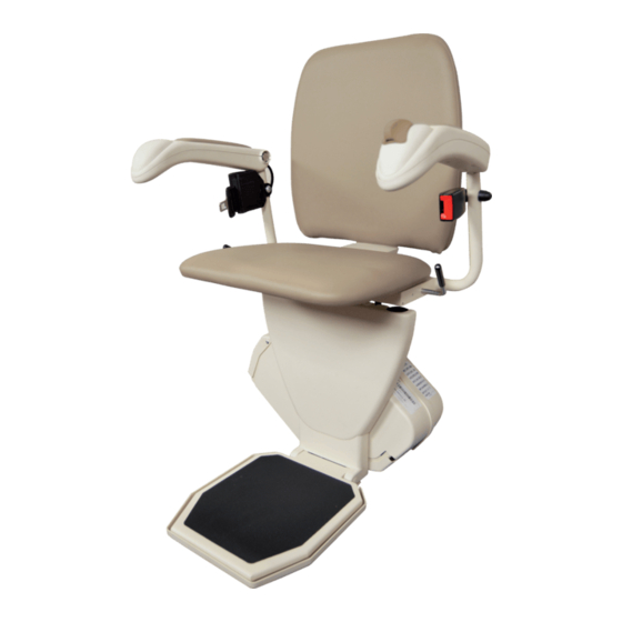
- Page 1 PINNACLE STAIRLIFT POWER SWIVEL POWER FOOTREST INSTALLATION & SERVICE MANUAL SUPPLEMENT 22MARCH24 | 630-00166-01-A...
-
Page 3: Table Of Contents
PINNACLE STAIRLIFT TABLE OF CONTENTS TABLE OF CONTENTS SAFETY .................... 4 Safety Definition ..........4 Environmental Cautions ........4 INTRODUCTION ................5 Device Name ............5 Read and Understand .......... 5 Warranty ............. 5 Technical Specifications ........5 Code Statement ..........5 PREPARATION ................ -
Page 4: Safety
PINNACLE STAIRLIFT: SECTION 1 SAFETY SECTION 1 SAFETY SAFETY DEFINITIONS ENVIRONMENTAL CONDITIONS This safety alert symbol appears with safety statements. It means attention, The technician shall assess the surrounding become alert, your safety and the conditions and verify that the location is acceptable safety of others are involved! Please before performing installation and/or servicing read and abide by the message that... -
Page 5: Introduction
PINNACLE STAIRLIFT: SECTION 2 INTRODUCTION SECTION 2 INTRODUCTION This supplement is intended to complement the SL300 and SL600 Installation + Service Manuals by providing additional installation and service details specifically tailored to the power swivel and power footrest options. It aims to enhance the understanding and execution of the installation and servicing processes for these components. -
Page 6: Preparation
PINNACLE STAIRLIFT: SECTION 3 PREPARATION SECTION 3 PREPARATION Installations may vary to some degree, but below SPECIFICATIONS are the basic tools to have on hand for a Pinnacle stairlift installation. POWER SWIVEL If you have any questions, concerns or comments, •... -
Page 7: Installation
PINNACLE STAIRLIFT: SECTION 4 INSTALLATION SECTION 4 INSTALLATION POWER SWIVEL REQUIRED TOOLS INSTALLATION (OPTION) • Flat blade screwdriver Follow these steps to disassemble the seat support • Vice grips or channel lock pliers assembly: • 13/32" wrench 1. Remove Plastic Shroud: Detach the plastic •... - Page 8 PINNACLE STAIRLIFT: SECTION 4 INSTALLATION • Ensure the motor plate is placed over the Magnet Harness and Cup Installation: motor, aligning the gear through the hole • Slide the white plastic washer onto the in the plate. See Figure 4-3. magnet harness, up to the switch.
- Page 9 PINNACLE STAIRLIFT: SECTION 4 INSTALLATION • Use (3) 10-24 flat head Phillips screws to 2. Power Seat Shaft and Gear Assembly: fasten the cup to the plate, tightening • Position the power seat shaft with the them with a #2 Phillips screwdriver. U-shaped notch on the lower left-hand See Figure 4-8.
- Page 10 PINNACLE STAIRLIFT: SECTION 4 INSTALLATION 3. Final Assembly: • When it is in the correct position, the 9th tooth of the seat gear should be aligned • Position the assembly with the gear facing with the motor gear. See Figure 4-14. to the right.
-
Page 11: Pre-Assembly Of Swivel Mechanism: Right Hand Swivel
PINNACLE STAIRLIFT: SECTION 4 INSTALLATION 2. Magnet Harness and Cup Installation: PRE-ASSEMBLY OF SWIVEL MECHANISM: RIGHT HAND • Slide the white plastic washer onto the magnet harness, up to the switch. SWIVEL • Feed the harness through the hole in the motor plate as demonstrated. - Page 12 PINNACLE STAIRLIFT: SECTION 4 INSTALLATION • Use (3) 10-24 flat head Phillips screws to 3. Power Seat Shaft and Gear Assembly: fasten the cup to the plate, tightening • Position the power seat shaft with the them with a #2 Phillips screwdriver. U-shaped notch on the lower left-hand See Figure 4-20.
- Page 13 PINNACLE STAIRLIFT: SECTION 4 INSTALLATION 4. Final Assembly: • When it is in the correct position, the 9th tooth of the seat gear should be aligned • Position the assembly as seen in Figure with the motor gear. See Figure 4-26. 4-23.
-
Page 14: Power Swivel Assembly Onto Chassis
PINNACLE STAIRLIFT: SECTION 4 INSTALLATION POWER SWIVEL ASSEMBLY POWER SWIVEL ONTO CHASSIS INSTALLATION OF SEAT ASSEMBLY 1. Place the power swivel assembly onto the footrest seat support assembly. Secure them 1. Remove the manual seat swivel latch with an with the 1/4"-20 x 2" button head cap screw M2 Allen key. - Page 15 PINNACLE STAIRLIFT: SECTION 4 INSTALLATION 4. Unplug and remove the seat magnet switch 7. Connect the wires to the chassis. with a 7mm Deep Well Socket. See Figure 4-32. See Figure 4-35. Figure 4-35 NOTICE Figure 4-32 Before you insert the pins they are going to lock. 5.
-
Page 16: Power Footrest Installation
PINNACLE STAIRLIFT: SECTION 4 INSTALLATION POWER FOOTREST INSTALLATION The power footrest structure for both the Pinnacle SL300 and the SL600 models will adopt the adjustable SL600 style footrest. The motor and mechanism are pre-assembled, facilitating straightforward installation. NOTE: The footrest jumper is stored inside the footrest NOTICE box. - Page 17 PINNACLE STAIRLIFT: SECTION 4 INSTALLATION 4. Check that the height of the seat base is correctly set for the intended user. A seat height guide is provided behind the plastic footrest shroud. Consult with the client and use an existing chair or walker with armrest as a guide.
-
Page 18: Left Hand/Right Hand Configuration
PINNACLE STAIRLIFT: SECTION 4 INSTALLATION LEFT HAND/RIGHT HAND CONFIGURATION The power footrest control is initially positioned beneath the right-hand armrest. Users may find it advantageous to switch armrests for convenience. On the Pinnacle SL600 model, the power footrest option is pre-wired to both armrests. - Page 19 PINNACLE STAIRLIFT: SECTION 4 INSTALLATION 5. Temporarily remove the hardware and 8. Remove the wire harness from the opposite armrest frame to facilitate the removal of the armrest . See Figure 4-50. wire harness. Take out the wire harness and then reinstall the armrest.
- Page 20 PINNACLE STAIRLIFT: SECTION 4 INSTALLATION 11. Remove the armrest frame and hardware, 14. Reconnect the wires to the hand control then reroute the wire harness past the switch and reinstall the covers. See Figure 4-56. hardware and to the end of the armrest frame.
-
Page 21: Troubleshooting
PINNACLE STAIRLIFT: SECTION 5 TROUBLESHOOTING SECTION 5 TROUBLESHOOTING ISSUE: LIFT HALTS WITHOUT REACHING A LANDING. WARNING In the event of an unexpected halt of the lift, exercise caution and refrain from standing up immediately. It is crucial to assess your surroundings before taking any action. -
Page 22: Maintenance
PINNACLE STAIRLIFT: SECTION 6 MAINTENANCE SECTION 6 MAINTENANCE During the standard maintenance procedure (recommended every 1-2 years), it is imperative to inspect the power swivel shoulder bolt for secure tightening. This procedure should be conducted simultaneously with the maintenance outlined in the standard manual. - Page 23 NOTES Power Swivel | Power Footrest PINNACLE STAIRLIFT SUPPLEMENT: 22MARCH24 | 630-00166-01-A...
- Page 24 1500 Independence Blvd., Ste 220 Sarasota, FL 34234 800.833.0478 harmar.com...
Need help?
Do you have a question about the Pinnacle SL300-PS and is the answer not in the manual?
Questions and answers