
Related Manuals for ACS ACM1252U-Y3


Summary of Contents for ACS ACM1252U-Y3
- Page 1 ACM1252U-Y3 USB NFC Reader Module Reference Manual V1.03 Subject to change without prior notice info@acs.com.hk www.acs.com.hk...
-
Page 2: Revision History
● Updated Section 5.5.5 Set Card Emulation FeliCa IDm ● Updated Section 5.5.6 Set Card Emulation Lock Data in NFC ● Added Appendix B. Escape Command Example Page 2 of 92 www.acs.com ACM1252U-Y3 – Reference Manual info@acs.com.hk www.acs.com.hk Version 1.03... -
Page 3: Table Of Contents
5.6.2. Get Firmware Version ..................... 88 5.6.3. Get the PICC Operating Parameter................. 89 5.6.4. Set the PICC Operating Parameter ................. 90 Appendix A. SNEP Message ..................91 Page 3 of 92 www.acs.com ACM1252U-Y3 – Reference Manual info@acs.com.hk www.acs.com.hk Version 1.03... - Page 4 Figure 1 : ACM1252U-Y3 Architecture ....................8 Figure 2 : ACM1252U-Y3 APDU Flow ..................... 17 Figure 3 : ACM1252U-Y3 Escape Command Flow ................18 Figure 4 : Peer-to-Peer Flow for Initiator Mode ................61 Figure 5 : Peer-to-Peer Flow for Target Mode ................. 68 List of Tables Table 1 : Acronyms and Abbreviations ....................
-
Page 5: Introduction
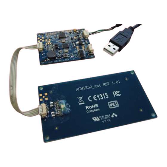
B Cards, MIFARE® cards, FeliCa cards, and all four types of NFC (ISO/IEC 18092 tags). The ACM1252U-Y3, which is the module version of ACR1252U, supports the three modes of NFC, namely: NFC card reader/writer, Card emulation and Peer-to-Peer communication modes. The ACM1252U-Y3 comes with a detachable antenna and an optional USB cable with Molex connector. -
Page 6: Features
Supports Android™ 3.1 and later • Compliant with the following standards: EN 60950/IEC 60950 ISO 14443 ISO 18092 PC/SC CCID RoHS REACH VCCI (Japan) Microsoft® WHQL Uses an ACS-defined Android Library Page 6 of 92 www.acs.com ACM1252U-Y3 – Reference Manual info@acs.com.hk www.acs.com.hk Version 1.03... -
Page 7: Acronyms And Abbreviations
Protocol Parameters Optional information field for Initiator Control information for transaction Maximum value for the Frame Length LLCP Logical Link Control Protocol Table 1: Acronyms and Abbreviations Page 7 of 92 www.acs.com ACM1252U-Y3 – Reference Manual info@acs.com.hk www.acs.com.hk Version 1.03... -
Page 8: Architecture
4.0. Architecture For communication architecture, the protocol used between the ACM1252U-Y3 and the computer is CCID protocol. All communications between PICC and SAM are PC/SC compliant. ACM1252 PCSC ACM1252 PCSC SAM Interface (Optional) PICC Interface Interface (CCID) PCSC Layer ISO 7816 Parts 1-4 T=CL &... -
Page 9: Host Programming (Pc-Linked) Api
= SCardEstablishContext(SCARD_SCOPE_USER, NULL, NULL, &hContext); (retCode != SCARD_S_SUCCESS) // Establishing resource manager context failed else // Establishing resource manager context successful // Further PCSC operation can be performed Page 9 of 92 www.acs.com ACM1252U-Y3 – Reference Manual info@acs.com.hk www.acs.com.hk Version 1.03... -
Page 10: Scardlistreaders
// List the available reader which can be used in the system retCode = SCardListReaders (hContext, NULL, readerName, &size); (retCode != SCARD_S_SUCCESS) // Listing reader fail (readerName == NULL) // No reader available else // Reader listed Page 10 of 92 www.acs.com ACM1252U-Y3 – Reference Manual info@acs.com.hk www.acs.com.hk Version 1.03... -
Page 11: Scardconnect
() … (readerName == NULL) // No reader available else // Reader listed rName = "ACS ACR1252 CL Reader PICC 0"; // Depends on what reader be used // Should connect to PICC interface retCode = SCardConnect(hContext, rName,... -
Page 12: Scardcontrol
SendLen, // APDU command length RecvLen; // APDU response length void main () … rName = "ACS ACR1252 CL Reader PICC 0"; // Depends on what reader will be used // Should connect to PICC interface retCode = SCardConnect(hContext, rName,... - Page 13 SendLen = 6; retCode = SCardControl ( hCard, EscapeCommand, SendBuff, SendLen, RecvBuff, RecvLen, &RecvLen); (retCode != SCARD_S_SUCCESS) // APDU sending failed return; else // APDU sending success Page 13 of 92 www.acs.com ACM1252U-Y3 – Reference Manual info@acs.com.hk www.acs.com.hk Version 1.03...
-
Page 14: Scardtransmit
// APDU command length RecvLen; // APDU response length SCARD_IO_REQUEST ioRequest; void main () … rName = "ACS ACR1252 CL Reader PICC 0"; // Depends on what reader should be used // Should connect to PICC interface retCode = SCardConnect(hContext, rName,... - Page 15 // The RecvBuff stores the IDM for FeliCa / the UID for MIFARE. // Copy the content for further FeliCa access for (int i=0;i< RecvLen-2;i++) CardID [i] = RecvBuff[i]; Page 15 of 92 www.acs.com ACM1252U-Y3 – Reference Manual info@acs.com.hk www.acs.com.hk Version 1.03...
-
Page 16: Scarddisconnect
// Established active protocol retCode; void main () … // Connection successful … retCode = SCardDisconnect(hCard,SCARD_RESET_CARD); (retCode != SCARD_S_SUCCESS) // Disconnection failed else // Disconnection successful Page 16 of 92 www.acs.com ACM1252U-Y3 – Reference Manual info@acs.com.hk www.acs.com.hk Version 1.03... -
Page 17: Apdu Flow
5.1.7. APDU Flow Start SCardEstablishContext SCardListReaders Reader present? SCardConnect Connection successful? SCardTransmit SCardDisconnect Figure 2: ACM1252U-Y3 APDU Flow Page 17 of 92 www.acs.com ACM1252U-Y3 – Reference Manual info@acs.com.hk www.acs.com.hk Version 1.03... -
Page 18: Escape Command Flow
5.1.8. Escape Command Flow Start SCardEstablishContext SCardListReaders Reader present? SCardConnect SCardControl SCardDisconnect Figure 3: ACM1252U-Y3 Escape Command Flow Page 18 of 92 www.acs.com ACM1252U-Y3 – Reference Manual info@acs.com.hk www.acs.com.hk Version 1.03... -
Page 19: Contactless Smart Card Protocol
Standard (SS) (ISO 14443A, Part 3) Card Name (C0 .. C1) = {00 01h} (MIFARE Classic 1K) Standard (SS) = 03h: ISO 14443A, Part 3 = 11h: FeliCa Page 19 of 92 www.acs.com ACM1252U-Y3 – Reference Manual info@acs.com.hk www.acs.com.hk Version 1.03... - Page 20 3 + N Application Protocol Info Higher Data from Byte from nibble=MBLI ATQB ATQB from ATTRIB command Lower nibble (RFU)=0 Exclusive-oring of all the bytes T0 to Tk Page 20 of 92 www.acs.com ACM1252U-Y3 – Reference Manual info@acs.com.hk www.acs.com.hk Version 1.03...
- Page 21 1C 2D 94 11 F7 71 85 00 BEh} Application Data of ATQB = 1C 2D 94 11h Protocol Information of ATQB = F7 71 85h MBLI of ATTRIB = Page 21 of 92 www.acs.com ACM1252U-Y3 – Reference Manual info@acs.com.hk www.acs.com.hk Version 1.03...
-
Page 22: Pseudo Apdu For Contactless Interface
UINT8 GET_UID[5] = {FF, CA, 00, 00, 00}; To get the ATS of the “connected ISO 14443 A PICC”: UINT8 GET_ATS[5] = {FF, CA, 01, 00, 00}; Page 22 of 92 www.acs.com ACM1252U-Y3 – Reference Manual info@acs.com.hk www.acs.com.hk Version 1.03... -
Page 23: Apdu Commands For Pcsc 2.0 Part 3 (Version 2.02 Or Above)
XX 63 01h Execution stopped due to failure in other data object XX 6A 81h Data object XX not supported XX 67 00h Data object XX with unexpected length Page 23 of 92 www.acs.com ACM1252U-Y3 – Reference Manual info@acs.com.hk www.acs.com.hk Version 1.03... - Page 24 FF 6Dh Get Parameter FF 6Eh Set Parameter Manage Session Response Data Object Data Object Generic Error status Version data object FF 6Dh IFD parameter data object Page 24 of 92 www.acs.com ACM1252U-Y3 – Reference Manual info@acs.com.hk www.acs.com.hk Version 1.03...
- Page 25 5.2.3.2.5. Turn On the RF Data Object This command is used to turn on the antenna field. Turn on the RF Field Data Object Length (1 byte) Value Page 25 of 92 www.acs.com ACM1252U-Y3 – Reference Manual info@acs.com.hk www.acs.com.hk Version 1.03...
- Page 26 5.2.3.2.8. Set Parameter Data Object This command is used to set different parameters from the IFD. Set Parameter Data Object Value Length (1 byte) Value FF 6Eh TLV_Objects Page 26 of 92 www.acs.com ACM1252U-Y3 – Reference Manual info@acs.com.hk www.acs.com.hk Version 1.03...
- Page 27 FF 6Eh Set Parameter Transparent Exchange Response Data Object Data Object Generic Error status Number of valid bits in the last byte of received data Response Status Page 27 of 92 www.acs.com ACM1252U-Y3 – Reference Manual info@acs.com.hk www.acs.com.hk Version 1.03...
- Page 28 Transmission bit framing data object shall be together with “transmit” or “transceive” data object only. If this data object does not exist, it means all bits are valid. Page 28 of 92 www.acs.com ACM1252U-Y3 – Reference Manual info@acs.com.hk www.acs.com.hk Version 1.03...
- Page 29 Set Parameter FWTI Data Object. If no FWTI is set, the reader will wait for about 302 µs. Transceive Data Object Length (1 byte) Value DataLen Data (N Bytes) Page 29 of 92 www.acs.com ACM1252U-Y3 – Reference Manual info@acs.com.hk www.acs.com.hk Version 1.03...
- Page 30 Class Data In DataObject SwProtocol DataLen (N bytes) Where: Data Object (1 byte) Data Object Switch Protocol Data Object FF 6Dh Get Parameter FF 6Eh Set Parameter Page 30 of 92 www.acs.com ACM1252U-Y3 – Reference Manual info@acs.com.hk www.acs.com.hk Version 1.03...
- Page 31 Response: C0 03 00 90 00 90 00 2. Turn the Antenna Field on. Command: FF C2 00 00 02 84 00 Response: C0 03 00 90 00 90 00 Page 31 of 92 www.acs.com ACM1252U-Y3 – Reference Manual info@acs.com.hk www.acs.com.hk Version 1.03...
- Page 32 4. Set the PCB to 0Ah and enable the CRC, parity and protocol prologue in the transmit data. Command: FF C2 00 01 0A 90 02 00 00 FF 6E 03 07 01 0A Response: C0 03 00 90 00 90 00 Page 32 of 92 www.acs.com ACM1252U-Y3 – Reference Manual info@acs.com.hk www.acs.com.hk Version 1.03...
- Page 33 Response: C0 03 00 90 00 92 01 00 96 02 00 00 97 0C [Card Response] 90 00 6. End Transparent Session. Command: FF C2 00 00 02 82 00 Response: C0 03 00 90 00 90 00 Page 33 of 92 www.acs.com ACM1252U-Y3 – Reference Manual info@acs.com.hk www.acs.com.hk Version 1.03...
-
Page 34: Picc Commands For Mifare® Classic (1K/4K) Memory Cards
// Load a key {FF FF FF FF FF FFh} into the volatile memory location 00h. APDU = {FF 82 00 00 06 FF FF FF FF FF FFh} Page 34 of 92 www.acs.com ACM1252U-Y3 – Reference Manual info@acs.com.hk www.acs.com.hk Version 1.03... - Page 35 PC. Two volatile keys are provided. The volatile key can be used as a session key for different sessions. Load Authentication Keys Response Format (2 bytes) Response Data Out Result Page 35 of 92 www.acs.com ACM1252U-Y3 – Reference Manual info@acs.com.hk www.acs.com.hk Version 1.03...
-
Page 36: Table 2: Mifare® Classic 1K Memory Map
80h ~ 8Eh Sector 33 90h ~ 9Eh 2 KB Sector 38 E0h ~ EEh Sector 39 F0h ~ FEh Table 3: MIFARE® Classic 4K Memory Map Page 36 of 92 www.acs.com ACM1252U-Y3 – Reference Manual info@acs.com.hk www.acs.com.hk Version 1.03... -
Page 37: Table 4: Mifare® Ultralight® Memory Map
APDU = {FF 86 00 00 05 01 00 60 00h} Note: MIFARE Ultralight does not need to do any authentication. The memory is free to access. Page 37 of 92 www.acs.com ACM1252U-Y3 – Reference Manual info@acs.com.hk www.acs.com.hk Version 1.03... - Page 38 APDU = FF B0 00 // Read 240 bytes starting from the binary block (MIFARE Classic 4K) // Block 80h to Block 8Eh (15 blocks) APDU = FF B0 00 Page 38 of 92 www.acs.com ACM1252U-Y3 – Reference Manual info@acs.com.hk www.acs.com.hk Version 1.03...
- Page 39 10 00 01 02 03 04 05 06 07 08 09 0A 0B 0C 0D 0E 0Fh} // Update the binary block of MIFARE Ultralight with Data {00 01 02 03h} APDU = {FF D6 00 04 00 01 02 03h} Page 39 of 92 www.acs.com ACM1252U-Y3 – Reference Manual info@acs.com.hk www.acs.com.hk Version 1.03...
- Page 40 Value Block Operation Response Format (2 bytes) Response Data Out Result Value Block Operation Response Codes Results Meaning The operation was completed Success successfully. Error The operation failed. Page 40 of 92 www.acs.com ACM1252U-Y3 – Reference Manual info@acs.com.hk www.acs.com.hk Version 1.03...
- Page 41 Example 2: Decimal 1 = {00h, 00h, 00h, 01h} Value Read Value Block Response Codes Results Meaning The operation was completed Success successfully. Error The operation failed. Page 41 of 92 www.acs.com ACM1252U-Y3 – Reference Manual info@acs.com.hk www.acs.com.hk Version 1.03...
- Page 42 // Copy the value from value block to value block APDU = {FF D7 06h} by “5” // Increment the value block APDU = {FF D7 00 00 00 05h} Page 42 of 92 www.acs.com ACM1252U-Y3 – Reference Manual info@acs.com.hk www.acs.com.hk Version 1.03...
-
Page 43: Accessing Pcsc-Compliant Tags (Iso 14443-4)
All ISO 14443-4 compliant cards (PICCs) understand the ISO 7816-4 APDUs. The ACM1252U-Y3 reader just has to communicate with the ISO 14443-4 compliant cards through exchanging ISO 7816- 4 APDUs and responses. The ACM1252U-Y3 will handle the ISO 14443 Parts 1-4 Protocols internally. - Page 44 INS = B2h P1 = 80h P2 = 00h Lc = None Data In = None Le = 08h Answer: 00 01 02 03 04 05 06 07h [$9000h] Page 44 of 92 www.acs.com ACM1252U-Y3 – Reference Manual info@acs.com.hk www.acs.com.hk Version 1.03...
-
Page 45: Accessing Felica Tags
01 01 06 01 CB 09 57 03 01 09 01 01 80 00h IDM = 01 01 06 01 CB 09 57 03h RES = Memory Block Data Page 45 of 92 www.acs.com ACM1252U-Y3 – Reference Manual info@acs.com.hk www.acs.com.hk Version 1.03... -
Page 46: Peripherals Control
Response = E1 00 00 00 0F 41 43 52 31 32 35 32 55 5F 56 32 30 32 2E 32 Firmware Version (HEX) = 41 43 52 31 32 35 32 55 5F 56 32 30 32 2E 32 Firmware Version (ASCII) = “ACR1252U_V202.2” Page 46 of 92 www.acs.com ACM1252U-Y3 – Reference Manual info@acs.com.hk www.acs.com.hk Version 1.03... -
Page 47: Led Control
LED Status Description Description Bit 0 RED LED 1 = ON; 0 = OFF Bit 1 GREEN LED 1 = ON; 0 = OFF Bit 2 - 7 Page 47 of 92 www.acs.com ACM1252U-Y3 – Reference Manual info@acs.com.hk www.acs.com.hk Version 1.03... -
Page 48: Led Status
LED Status Description Description Bit 0 RED LED 1 = ON; 0 = OFF Bit 1 GREEN LED 1 = ON; 0 = OFF Bit 2 - 7 Page 48 of 92 www.acs.com ACM1252U-Y3 – Reference Manual info@acs.com.hk www.acs.com.hk Version 1.03... -
Page 49: Buzzer Control
Buzzer On Duration 1 byte. 00h = Turn OFF 01 to FFh = Duration (unit: 10 ms) Buzzer Control Response Format (6 bytes) Response Class Data Out Result Page 49 of 92 www.acs.com ACM1252U-Y3 – Reference Manual info@acs.com.hk www.acs.com.hk Version 1.03... -
Page 50: Buzzer Status
This command is used to check the existing buzzer status. Buzzer Status Format (5 bytes) Command Class Buzzer Status Buzzer Status Response Format (6 bytes) Response Class Data Out Result Page 50 of 92 www.acs.com ACM1252U-Y3 – Reference Manual info@acs.com.hk www.acs.com.hk Version 1.03... -
Page 51: Set Led And Buzzer Status Indicator Behavior For Picc Interface
Note: Default value of Behavior = 7Fh Set LED and Buzzer Status Indicator Behaviors for PICC Interface Response Format (6 bytes) Response Class Data Out Result Default Behaviors Page 51 of 92 www.acs.com ACM1252U-Y3 – Reference Manual info@acs.com.hk www.acs.com.hk Version 1.03... -
Page 52: Read Led And Buzzer Status Indicator Behavior For Picc Interface
1 = Enable; 0 = Disable RED LED for status change Bit 7 Color Select (RED) 1 = Enable; 0 = Disable Note: Default value of Behavior = 7Fh Page 52 of 92 www.acs.com ACM1252U-Y3 – Reference Manual info@acs.com.hk www.acs.com.hk Version 1.03... -
Page 53: Set Automatic Picc Polling
<1 – 1> = 2500 ms Bit 6 Bit 7 Enforce ISO 14443-A Part 4 1= Enable; 0= Disable. Note: Default value of Polling Setting = 8Bh. Page 53 of 92 www.acs.com ACM1252U-Y3 – Reference Manual info@acs.com.hk www.acs.com.hk Version 1.03... - Page 54 4. The JCOP30 card comes with two modes: ISO 14443A-3 (MIFARE Classic 1K) and ISO 14443A-4 modes. The application has to decide which mode should be selected once the PICC is activated. Page 54 of 92 www.acs.com ACM1252U-Y3 – Reference Manual info@acs.com.hk www.acs.com.hk Version 1.03...
-
Page 55: Read Automatic Picc Polling
<1 – 1> = 2500 ms Bit 6 Bit 7 Enforce ISO 14443-A Part 4 1= Enable; 0= Disable. Note: Default value of Polling Setting = 8Bh. Page 55 of 92 www.acs.com ACM1252U-Y3 – Reference Manual info@acs.com.hk www.acs.com.hk Version 1.03... -
Page 56: Set Picc Operating Parameter
FeliCa 424 Kbps 0 = Skip 1 = Detect Bit 4 Topaz 0 = Skip Bit 5 - 7 Note: Default value of Operation Parameter = 1Fh. Page 56 of 92 www.acs.com ACM1252U-Y3 – Reference Manual info@acs.com.hk www.acs.com.hk Version 1.03... -
Page 57: Read Picc Operating Parameter
FeliCa 424 Kbps 0 = Skip 1 = Detect Bit 4 Topaz 0 = Skip Bit 5 - 7 Note: Default value of Operation Parameter = 1Fh. Page 57 of 92 www.acs.com ACM1252U-Y3 – Reference Manual info@acs.com.hk www.acs.com.hk Version 1.03... -
Page 58: Set Auto Pps
PICC. The PICC will become inaccessible is the PICC or environment does not meet the requirement of the proposed communication speed. 2. The reader supports different speed between sending and receiving. Page 58 of 92 www.acs.com ACM1252U-Y3 – Reference Manual info@acs.com.hk www.acs.com.hk Version 1.03... -
Page 59: Read Auto Pps
Current Rx Speed Current Rx Speed (1 Byte) 00h = 106 Kbps; default setting, equal to No Auto PPS 01h = 212 Kbps 02h = 424 Kbps Page 59 of 92 www.acs.com ACM1252U-Y3 – Reference Manual info@acs.com.hk www.acs.com.hk Version 1.03... -
Page 60: Read Serial Number
Read the Serial Number Format (5 bytes) Command Class Read the Serial Number Read the Serial Number Response Format Response Class Data Out Serial Number Result (N bytes) Page 60 of 92 www.acs.com ACM1252U-Y3 – Reference Manual info@acs.com.hk www.acs.com.hk Version 1.03... -
Page 61: Nfc Peer-To-Peer Mode-Related Commands
This section provides the commands that can be used in Initiator Mode. The figure below shows the peer-to-peer flow of commands for Initiator Mode. Figure 4: Peer-to-Peer Flow for Initiator Mode Page 61 of 92 www.acs.com ACM1252U-Y3 – Reference Manual info@acs.com.hk www.acs.com.hk Version 1.03... - Page 62 Set Initiator Mode Timeout Response Format (7 bytes) Response Class Data Out Timeout Timeout Result (MSB) (LSB) Where: Timeout 2 bytes. Timeout for Initiator Mode (unit = 10 ms). Page 62 of 92 www.acs.com ACM1252U-Y3 – Reference Manual info@acs.com.hk www.acs.com.hk Version 1.03...
- Page 63 Target Mode, will present and send out the pre-set SNEP Message to it. The reader will stop all other tasks until the SNEP Message is sent successfully. Page 63 of 92 www.acs.com ACM1252U-Y3 – Reference Manual info@acs.com.hk www.acs.com.hk Version 1.03...
- Page 64 1 byte. Initiator device’s Device Identification. 1 byte. Initiator device’s support send-bit rates. 1 byte. Initiator device’s support bit rates. 1 byte. Initiator device’s optional parameters. N bytes. LLCP parameter. Page 64 of 92 www.acs.com ACM1252U-Y3 – Reference Manual info@acs.com.hk www.acs.com.hk Version 1.03...
- Page 65 Dep Response (Len bytes) Where: 1 byte. Control the data transmission and error recovery. DepLen 1 byte. DEP message length. N bytes. DEP message for peer-to-peer communication. Page 65 of 92 www.acs.com ACM1252U-Y3 – Reference Manual info@acs.com.hk www.acs.com.hk Version 1.03...
- Page 66 Data Out Result Return Code (2 bytes) Return Code Results SW1 SW2 Meaning The operation was completed Success 90 00h successfully. Error 63 00h The operation failed. Page 66 of 92 www.acs.com ACM1252U-Y3 – Reference Manual info@acs.com.hk www.acs.com.hk Version 1.03...
- Page 67 Data Out Result Return Code (2 bytes) Return Code Results SW1 SW2 Meaning The operation was completed Success 90 00h successfully. Error 63 00h The operation failed. Page 67 of 92 www.acs.com ACM1252U-Y3 – Reference Manual info@acs.com.hk www.acs.com.hk Version 1.03...
-
Page 68: Target Mode-Related Commands
This section provides the commands that can be used when in Target Mode. The figure below shows the peer-to-peer flow of commands for Target Mode. Figure 5: Peer-to-Peer Flow for Target Mode Page 68 of 92 www.acs.com ACM1252U-Y3 – Reference Manual info@acs.com.hk www.acs.com.hk Version 1.03... - Page 69 Note: Unit = 100 µs, default value of Target Timeout = 00 C8h (200 * 100 µs = 20 ms). Set Target Timeout Response Format Response Class Data Out Timeout Timeout Result (MSB) (LSB) Where: Timeout 2 bytes. Timeout for Target Mode (unit =100 µs). Page 69 of 92 www.acs.com ACM1252U-Y3 – Reference Manual info@acs.com.hk www.acs.com.hk Version 1.03...
- Page 70 After executing Enter Target Mode, the reader will wait for the NFC device, which in Initiator Mode, will present and receive the SNEP message. The reader will stop all other tasks until the SNEP Message is exchanged successfully. Page 70 of 92 www.acs.com ACM1252U-Y3 – Reference Manual info@acs.com.hk www.acs.com.hk Version 1.03...
- Page 71 Data Out Return Code Result (2 bytes) Return Code Results SW1 SW2 Meaning The operation was completed Success 90 00h successfully. Error 63 00h The operation failed. Page 71 of 92 www.acs.com ACM1252U-Y3 – Reference Manual info@acs.com.hk www.acs.com.hk Version 1.03...
- Page 72 Data Out Return Code Result (2 bytes) Return Code Results SW1 SW2 Meaning The operation was completed Success 90 00h successfully. Error 63 00h The operation failed. Page 72 of 92 www.acs.com ACM1252U-Y3 – Reference Manual info@acs.com.hk www.acs.com.hk Version 1.03...
- Page 73 Data Out Return Code Result (2 bytes) Return Code Results SW1 SW2 Meaning The operation was completed Success 90 00h successfully. Error 63 00h The operation failed. Page 73 of 92 www.acs.com ACM1252U-Y3 – Reference Manual info@acs.com.hk www.acs.com.hk Version 1.03...
- Page 74 Data Out Return Code Result (2 bytes) Return Code Results SW1 SW2 Meaning The operation was completed Success 90 00h successfully. Error 63 00h The operation failed. Page 74 of 92 www.acs.com ACM1252U-Y3 – Reference Manual info@acs.com.hk www.acs.com.hk Version 1.03...
- Page 75 Data Out Result Return Code (2 bytes) Return Code Results SW1 SW2 Meaning The operation was completed Success 90 00h successfully. Error 63 00h The operation failed. Page 75 of 92 www.acs.com ACM1252U-Y3 – Reference Manual info@acs.com.hk www.acs.com.hk Version 1.03...
- Page 76 Data Out Result Return Code (2 bytes) Return Code Results SW1 SW2 Meaning The operation was completed Success 90 00h successfully. Error 63 00h The operation failed. Page 76 of 92 www.acs.com ACM1252U-Y3 – Reference Manual info@acs.com.hk www.acs.com.hk Version 1.03...
- Page 77 Data Out Result SNEP Message Len SNEP Message Where: SNEP Message Len 1 byte. Length of the received SNEP Message. SNEP Message Received SNEP message from Initiator devices. Page 77 of 92 www.acs.com ACM1252U-Y3 – Reference Manual info@acs.com.hk www.acs.com.hk Version 1.03...
-
Page 78: Nfc Card Emulation Mode-Related Commands
1 byte. NFC Device Mode. 01h = MIFARE Ultralight Card Emulation Mode 03h = FeliCa Card Emulation Mode 06h = Peer-to-Peer Initiator Mode Other = Card Read/Write Mode Page 78 of 92 www.acs.com ACM1252U-Y3 – Reference Manual info@acs.com.hk www.acs.com.hk Version 1.03... -
Page 79: Table 5: Mifare® Ultralight® Memory Map (52 Bytes)
48-51 Table 5: MIFARE® Ultralight® Memory Map (52 bytes) Where: Default SN[0-6] {04h, 96h, 50h, 01h, F4h, 02h, 80h} Default Data[0-3] {E1h, 10h, 06h, 00h} //NFC Type2Tag Page 79 of 92 www.acs.com ACM1252U-Y3 – Reference Manual info@acs.com.hk www.acs.com.hk Version 1.03... -
Page 80: Table 6: Felica Memory Map (160 Bytes)
1. FeliCa card emulation supports Read/Write without Encryption 2. The FeliCa Card Identification Number in IDm is user programmable, but the Manufacturer Code is fixed at (03 88). Page 80 of 92 www.acs.com ACM1252U-Y3 – Reference Manual info@acs.com.hk www.acs.com.hk Version 1.03... -
Page 81: Read Card Emulation Data (Mifare® Ultralight® Or Felica)
03h = FeliCa Card Emulation Mode StartOffset 1 byte. Address start to read. Length 1 byte. Number of byte going to read. Data being read The output data. Page 81 of 92 www.acs.com ACM1252U-Y3 – Reference Manual info@acs.com.hk www.acs.com.hk Version 1.03... -
Page 82: Write Card Emulation Data (Mifare® Ultralight® Or Felica)
03h = FeliCa Card Emulation Mode StartOffset 1 byte. Address start to read. Length 1 byte. Number of bytes to write. Data to Write The binary data to write. Page 82 of 92 www.acs.com ACM1252U-Y3 – Reference Manual info@acs.com.hk www.acs.com.hk Version 1.03... -
Page 83: Set Card Emulation Of Mifare® Ultralight® Uid
Set Card Emulation Ultralight UID 7 bytes UID Set Card Emulation MIFARE Ultralight UID Response Format (7 bytes) Response Class Data Out Result Where: 7 bytes. 7 bytes MIFARE UID. Page 83 of 92 www.acs.com ACM1252U-Y3 – Reference Manual info@acs.com.hk www.acs.com.hk Version 1.03... -
Page 84: Set Card Emulation Felica Idm
Class Data In Set Card Emulation Felica IDm Set Card Emulation FeliCa Card Identification number Response Format (11 bytes) Response Class Data Out Result Where: 6 bytes. Page 84 of 92 www.acs.com ACM1252U-Y3 – Reference Manual info@acs.com.hk www.acs.com.hk Version 1.03... -
Page 85: Set Card Emulation Lock Data In Nfc
Data cannot be modified via NFC. 1: Lock enable The data can still be modified by 0: Lock disable MIFARE Ultralight using the USB escape command. Lock Enable 1: Lock enable Page 85 of 92 www.acs.com ACM1252U-Y3 – Reference Manual info@acs.com.hk www.acs.com.hk Version 1.03... -
Page 86: Acr122U Compatible Commands
01h = The buzzer will turn on during the T1 Duration. 02h = The buzzer will turn on during the T2 Duration. 03h = The buzzer will turn on during the T1 and T2 Duration. Page 86 of 92 www.acs.com ACM1252U-Y3 – Reference Manual info@acs.com.hk www.acs.com.hk Version 1.03... - Page 87 6. To make the buzzer operate, the “number of repetitions” must greater than zero. 7. To control the LED only, just set the parameter “Link to Buzzer” to zero. Page 87 of 92 www.acs.com ACM1252U-Y3 – Reference Manual info@acs.com.hk www.acs.com.hk Version 1.03...
-
Page 88: Get Firmware Version
Response Data Out Result Firmware Version Example: Response = 41 43 52 31 32 35 32 55 5F 56 32 30 32 2E 32h = ACR1252U_V202.2 (ASCII) Page 88 of 92 www.acs.com ACM1252U-Y3 – Reference Manual info@acs.com.hk www.acs.com.hk Version 1.03... -
Page 89: Get The Picc Operating Parameter
ISO14443 Type B 0 = Skip ISO14443 Type A Note: To detect the 1 = Detect MIFARE Tags, the Auto 0 = Skip ATS Generation must be disabled first. Page 89 of 92 www.acs.com ACM1252U-Y3 – Reference Manual info@acs.com.hk www.acs.com.hk Version 1.03... -
Page 90: Set The Picc Operating Parameter
ISO14443 Type B 0 = Skip ISO14443 Type A Note: To detect the 1 = Detect MIFARE tags, the Auto 0 = Skip ATS Generation must be disabled first. Page 90 of 92 www.acs.com ACM1252U-Y3 – Reference Manual info@acs.com.hk www.acs.com.hk Version 1.03... -
Page 91: Appendix A. Snep Message
The length of the URI payload (11 bytes) Record type: “U” 55 (“U”) Abbreviation: “http://www.” 61 63 73 2E 63 6F The URL itself. “acs.com.hk” 6D 2E 68 6B Page 91 of 92 www.acs.com ACM1252U-Y3 – Reference Manual info@acs.com.hk www.acs.com.hk Version 1.03... -
Page 92: Appendix B. Escape Command Example
Microsoft is a registered trademark of Microsoft Corporation in the United States and/or other countries. MIFARE, MIFARE Classic, MIFARE DESFire and MIFARE Ultralight are registered trademarks of NXP B.V. Page 92 of 92 www.acs.com ACM1252U-Y3 – Reference Manual info@acs.com.hk www.acs.com.hk Version 1.03...
Need help?
Do you have a question about the ACM1252U-Y3 and is the answer not in the manual?
Questions and answers