
Related Manuals for ACS TCO-U


Summary of Contents for ACS TCO-U
- Page 1 Upright Hot Oil Temperature Control Units Models Covered: TCO-U; 2016U Part Number: 882.12044.00 Bulletin Number: WTR2-640 Effective: August 1, 2012...
- Page 2 Write Down Your Serial Numbers Here For Future Reference: _________________________ _________________________ _________________________ _________________________ _________________________ _________________________ We are committed to a continuing program of product improvement. Specifications, appearance, and dimensions described in this manual are subject to change without notice. DCN No. ____________ ©...
- Page 3 Shipping Info Unpacking and Inspection You should inspect your granulator for possible shipping damage. Thoroughly check the equipment for any damage that might have occurred in transit, such as broken or loose wiring and components, loose hardware and mounting screws, etc. In the Event of Shipping Damage According to the contract terms and conditions of the Carrier, the responsibility of the Shipper ends at the time and place of shipment.
- Page 4 Returns Do not return any damaged or incorrect items until you receive shipping instructions from the shipping department. Credit Returns Prior to the return of any material, authorization must be given by the manufacturer. A RMA number will be assigned for the equipment to be returned. Reason for requesting the return must be given.
-
Page 5: Table Of Contents
Table of Contents CHAPTER 1: SAFETY ..............5 How to Use This Manual ....................5 Safety Symbols Used in this Manual ..............5 General Safety Regulations ..................7 Responsibility ....................... 7 ... - Page 6 Controller Description & Operation ................21 Identifying Control Panel Switches…………………………………………………..21 Identifying System Status Board Indicators…………………………………………22 Status Indicator Lights………………………………………………………………...23 Mode Indicator Lights……………………………………........24 Fault Indicator Lights…………………………………………………………………..24 Returning Fluid to the Tank………………………………………………………………...25 4-‐4 Shutting Down the Hot Oil TCU .................. 26 CHAPTER 5: MAINTENANCE ..........
-
Page 7: Chapter 1: Safety
Chapter 1: Safety How to Use This Manual Use this manual as a guide and reference for installing, operating, and maintaining your granulator. The purpose is to assist you in applying efficient, proven techniques that enhance equipment productivity. This manual covers only light corrective maintenance. No other maintenance should be undertaken without first contacting a service engineer. - Page 8 Safety Tags and warning features Hazard Alert Description/Explanation Preventative Maintenance Symbol High Voltage Hazard. The electrical Every six months inspect all electrical enclosure is supplied with 3-phase electrical connections for secure attachment. For power. Use caution when using or further information see the maintaining this product.
-
Page 9: Warnings And Precautions
Warnings and Precautions Our units are designed to provide safe and reliable operation when installed and operated within design specifications, following national and local safety codes. To avoid possible personal injury or equipment damage when installing, operating, or maintaining this unit, use good judgment and follow these safe practices: þ... -
Page 10: Chapter 2: Functional Description
Chapter 2: Functional Description Models Covered in This Manual This manual provides operation, installation, and maintenance instructions for portable hot oil temperature control units. Model numbers are listed on the serial tag. Make sure you know the model and serial number of your equipment before contacting the manufacturer for parts or service. -
Page 11: Electrical Features
Electrical Features Non-fused lockable rotary disconnect • Branch circuit fusing • NEMA 12 electrical enclosure • UL listed subpanel • Options Drain valve • Hour meter; measures total pump run time hours • General fault visual alarm • Autovent sequence; deducts available •... -
Page 12: Pump
Pump The pump is a mechanical seal, positive displacement pump. It features a nearly maintenance free design, and was selected after extensive testing to provide superior performance, flexibility, and low maintenance. It is well suited for use with a variety of commercially available heat transfer fluids. -
Page 13: Electrical Panel And System Components
An audible alarm is standard with your unit. The alarm will sound in the event of the following conditions: Motor overload • Safety thermostat trip (over temperature) • Low fluid pressure • Low fluid level • High fluid level (optional) •... -
Page 14: Reservoir Tank
imperative that a qualified maintenance technician determine and correct the cause of the fault before resuming operation. Reservoir Tank A reservoir tank with sight gauge is standard; usable capacity is seven (7) gallons (26.5 liters). The tank permits thermal expansion of the heat transfer fluid, and provides makeup fluid. The reservoir tank may cause serious injury if it ruptures from not being properly vented. -
Page 15: Fail Safe Operation
Fail Safe Operation If a safety device or circuit should fail, the design must be such that the failure causes a “Safe” condition. As an example, a safety switch must be a normally open switch. The switch must be held closed with the device it is to protect. If the switch fails, it will go to the open condition, tripping out the safety circuit. -
Page 16: Chapter 3: Installation
Chapter 3: Installation Uncrating the Equipment Portable hot oil temperature control units are shipped mounted on a skid, enclosed in a plastic wrapper, and contained in a cardboard box. 1. Pry the crating away from the skid. Remove the nails holding the box to the skid and lift the box off carefully; avoiding staples in the 1’... -
Page 17: Electrical Connections
Electrical Connections These units are designed for three-phase voltage operation. Refer to the unit nameplate for proper voltage and amperage requirements, and make sure your electrical service conforms. Check the unit nameplate for correct voltage and amperage before making electrical connections! 1. -
Page 18: Connecting Process Piping
The following table lists recommended Upright TCU pipe sizes. Size diameter Connection inches NPT mm (approx.) c To Process 1” 25.4 From Process 1” 25.4 Cooling Water Supply ¾” 19.1 Cooling Water Drain ¾” 19.1 Oil Drain ½” 12.7 Fill Port 1”... - Page 19 Connecting Cooling Water Piping You must provide cooling water at 25 psi to 75 psi (172.4 kPa to 517.1 kPa/1.7 bars to 5.2 bars) for proper operation. Untreated water can foul or corrode the heat transfer surfaces, slowing water flow and causing fluid temperature control problems. The manufacturer sells a complete line of water treatment equipment that can reduce downtime and maintenance costs.
-
Page 20: Initial Start-Up
Connect the TO PROCESS hookup to the entrance of the process and the FROM PROCESS hookup to the exit of the process. Connect the COOLING WATER SUPPLY to your plant water supply. Connect the COOLING WATER DRAIN line to an open drain, or to the return line of your central water system. - Page 21 7. Any water present in the system must boil off before continuing operation. Select a set point of 215ºF (102ºC) and observe the reservoir tank vent for any signs of escaping steam. Continue to run at this set point temperature until no more steam appears and pressure stabilizes.
-
Page 22: Chapter 4: Operation
Chapter 4: Operation Start-up 1. Push the PUMP START button to start the pump. 2. When the unit has built at least five (5) psi (34.5 kPa) of pressure, wait two (2) minutes, then select a set point of 100°F (38ºC) and switch the unit into AUTO mode. -
Page 23: Identifying Control Panel Switches
Identifying Control Panel Switches This section lists the descriptions and functions of the control panel switches. These switches control the operation of the unit. Pump Start. Press the START button to start the pump in the normal forward direction. Pump Stop. Press the STOP button to stop the pump and de-energize the controller. Always press the Pump Stop button and allow the pump to come to a complete stop before pressing the Pump Reverse button. -
Page 24: Status Indicator Lights
Figure 5: System Status Board Indicators Use the status board to optimize unit performance. For example, if you observe a rapid cycling of the Heater and Cool Solenoid indicators, the unit is operating with a process inefficiency; see the Troubleshooting section for more information. What follows is a description of system status board indicators. -
Page 25: Mode Indicator Lights
Mode Indicator Lights Select the unit operating mode by using the selection switch. Power On Mode Indicator Light. The Power On mode indicator light illuminates to indicate that the control circuit is energized in the unit. Auto Mode Indicator Light. The Auto mode indicator light indicates that the Auto mode is active and the controller is monitoring the system and controlling the process. -
Page 26: Returning Fluid To The Tank
Returning Fluid to the Tank If you want to move the unit from one process to another (like mold changes), perform the following steps to drain the mold and process lines. This procedure is just the opposite of the unit startup/air purge procedure. 1. -
Page 27: Chapter 5: Maintenance
Chapter 5: Maintenance Maintenance Schedule The checklist below contains a list of items which should be inspected and/or replaced to keep your Portable Hot Oil TCU operating at peak efficiency. Perform each inspection at the regular intervals listed below. System model # Serial # Date/ Date/... -
Page 28: Preventative Maintenance
Preventative Maintenance Make sure that your maintenance technicians comply with lock-out/tag-out procedures during any servicing or maintenance of this unit and related equipment, per OSHA article ART 1910.147. Before you begin servicing this unit, disconnect all power to it, let the unit cool down completely, and turn off the water. -
Page 29: Corrective Maintenance
Adjusting End Clearance After long periods of service, the running clearance between the end of the rotor teeth and head may be increased from wear. The pump may lose some capacity of pressure as a result. If you reset the end clearance, pump performance should improve. Examining Internal Parts Remove the head occasionally and examine the idler, bushing, head and pin for wear. -
Page 30: Maintaining The Pump
Maintaining the Pump Disassembling the Pump Before opening the pump chamber: • Make sure that any pressure in the chamber has been completely vented! • Make sure that the motor cannot be inadvertently started while you work on the pump! Failure to follow these precautions may result in serious injury or death! Mark the head and casing before disassembly to insure proper reassembly. - Page 31 Pump Assembly The seal used in this pump is simple to install. If you take care during installation, good performance will result. The principle of the mechanical seal is to make contact between the rotary and stationary members. These parts are lapped to a high finish, and their sealing effectiveness depends on complete contact.
-
Page 32: Thrust Bearing Adjustment
Thrust Bearing Adjustment 1. Loosen axial setscrews in face of end cap on the thrust bearing assembly. If rotor shaft cannot be turned by hand, back off the thrust bearing assembly until there is a noticeable drag of the shaft. Note mechanical seal will provide some drag and this is a normal condition. -
Page 33: Chapter 6: Troubleshooting
Chapter 6: Troubleshooting Introduction The utmost in safety precautions should be observed at all times when working on or around the machine and the electrical components. All normal trouble-shooting must be accomplished with the power off, line fuses removed, and with the machine tagged as out of service. - Page 34 Problem Possible cause Corrective action Check all lines/connections/ Loss of fluid in process. fittings. Allow vent timer to run out; or, Vent valve open. check valve operation when unit is cold by opening the fill port. Unit does not heat properly/can Switch to Manual Cool mode not achieve set point.
- Page 35 Problem Possible cause Corrective action Inspect/replace faulty line or Leaks in connecting lines. connection. Perform venting sequence in Air in circulating lines. Chapter 3. Check fluid level in sight glass. Low fluid. Add fluid if required. Defective Ful-Flo valve. See Chapter 3. Drain water from low point in Water in fluid.
-
Page 36: Chapter 7: Appendix
Chapter 7: Appendix Technical Specifications The following design information is provided for your reference: 1. No modifications are allowed to this equipment that could alter the CE compliance 2. Ambient temperature: 40 degrees Celsius – Maximum (104 degrees Fahrenheit) 3. Humidity range: 50% relative humidity 4. - Page 37 27. The machine is not equipped with cableless controls. 28. Color-coded (harmonized) power cord is sufficient for proper installation. WTR2-640 Chapter 7: Appendix 37 of 46...
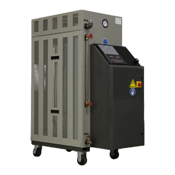
- Page 38 Figure 6: Upright Series Hot Oil Portable Temperature Control Unit Upright Series Temperature Control Unit Specifications Model number Upright- Full load amps; 460/3/60 VAC 12 kW heater 18 kW heater 24 kW heater 36 kW heater 48 kW heater Reservoir capacity in gallons / liters 17 gallons each zone c TEFC pump hp (kW)
- Page 39 Drawings and Diagrams Figure 7: 18-24 GPM Pump Construction 075-00370-02 WTR2-640 Chapter 7: Appendix 39 of 46...
- Page 40 Figure 8: Thrust Bearing Assembly Figure 9: Belt Tensioning Instructions WTR2-640 Chapter 7: Appendix 40 of 46...
- Page 41 WTR2-640 Chapter 7: Appendix 41 of 46...
- Page 42 Spare Parts List Immersion Heaters Part number Description 722-00138-07 HTR, IMM, 12 KW, 208 V, 3”, 6 ELE 722-00138-08 HTR, IMM, 12 KW, 240 V, 3”, 6 ELE 722-00138-09 HTR, IMM, 12 KW, 380 V, 3”, 6 ELE 722-00138-10 HTR, IMM, 12 KW, 415 V, 3”, 6 ELE 722-00138-11 HTR, IMM, 12 KW, 480 V, 3”, 6 ELE 722-00138-12...
- Page 43 Manual Reset Safety Thermostat Part number Description 724-00041-00 THERMOSTAT, 200ºF — 550ºF Sight Glass Assembly Part number Description 037-00046-00 GLASS, SIGHT, 15¾ Please give model and serial numbers when ordering parts. Prices are subject to change without notice Controllers Part number Description 601-00521-06 CONTROLLER, M2B, 550ºF...
- Page 44 Part number Description 732-00007-03 ¼” VALVE, 115 V COIL (0-125 PSI, 300°F) 732-00013-01 ¾” VALVE, 115 V COIL (0-125 PSI, 300°F) Sensing Probe Equipment Part number Description 692-07369-05 HEAT & COOL, M2B 701-00003-00 TYPE ‘I’ THERMOCOUPLE Disconnect Switches Part number Description 728-00153-00 SWITCH, DISCONNECT, 45 AMP...
-
Page 45: Technical Assistance
India +91 21 35329112 • Asia/Australia +86 512 8717 1919 • Facilities: ACS offers facilities around the world to service you no matter where you are located. For more information, please visit us at www.acscorporate.com United States: Asia/Australia: India/Middle East ACS Schaumburg –... - Page 46 WTR2-640 Chapter 7: Appendix 46 of 46...
Need help?
Do you have a question about the TCO-U and is the answer not in the manual?
Questions and answers