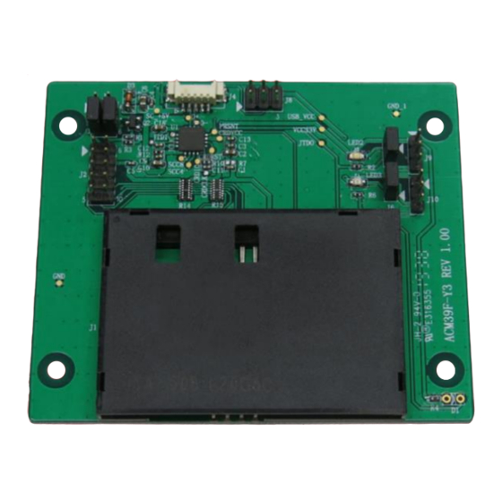
Summary of Contents for ACS ACM39U-Y
- Page 1 ACM39U-Y Reader Module User Manual V1.00 Subject to change without prior notice info@acs.com.hk www.acs.com.hk...
-
Page 2: Table Of Contents
Figure 6 : ACM39U-Y Card Detection Signal Configuration ..............10 Figure 7 : ACM39U-Y Extended Card Connector Configuration............12 Figure 8 : ACM39U-Y External Card Connection Diagram ..............13 Figure 9 : ACM39U-Y Extended Power and Card Operation Status Signals ........14 Page 2 of 14 www.acs.com ACM39U-Y –... -
Page 3: Introduction
The ACM39U-Y comes in two variants: CCID and non-CCID. This document is a guide to the use and configuration of the various connectors of the ACM39U-Y, so that users can maximize its convenience and adaptability in various embedded environments. -
Page 4: Configuring The Led Operation Status
To enable the LED for smart card operation status (see D2), connect a jumper to (J5) (see Figure 1). 2.1.2. Enable LED for Power Status To enable the LED for power status (see D3), connect a jumper to (J6) (see Figure 1). Page 4 of 14 www.acs.com ACM39U-Y – User Manual info@acs.com.hk www.acs.com.hk Version 1.00... -
Page 5: Led Behaviors
Power No card present/ Slow flash Card power off Green Card power on Fast flash Card operation The LED turns on for 200 ms every 2 seconds. Page 5 of 14 www.acs.com ACM39U-Y – User Manual info@acs.com.hk www.acs.com.hk Version 1.00... -
Page 6: Connecting The Acm39U-Y To Another Device Via Usb
3.0. Connecting the ACM39U-Y to Another Device via USB The ACM39U-Y has a USB port that can be used to connect the module to another device. To do this: Option 1: Connect socket (J4) via USB cable to another peripheral device (see Figure 2). -
Page 7: Figure 2: Acm39U-Y Usb Configuration
Figure 2: ACM39U-Y USB Configuration Page 7 of 14 www.acs.com ACM39U-Y – User Manual info@acs.com.hk www.acs.com.hk Version 1.00... -
Page 8: Configuring Card Detection
Normal Open Normal Closed Since the ACM39U-Y offers an extendable smart card connector signal, you can choose the type of card detection to be used on the other end of the device. To choose a type of card detection: 1. -
Page 9: Connecting To Card Insertion Signal
5.1. Connector Pin Details You can make use of pin 1 and pin 6 of J2 to get the signal of card insertion. When a card is inserted to the ACM39U-Y, pin 6 will be connected to GND. Card detection pin Page 9 of 14 www.acs.com... -
Page 10: Card Detection Pin Behaviors
To get the card detection signal in (J2), connect a jumper in (J3) as shown in the connection diagram. Figure 5: Card Detection Signal Pin Diagram Note: This setting means that the ACM39U-Y card connector is set to Normal Open as mentioned in the section Configuring Card Detection. If Normal Closed card detection is set, the behaviors indicated in the section Card Detection Pin Behaviors are reversed. -
Page 11: Configuring Extended Card Connector
6.0. Configuring Extended Card Connector The ACM39U-Y is designed to offer an extendable smart card connector signal that will best fit the embedded system. The ACM39U-Y may be connected to another device that is equipped with a smart card connector to interface with the smart card. -
Page 12: Figure 7: Acm39U-Y Extended Card Connector Configuration
Figure 7: ACM39U-Y Extended Card Connector Configuration To use the external card connector, the selection resistor jumper should be changed. The resistor array should be soldered on R14 instead of R15. Page 12 of 14 www.acs.com ACM39U-Y – User Manual info@acs.com.hk... -
Page 13: Figure 8: Acm39U-Y External Card Connection Diagram
Figure 8: ACM39U-Y External Card Connection Diagram Page 13 of 14 www.acs.com ACM39U-Y – User Manual info@acs.com.hk www.acs.com.hk Version 1.00... -
Page 14: Extending Power And Card Operation Status Signals
1. Connect a jumper to (J9) and (J10) for the LED status of power and card signals. USB VCC USB VCC Not connected Not connected Connected signal from the MCU Figure 9: ACM39U-Y Extended Power and Card Operation Status Signals Page 14 of 14 www.acs.com ACM39U-Y – User Manual info@acs.com.hk www.acs.com.hk...


Need help?
Do you have a question about the ACM39U-Y and is the answer not in the manual?
Questions and answers