
Related Manuals for ACS TC 120


Summary of Contents for ACS TC 120
- Page 1 TC 120 Water Temperature Control Units OPERATION AND INSTRUCTION MANUAL TC 120 Part Number: 682.98767.00 Revision: 10/04/18 TC 120 682.98767.00 • 8/22/2018...
- Page 2 _________________________ _________________________ _________________________ _________________________ _________________________ _________________________ We are committed to product improvement. Specifications, appearance, and dimensions described in this manual are subject to change without notice. DCN No. ____________ © Copyright 2018 All rights reserved. TC 120 682.98767.00 • 10/04/2018...
- Page 3 If the shipment is not what you ordered, please contact customer service at 262.641.8600. Have the order number and item number ready. Hold the items until you receive shipping instructions. Returns Do not return any damaged or incorrect items until you receive shipping instructions from the shipping department. TC 120 682.98767.00 • 10/04/2018...
-
Page 4: Table Of Contents
Identifying Mechanical Controls and Features ............24 To Process Probe ....................24 Safety Thermostat ....................24 Pressure Relief Valve ..................24 Pumps .......................24 Heaters ......................25 Solenoid Valves ....................25 Motorized Modulating Valves ................25 Water Hammer Arrestor (Shock Stop) ..............25 TC 120 682.98767.00 • 10/04/2018... - Page 5 CHAPTER 6: UNIT MAINTENANCE ........36 Preventative Maintenance ..................36 Draining ......................36 Every Six Months ....................36 Corrective Maintenance ................... 37 Pumps and Seals ....................37 Heaters ......................38 Solenoid Valves ....................38 Electrical Connections ..................... 38 Safety Devices ......................39 TC 120 682.98767.00 • 10/04/2018...
- Page 6 CHAPTER 7: TROUBLESHOOTING ........40 Introduction ......................40 CHAPTER 8: APPENDIX ............43 Customer Satisfaction Warranty Program ..............43 Technical Specifications ..................44 Drawings and Diagrams................... 44 Spare Parts List ....................... 47 Technical Assistance ....................48 TC 120 682.98767.00 • 10/04/2018...
-
Page 7: Chapter 1: Safety
WARNING indicates a potentially hazardous situation or practice that, if not avoided, could result in death or serious injury. Caution! CAUTION indicates a potentially hazardous situation or practice that, if not avoided, may result in minor or moderate injury or in property damage. TC 120 682.98767.00 • 10/04/2018... -
Page 8: General Safety Regulations
Organize a safety committee or group, and hold regular meetings. Promote this group from the management level. Through this group, the safety program can be continually reviewed, maintained, and improved. Keep minutes or a record of the meetings. TC 120 682.98767.00 • 10/04/2018... - Page 9 DO NOT wear loose clothing or jewelry, which can be caught while working on the temperature control unit. In addition, cover or tie back long hair. Clean the temperature control unit and surrounding area DAILY, and inspect the machine for loose, missing or broken parts. TC 120 682.98767.00 • 10/04/2018...
- Page 10 DO NOT start and run the temperature control unit until you are sure all parts are functioning correctly. BEFORE you turn the temperature control unit over to the operator for production, verify all enclosure panels, guards and safety devices are in place and functioning properly. TC 120 682.98767.00 • 10/04/2018...
-
Page 11: Warnings And Precautions
Read and follow these operation and installation instructions when installing, operating, and maintaining this equipment. If these instructions become damaged or unreadable, additional copies are available from the manufacturer. TC 120 682.98767.00 • 10/04/2018... - Page 12 ANY reason. They should be checked frequently by a qualified mechanic for proper operation. NEVER modify the machine configuration or any individual component without written notice from the factory. TC 120 682.98767.00 • 10/04/2018...
- Page 13 We have long recognized the importance of safety and have designed and manufactured our equipment with operator safety as a prime consideration. We expect you, as a user, to abide by the foregoing recommendations in order to make operator safety a reality. TC 120 682.98767.00 • 10/04/2018...
-
Page 14: Chapter 2: Functional Description
The TC 120 water temperature control units are reliable, accurate, and easy-to-use process temperature control units. They are self-contained, portable, and shipped ready to use. The TC 120 water temperature control units are designed to circulate water through your process and to precisely, automatically, and reliably maintain it at a specified temperature. -
Page 15: Models Covered
Models Covered This manual provides operation, installation, and maintenance instructions for the TrueTemp™ TC 120 and Sterlco® TC 120 series water temperature control units. Model numbers are listed on the serial tag. A model number followed by Q indicates a specially constructed unit, and not all information in this manual may apply. -
Page 16: Available Options
Temperature control unit systems are available with options to tailor the unit to your requirements. Some are factory installed; some can be retro-fitted in the field. Consult ACS Group sales for more information. Available TCU options include: Digital flow meter with: ... - Page 17 Audible and visual general fault alarm Electrical operation available in 208, 460, and 575 volts, 60 Hz; 380, and 415 volts, 50 Hz UL/ UL-listed electrical subpanel, CE Compliance per EMC Low Voltage Directive TC 120 682.98767.00 • 10/04/2018...
-
Page 18: Chapter 3: Installation
Chapter 3: Installation Installation Location Considerations The TC 120 Temperature control systems are portable and can be installed almost anywhere. As with all equipment installations, follow all applicable codes and regulations. The recommended ambient temperature range from +14ºF (-10ºC) to a maximum operating ambient temperature of 131F (55ºC). -
Page 19: Piping Considerations For High Mobility Installations
Raw Water Water treatment is vital in any piping system. In some cases, raw water may be used in the system without problems; in other cases, it can result in large deposits of scale and corrosion. TC 120 682.98767.00 • 10/04/2018... -
Page 20: Distilled Water
ACS offers a complete line of water treatment equipment. Contact your ACS sales representative for water testing and treatment options. Distilled Water Non-ferrous (brass, copper or high-temperature plastic) piping is recommended for distilled water processes. Deionized Water Stainless steel (316 SS minimum) or PVC plastic components must be used with deionized water. -
Page 21: Water Out
Making System Purge Connections TC 120 temperature control systems equipped with the System Purge option have a compressed air inlet marked MOLD PURGE. Connect to a clean, dry 100 psig (68 kPa/6.9 bar) air line. Install your own shutoff valve to prevent process liquid from backing up into the plant air piping if the compressed air is turned off and the check valve fails. -
Page 22: 3-10 Making Electrical Connections
3-10 Making Electrical Connections TC 120 temperature control systems are designed for three-phase voltage operation. Refer to the unit nameplate for proper voltage and amperage requirements. Make sure you provide a correctly sized and protected supply of electrical power to the unit. - Page 23 3. Voltage must be within plus or minus ten percent (10%) of the nameplate rating. 4. Make sure your installer provides external protection. Figure 7 Typical Electrical Wiring Schematic Please refer to the electrical wiring diagrams supplied with your unit’s Customer Information Packet. TC 120 682.98767.00 • 10/04/2018...
-
Page 24: Chapter 4: Identifying Controls And Features
The unit continues to pump water through the system to prevent heater damage. The ACS Group recommends that you install an audible or visual alarm to the terminals provided. Factory installed alarms are available;... -
Page 25: Heaters
Pump Starter TC 120 temperature controller’s high quality IEC-rated pump motor starters are industrial grade motor controls with overload and overcurrent protection with manual reset. Transformer High quality industrial design transformers are specified to suit incoming voltage on the application and provide 115 VAC control voltage. -
Page 26: Electricals
The controller is an easy-to-operate microprocessor-based PID control device. When the process reaches the set point, the PID control cycles the cooling valve and/or immersion heater to maintain the proper leaving water temperature. TC 120 682.98767.00 • 10/04/2018... -
Page 27: Controller Display
See Figure 4.1 Page Key From any display – press to return to the HOME display. Enter Key Press to select a new parameter. If held down it will continuously scroll through the parameters. TC 120 682.98767.00 • 10/04/2018... -
Page 28: Digital Flow Meter
Do not change any of the control settings without consulting the ACS Group Service Department. The ACS Group warranty does not cover temperature control unit failures from tampering with controller settings! Down Key Each press of the key decrements or reduces the values or settings on Down Arrow Set Value display. -
Page 29: Heater On Indicator
AIR PURGE When water no longer comes out of the cooling WATER OUT line and only air comes out, the purge is complete. Use caution when removing these lines; air pressure is still present inside. TC 120 682.98767.00 • 10/04/2018... -
Page 30: Using Graphic Panel Buttons
Push the button to silence the alarm. ALARM SILENCE The optional mechanical high temperature safety alarm is interlocked with the heater. When triggered, the heater cuts out and the pump continues to run. TC 120 682.98767.00 • 10/04/2018... -
Page 31: Controller Internal Switches
If the controller does not work properly, or you suspect someone has accidentally changed some settings, there are two things to do. First, perform the Auto-Tune procedure described in Section 5-3. If that doesn’t work, restore the controller to the original factory settings. TC 120 682.98767.00 • 10/04/2018... -
Page 32: Chapter 5: Startup And Operation
Chapter 5: Startup and Operation Introduction The checklist below outlines start-up procedures for TC 120 water temperature control units. This list assumes that installation information located in this manual has been read and followed. Startup Checklist Check the shipping papers against the serial tag to make sure that system size, type, and voltage is correct for the process under control. -
Page 33: Starting The Temperature Control Unit
All electrical installation and repairs should be done by a qualified electrician. Ground the unit in accordance with electrical codes. Never attempt any repairs without first opening and locking out the main disconnect. Never deactivate or neutralize any safety device. TC 120 682.98767.00 • 10/04/2018... -
Page 34: Sequence Of Operation
Check for correct pump rotation direction by looking at the motor impeller. Press the START button and the STOP button, and note the direction that the motor turns. Rotation should be clockwise when viewed from the motor end. Note: Make sure that a qualified electrician performs the following steps. TC 120 682.98767.00 • 10/04/2018... -
Page 35: Shutting Down The Temperature Control Unit
Cool the unit down by selecting a set point of zero ( °F). Let the unit stabilize at one temperature close to the incoming water temperature, then press the STOP button. Now press the VENT button to relieve any remaining pressure in the system. TC 120 682.98767.00 • 10/04/2018... -
Page 36: Chapter 6: Unit Maintenance
Inspect the power cable, especially at the entrance point to the unit. This inspection should be made by a qualified electrician. Check for leaks, especially under the pump, as it may indicate a worn pump seal. TC 120 682.98767.00 • 10/04/2018... -
Page 37: Corrective Maintenance
If the shaft is free to turn, next check that the motor overloads are set, check for blown fuses, and finally check the power supply on each leg to the motor. A qualified electrician should check the motor and its circuit. TC 120 682.98767.00 • 10/04/2018... -
Page 38: Heaters
Sluggish operation, excessive leakage, and/or noise indicate cleaning is necessary. Inspect the components for excessive wear while the valve is disassembled. Rebuild kits are available from the ACS Group Parts Department. Electrical Connections Make sure that a qualified electrician inspects all electrical components and connections every six (6) months for secure attachment and ground connections. -
Page 39: Safety Devices
Drain and flush the unit every six (6) months to remove sediment buildup. Completely drain the unit and carefully blow out the piping with pressurized air before placing the unit in storage. TC 120 682.98767.00 • 10/04/2018... -
Page 40: Chapter 7: Troubleshooting
Unit does not run. Low water pressure light on. WATER IN or CITY WATER MAKEUP. Water supply to unit is turned Open water supply. off. Reset and test each leg for Pump overload light on. balanced amp draws. TC 120 682.98767.00 • 10/04/2018... - Page 41 Solenoid valve is not Set process temperature to operating, but COOL LED is minimum and check for magnetism on solenoid coil top. Check coil resistance. If M Solenoid coil circuit is open. range, replace solenoid coil. TC 120 682.98767.00 • 10/04/2018...
- Page 42 Manually open valve to clear seat seat. of material. Relief valve leaks. Reduce WATER IN or MAKEUP High system pressure. water pressure. Unit runs continuously Unit under-sized for cooling or heating, Call sales representative. application. and cannot attain set point. TC 120 682.98767.00 • 10/04/2018...
-
Page 43: Chapter 8: Appendix
Refer to this manual for assistance in installing and maintaining a highly efficient machine. Questions regarding areas that are not covered in the manual should be referred to the customer service manager at the factory at 262.641.8600. TC 120 682.98767.00 • 10/04/2018... -
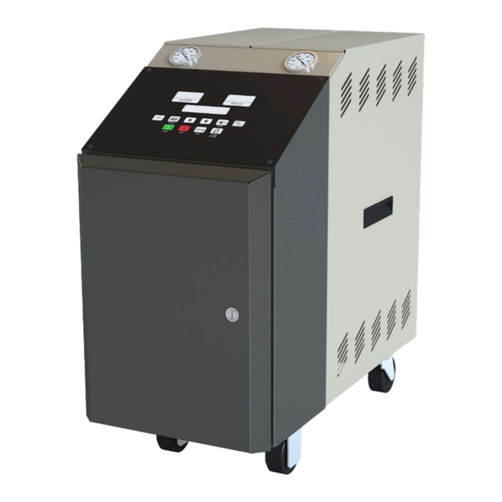
Page 44: Technical Specifications
Technical Specifications Table 1: TC 120 Specifications Dimensions Shipping Pump weight psig lbs. ¾ 0.56 113.6 172.4 0.75 132.5 206.9 1.50 189.3 206.9 28¾” 73.0 35.6 28 71.1 2.24 227.1 241.3 3.73 340.7 344.8 7½ 5.60 454.2 344.8 Table 2: Additional Specifications Model ... - Page 45 Figure 8.1 Typical TC 120 Water Temperature Control Unit Figure 3 Typical Piping Schematic PRESSURE RELIEF VALVE DELIVERY AUTOMATIC AIR PURGE (OPTIONAL) DELIVERY SAFETY PRESSURE (OPTIONAL) SENSOR THERMOSTAT GAUGE IMMERSION FLOW CHECK HEATER METER VALVE DELIVERY CHECK VALVE PUMP AIR SUPPLY...
- Page 46 Figure 4 Pump Curves; 60 Hz Figure 5 Pump Curves; 50 Hz TC 120 682.98767.00 • 10/04/2018...
-
Page 47: Spare Parts List
250°F (121°C) safety thermostat 724.00665.00 300°F (149°C) safety thermostat 724.00666.00 Relief valve 044.00138.00 “K” type thermocouple 701.00124.00 1000 ohm RTD probes 692.07369.29 Temperature Control Module (Eurotherm P116) with relay outputs 724.00992.00 Temperature Control Module (M2C) 601.86861.00 TC 120 682.98767.00 • 10/04/2018... -
Page 48: Technical Assistance
Technical Assistance PARTS SUPPORT ACS welcomes inquiries on all your parts needs and is dedicated to providing excellent customer service. The ACS Customer Service Group will provide your company with genuine OEM quality parts manufactured to engineering design specifications, which will maximize your equipment’s performance and efficiency.
Need help?
Do you have a question about the TC 120 and is the answer not in the manual?
Questions and answers