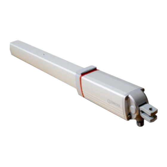
Erreka Vulcan D User Manual
Hydraulic operator
Hide thumbs
Also See for Vulcan D:
- Quick installation and programming manual (4 pages) ,
- Quick installation and programming manual (29 pages)
Table of Contents
Advertisement
Quick Links
INDEX
Symbols used in this manual__________________________________ 42
Importance of this manual ___________________________________ 42
Envisaged use ______________________________________________ 42
Installer's qualifications ______________________________________ 42
Automatic safety elements ___________________________________ 42
Elements of the complete installation __________________________ 43
General features of the operator ______________________________ 44
Main operator parts_________________________________________ 44
Technical features of the operator _____________________________ 45
Manual operation __________________________________________ 46
Declaration of conformity ____________________________________ 46
Unpacking_________________________________________________ 47
Content___________________________________________________ 47
Required tools _____________________________________________ 48
Initial conditions and checks __________________________________ 48
Installing the operator _______________________________________ 49
Final preparation ___________________________________________ 57
Maintenance_______________________________________________ 58
Failure diagnosis____________________________________________ 58
Spare parts ________________________________________________ 59
Scrap _____________________________________________________ 59
English
42
43
47
48
58
VULCAN D Hydraulic operator
41
Advertisement
Table of Contents

Related Manuals for Erreka Vulcan D


Summary of Contents for Erreka Vulcan D
-
Page 1: Table Of Contents
Required tools _____________________________________________ 48 Initial conditions and checks __________________________________ 48 Installing the operator _______________________________________ 49 Final preparation ___________________________________________ 57 Maintenance and diagnosis of failures Maintenance_______________________________________________ 58 Failure diagnosis____________________________________________ 58 Spare parts ________________________________________________ 59 Scrap _____________________________________________________ 59 VULCAN D Hydraulic operator... -
Page 2: General Safety Instructions
Standard EN 12453:2000. The safety of the complete installation depends on For further details, see “Fig. 1 Elements of the all the elements installed. Install only Erreka complete installation” on page 43. components order guarantee proper operation. -
Page 3: Description Of The Product
20 m Elements of the complete installation Fig. 1 For greater safety, Erreka recommends installing the The safe and correct operation of the photocells (4) and (10). installation is the responsibility of the installer. VULCAN D Hydraulic operator... -
Page 4: General Features Of The Operator
DESCRIPTION OF THE PRODUCT GENERAL FEATURES OF THE OPERATOR The VULCAN D (residential) operator is constructed to VUA Models (with slow down) form part of a swing gate automation system. The The VUA models have a slow-down system in the... -
Page 5: Technical Features Of The Operator
In closing Dual lock With unlocked operators the gate can be moved without unlocking the operator, at a speed similar to the operator speed. When unlocking, the gate remains free and can be moved more quickly. VULCAN D Hydraulic operator... -
Page 6: Manual Operation
E240B Locked Unlocked DECLARATION OF CONFORMITY Erreka Automatismos declares that the VULCAN D The VULCAN D electromechanical operator complies electromechanical operator has been designed for use with safety legislation in line with the following in a machine or for assembly along with other elements... -
Page 7: Unpacking And Contents
10 Hydraulic motor unit 16 Rear support Fork 11 Spindle cover 17 Release key Fork horizontal pin 12 1m cable with cable Gland cover screws connectors Gland cover 13 Spindle cover screws VULCAN D operator content Fig. 3 VULCAN D Hydraulic operator... -
Page 8: Installation
INSTALLATION REQUIRED TOOLS Marker pencil Set of screwdrivers Spirit level Fixed wrenches Tape measure Socket wrench (8 mm) Set of Allen keys Welding machine Use the welding machine in line with the user Lubrication grease (graphite or lithium grease) manual. -
Page 9: Installing The Operator
The assembly levels depend on the opening angle of the gate and the following factors: • Inward or outward opening of the gate. There are therefore two different cases, as explained below (each case is represented by way of its corresponding diagram, table and chart). VULCAN D Hydraulic operator... - Page 10 INSTALLATION Inward opening The installation levels must be respected in order for the operator to work correctly. 80mm 960mm M240C Opening Level A Level B angle 80º 85º 90º 90º 95º 100º 110º Use of the chart: Multiple A-B pairs can be chosen for a specific 1 Use the chart to select the specific level for the opening angle.
- Page 11 (size 2 Following the grid, move from the level to the of the pillar, presence of walls, etc). line corresponding to the required opening angle. 3 Following the grid, move to the other level. VULCAN D Hydraulic operator...
- Page 12 INSTALLATION Procedure Position the front and rear supports 1 Attach the front (1) and rear (2) supports, keeping strictly to the levels shown in the previous section. The installer should choose the support attachment system (welding, screwing, molding, etc) in accordance with the composition of the material to which the supports are attached (metal, concrete, etc).
- Page 13 2 Position the vertical shaft (3) and secure with the nut (4). P240D Mount the cover and the top 1 Mount the cover (1), ensuring it fits in the body of the operator. 2 Secure the cover using the locking screws (2). P240E VULCAN D Hydraulic operator...
- Page 14 INSTALLATION Loosen the discharge screw CAUTION. VERY IMPORTANT: Once the operator is mounted on the supports, turn the discharge screw (1) once to allow the correct operation of the hydraulic system. If you have to dismount the operator from its supports, first tighten the discharge screw in order to prevent the hydraulic fluid from leaking.
- Page 15 Position the cover and tighten the gland 1 Position the cover (1) in its housing (2) and secure with the screws (3). 2 Tighten the gland (4) to ensure the electrical cable input (5) is seal tight. P240U VULCAN D Hydraulic operator...
- Page 16 INSTALLATION Adjust the opening and closing pressure Clockwork turning increases the pressure for both The opening and closing pressures must be screws. Anti-clockwork turning reduces adjusted in line with the size and weight of the pressure. gate. 1 Open the cover (1). 2 OPENING PRESSURE: screw (2).
-
Page 17: Final Preparation
• Children must not be allowed to play with the device. • Cleaning and maintenance must not be carried out by children unless supervised. VULCAN D Hydraulic operator... -
Page 18: Maintenance And Diagnosis Of Failures
MAINTENANCE AND DIAGNOSIS OF FAILURES MAINTENANCE 1 Regularly check the installation in order to discover Before carrying maintenance any imbalance or signs of deterioration or wear. Do operation, disconnect the device from the not use the device if any repair or adjustment is power supply. -
Page 19: Spare Parts
In this cause environmental contamination. manner possible accidents and damage to adjacent facilities will be avoided. VULCAN D Hydraulic operator...
Need help?
Do you have a question about the Vulcan D and is the answer not in the manual?
Questions and answers