
Subscribe to Our Youtube Channel
Related Manuals for Rabe Corvus 5 Series


Summary of Contents for Rabe Corvus 5 Series
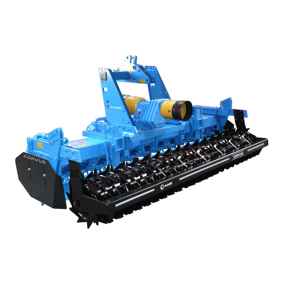
- Page 1 Order no. 9900.00.61EN05 Operating instructions Rotary harrow Corvus VKE 4000 K - 5000 K, 8000 K from series 5 Corvus VKE 6000 K from series 4...
- Page 5 For Your Own Safety In this enclosure to the operating instructions you will find some general rules of conduct explaining how to operate the implement correctly - and some safety advice which we advise you to observe for your own safety! The list is very extensive, and some of the advice does not specifically relate to the implement supplied.
- Page 6 2. General Safety Advice and Accident Prevention Regulations • Before starting up your implement and tractor, please check that it is roadworthy and operatively safe. • Please observe all generally valid safety and accident prevention regulations. • The warnings and signs found on the implement are there to provide essential data needed to operate the unit safely.
- Page 7 • Road, steering and braking performance will be influenced by mounted or attached implements and ballast. Therefore make sure that you have sufficient steering and brake capability. • Account for the width of the implement and its working load when taking corners. •...
- Page 8 • When using the external controls to operate the three-point linkage, keep clear of the area between the tractor and the implement. • When the implement is in transportation position, always ensure that the tractor’ s three-point linkage is sufficiently locked at the side. •...
- Page 9 • Before engaging the PTO make sure that the area of danger around the implement is free of bystanders. • Never engage the PTO when the engine is switched off. • When working with the PTO, keep the area around the rotating PTO and drive shaft clear of any bystanders.
- Page 10 • Liquids that leak at high pressure (hydraulic oil) can penetrate the skin and cause serious injury! In the event of injury, consult a doctor immediately. Risk of infection! • Before working on hydraulic units, lower the implement, depressurize the system, switch off the engine and remove the ignition key.
- Page 11 • When performing electrical welding work on a tractor with a mounted implement disconnect any cables connected to the generator and the battery. • Gas tanks must only be filled using nitrogen to avoid risk of explosion.! • Spare parts must at a minimum comply with the technical requirements given by the manufacturer of the implement.
- Page 13 The intended use comprises also the compliance with the specified operating-, maintenance and servicing instructions, such as the kW/HP limitation, as well as the exclusive use of original spare parts. The use of third party accessories and/or third party parts (wear and spare parts) not approved by Rabe voids any guarantee.
-
Page 15: Table Of Contents
Table of contents Machine data .......................5 Mounting heavy attachments ..................6 Articulated shafts between the gears ..................7 Loading instructions ........................7 Safety instructions .....................8 Attachment ........................9 Articulated shaft (Tractor/implement) ..................9 Transport position ........................10 Working position ........................10 Set down the rotary harrow .......................10 ........................11 Harrows speeds ........................12 Power take-off drive shaft ......................13... -
Page 17: Machine Data
Machine data Rotary Harrow Corvus VKE...K Lengths in mm (approx.) Weight in for tractors Basic variant approx. kg up to kW/HP VKE, V 4000 K 2870 4170 4080 2085 VKE, V 4500 K 3065 4660 4570 2330 VKE, V 5000 K 3260 220/300 5150... -
Page 18: Mounting Heavy Attachments
Mounting heavy attachments Important additional information for the combination of tractor and attached implements The attachment of implements to the front and rear three point linkage must not result in the total permitted weight, axle load or tyre capacity of the tractor being exceeded. -
Page 19: Articulated Shafts Between The Gears
Transport width: approx. 275 cm Sound pressure level: Noise increase at the ear of the tractor driver at the standard power take-off speed < “70 dB(A)” Maximum length of the combination (tractor + implement) 12 m -Width 2.55m, max. 3m -Max. -
Page 20: Safety Instructions
Safety instructions During coupling and uncoupling, no person may stand between the tractor and the implement, nor should anyone stand there with actuation of the hydraulic control! Risk of injury! Set tractor lifting hydraulics to "position control' before coupling and uncoupling! Check tractor and implement for operational and traffic safety prior to every operation! Ensure sufficient steering safety;... -
Page 21: Attachment
Attachment Make sure that the connection dimensions match (cat. of tractor/rotary harrows); with Cat. “III short”, use attachment sleeves. Set lower link of the tractor to the same height and limit them to a low lateral tolerance after mounting; attach to side for transport. To reduce the friction forces in the lower link arresting hook and to avoid damage to the lower link coupling elements, a loose ball bush... -
Page 22: Transport Position
Transport position Power take-off switched off! Lift the implement and secure the packer rollers in the bottom position - with plugs in the outside of the hole strip (5/1). After folding the implement in, the folding cylinders lock automatically. Make sure that there is sufficient clearance with the tail lights set up. -
Page 23: Use
Operate the rotary harrow with 1000 series power take-off. Only switch the power take-off on and off if the rotary blades are a few cm above the ground. If the rotary harrow is to be lifted higher, switch off the power take-off. The rotary harrows and thus the gear unit input shaft must be horizontal;... -
Page 24: Harrows Speeds
Harrows speeds Harrows speeds and travel speed (max. approx. 8 km/h) definitively influence the desired crumbling effect. Select the lowest possible speed, which still provides good results. High harrows speeds cause increased blade wear. Centre control gear: 3 gears (11/1,2,3). Attention: only switch when stationary! For the switching and coupling of the articulated shaft, the gear/drive strand can be turned with a... -
Page 25: Power Take-Off Drive Shaft
Power take-off drive shaft The power take-off drive shaft has the same rotational speed, as that which powers the tractor and always runs with it. Always leave power take-off guard on the implement! Ground guide plates (13/1) They guide the ground “inward” and close the “gap”... -
Page 26: Maintenance
Maintenance When working on the mounted implement, switch off the power take-off, switch off the engine and remove the ignition key! Do not work on the implement while it is engaged! - secure the raised implement by additional means to prevent undesired lowering! Before performing work on the hydraulic system, lower the unfolded implement and depressurise the system! -
Page 27: Oil Change
Oil change WARNING Risk of burning due to hot surfaces. The transmission oil and thus the gears themselves become very hot during operation due to friction. • Do not carry out work on the gears and gearboxes immediately after operation; wait for them to cool down first. -
Page 28: Gearbox - Change Transmission Oil
Fill quantity Centre gear (12.1/1) 6.8 l Side gear (12.1/2) Max. 4,5 l NOTE Excessive quantities of oil cause the gears to overheat. 12.1 Oil change - Centre control gear Secure the folded, raised implement by additio- nal means to prevent undesired lowering! Place a catch pan below the oil drain screw (15/2) and unscrew it. -
Page 29: Tooth Packer Roller
Use the original bolts for the blade fastening, inserted from below (bolt head on the blade side). Tighten with torque wrench: 380 Nm RABE recommends using rotary blades with RABID hard coating on stony ground or the like = significantly longer service life. -
Page 30: Attention / Transport
Lighting devices – with warning signs – can also be subsequently obtained from RABE. The warning triangle (30/1) must be mounted in the centre for transport on public roads in Poland. -
Page 31: Locations Of The Warning Signs On The Implement
Locations of the warning signs on the implement Subject to technical modifications 05/2003... - Page 33 The pictograms are an integral part of the implement. Warning labels should be visible (dirt-free) at all times, and replaced if damaged – they can be ordered from Rabe under the relevant pictogram number (Pict. No.). Pict. No. Position-No.
- Page 34 Danger of squeezing. Keep away! Rotating tools. Keep away! Do not grasp behind safety devices or covers. Never carry out work unless PTO-drive is disengaged and the engine is stopped. Danger of Life by load from top! Lift Turbodrill only with empty hopper and never together with rotary harrow.
- Page 35 Danger of leg injuries when elements may suddenly swing out. Keep away! Grease all marked grease nipples regulary. The reset force can be increased by adjusting the bolt (kN) to the left (!). Reduce by turning to the right. There must be always a minimum clearance a of 1 mm.
- Page 36 9998.02.85 Hydraulic accumulator is pressurized. Repair and replace only as prescribed in the Technical Manual provided. Oil fl ow path: Forward: ”Lift” 9998.06.01 Oil fl ow path: Return ”Lower” or ””Tank” 9998.06.02 The maximum operating pressure for the hydrau- lic system must not exceed 200 bar! 9998.02.80 The maximum rotational frequency of the PTO max.1000/min...
- Page 37 9998.02.88 Safety catch for road transportation on combi- wheel. Disengage safety catch before working in the fi eld. Technical data subject to change...
- Page 40 Rabe Agri GmbH D-49152 Bad Essen Am Rabewerk 1 Telefon: +49((0)5472-771 0 Telefax: +49(0) 5472-771 190 + 195 Geräteverkauf Telefax: +49(0) 5472-771 100 Ersatzteilverkauf info.rabewerk@t-online.de www.rabewerk.de...
Need help?
Do you have a question about the Corvus 5 Series and is the answer not in the manual?
Questions and answers