Table of Contents

Related Manuals for Rabe Condor 150


Summary of Contents for Rabe Condor 150
- Page 1 ( T R A N S L AT I O N O F T H E O R I G I N A L O P E R AT I N G I N S T R U C T I O N S F R ) Serial-No. Condor 150 Fully mounted reversible plough...
- Page 3 UICK START ONDOR Preparing the tractor 1st pass Check the pressure of the tyres. Adjust the alignment. - It must be identical on each side of the tractor, both at the - The top link must be aligned with the tractor centreline. front and back.
-
Page 5: Table Of Contents
ABLE OF CONTENTS 5.1.1 Tractor equipped with link arms with fixed ball INT R OD U CTI ON joints ............21 5.1.2 Tractor equipped with link arms with removable ball joints ........21 5.1.3 Attachment of the link .......21 Instructions ..........7 5.1.4 Electrical connection of the signalling Product documentation ........7... - Page 6 ABLE OF CONTENTS M AIN TE NA NC E Protection of the environment...... 42 10.1 Soil contamination ..........42 10.2 Worn tyres ............42 Cleaning ............. 42 Inspection ..........42 12.1 Checking the hydraulic system ......43 12.1.1 Identification of a hydraulic hose ....43 12.2 Lubrication and greasing ........44 Troubleshooting and repair ......
-
Page 7: Introduction
Telephone number of your agent or dealer: ............................Explanation of type designation: 1.4.1 Type plate Condor 150 The type plate contains the following information: - 150: Frame dimensions 150 mm x 150 mm Associated documents - 1 operator's manual. -
Page 8: Safety Instructions And Rules
PERATOR S MANUAL ONDOR AFETY INSTRUCTIONS AND RULES 2.1.4 Hydraulic circuit and couplings Safety instructions CAUTION: 2.1.1 General instructions The hydraulic circuit is subject to high pressures. CAUTION: The risks of accidents during use, maintenance or and cause fatal injuries. Immediately consult a doctor in the repair of the implement can be reduced if you follow event of injury. -
Page 9: Transport On The Public Highway
PERATOR S MANUAL ONDOR 2.1.6 Transport on the public highway 2.1.7 Maintenance The implements must always be transported in accordance The maintenance area must be clean, dry, well ventilated and with the applicable directives and regulations relating to the well lit. prevention of accidents, road safety and occupational health. -
Page 10: Safety Stickers
PERATOR S MANUAL ONDOR 2.1.9 Safety stickers CAUTION: IMPORTANT: Take care not to damage the safety stickers when Replace damaged or missing stickers. washing the implement. Locations of the safety stickers. UI 1831 UI 1828 UI 1860 UI 1860 UI 1845 UI 1841 UI 1841 UI 1856... -
Page 11: Use
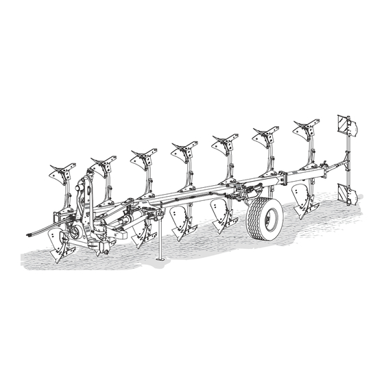
PERATOR S MANUAL ONDOR ESCRIPTION OF THE IMPLEMENT General views Legend Top link yoke hitch Shaft Lower link yoke hitch Parking stand location (detached plough) Transport and working depth wheel Lighting and signals Headstock Alignment arm Front furrow width adjustment arm 10 Multi-position shoe 11 Ploughing elements 9901.00.29EN01 - 09/2017... -
Page 12: Technical Specifications
PERATOR S MANUAL ONDOR Part Turn over Hydraulic rollover mechanism hydraulic Inclination adjustment Frame Main frame150 x 150 mm doubled up to last but one furrow Possibility of adding extra bodies. Working width Bolt adjustable form 12’’ to 20’’ for interbody distance 90 cm Alignment adjustment With mechanical turnbuckle Inter-body clearance... -
Page 13: Dimensions And Weights
PERATOR S MANUAL ONDOR Dimensions and weights IMPORTANT: The implement dimensions and weights are provided for information purposes; they may vary according to options and equipment. IMPORTANT: After use, the weight of the implement may be increased by the accumulation of soil or residues. Number of Inter-body Working width per body... -
Page 14: Hydraulic Suspension On The Top Link
PERATOR S MANUAL ONDOR 3.6.1 Hydraulic suspension on the top link Headstock beam linkage Swinging due to the weights and length of the implements is compensated by the hydraulic suspension, a hydraulic set point tie rod. This system absorbs some of the forces that cause the tipping phenomenon, it improves user comfort by acting alone or together with other systems with which the tractors are 3.6.2... -
Page 15: Working Width
PERATOR S MANUAL ONDOR Working width Depth or depth and transport wheels Multi-position shoe wheels can be mounted on the implement. There are a number of models available for this implement: Depth wheels with mecanical or hydraulic depth control. Legend Combined transport and depth wheels with mecanical or Multi-position shoe hydraulic depth control. -
Page 16: Ploughshare
PERATOR S MANUAL ONDOR 3.11 Ploughshare 3.14 Disc coulter [optional] Legend Ploughshare Reversible point Legend Spring secured version The ploughshares can be formed of just one piece or have a replaceable, reversible point. The disc coulter gives a clean cut to the furrow. 3.12 Fin coulter (Optional) thus be protected. -
Page 17: Lighting And Signals (Optional)
PERATOR S MANUAL ONDOR REPARING THE TRACTOR 3.16 Lighting and signals (optional) IMPORTANT: The user is responsible for ensuring the compliance The power required to tow your implement varies according to of the hitched assembly with the applicable the soil texture, the working conditions and the tractor equipment regulations for transport on the public highway. -
Page 18: Tyre Spacing
PERATOR S MANUAL ONDOR 4.2.2 Tyre spacing If the implement has a large number plough share pairs, the wider the tractor's track, the better the tractor/implement combination will perform. For onland ploughing Legend Min space between rear tire sidewall and the ploughing face Optimum / maximum tractor overall width Optimum tractor / implement behaviour The optimum behaviour of the tractor / implement out of furrow... -
Page 19: Ballasting The Tractor
PERATOR S MANUAL ONDOR Values Ballasting the tractor x2 the Actual Permissible permissible The implements hitched to the front and rear of the tractor may values values capacity of not exceed the total permissible load, the permissible axle loads the tyres Min. -
Page 20: Position Of The Stabilisers
PERATOR S MANUAL ONDOR Position of the stabilisers Top link. Legend Length A Length B Before hitching the implement, make sure that the thread lengths Legend Operating clearance IMPORTANT: Pins Tie rod Excess grease inside the top link can block the link bar. -
Page 21: Hitching And Unhitching
PERATOR S MANUAL ONDOR ITCHING AND UNHITCHING CAUTION: Before proceeding to connect the top link, make sure the space between the implement yoke and Hitching the implement to the tractor there is no possibility of contact between the raised position and the working position. A second check CAUTION: Make sure that hitching the implement does not is under actual working conditions. -
Page 22: Position Of Support Legs
PERATOR S MANUAL ONDOR 5.1.6 Position of support legs Unhitching the implement from the tractor Storage position CAUTION: Make sure that there is no-one in the vicinity of the implement before lowering it. IMPORTANT: Before detaching the implement, make sure moist ground, place wooden blocks to wedge the components and the support legs. -
Page 23: Hydraulic Connections
PERATOR S MANUAL ONDOR YDRAULIC CONNECTIONS - Calibration of the pressure in the headstock hydraulic suspension cylinder (independent circuit, feeding only when IMPORTANT: Pressurised oil may remain in a closed circuit. Return to reservoir allows evacuation of residual pressure. Max. hydraulic Check the service pressure of the tractor's hydraulic system. -
Page 24: Preparation Of The Implement Before Work
PERATOR S MANUAL ONDOR REPARATION OF THE IMPLEMENT BEFORE WORK Locating the adjustment points Locate the various adjustment points. Make sure that they are functioning properly and that they are well lubricated. Perform the checks before setting out for the Legend Inclination = hydraulic adjustment Calibration of the top link hydraulik suspension... -
Page 25: Working Width Adjustment
PERATOR S MANUAL ONDOR Working width adjustment Wheel angle adjustment The working width of each body can be adjusted by means of the multi-position shoe. Legend Wheel adjustment plate Legend The wheel must be parallel to the body when working. Multi-position shoe Adjustment Position... -
Page 26: Alignment Adjustment
PERATOR S MANUAL ONDOR Adjustment Reducing the plate angle (1): The wheel moves closer to the frame of the implement (2). Increasing the plate angle: The wheel moves away from the frame of the implement. IMPORTANT: When working, the wheel must always be parallel to the body. -
Page 27: Adjustment Of The Width Of The 1St Furrow
PERATOR S MANUAL ONDOR 7.5.1 Offset adjustment for work Adjustment of the width of the 1st furrow Principle Adjusting the offset allows to adjust the cutting width of the 1st Legend 1 Offset cylinder 2 Front adjustable stop It offsets the implement so that the 1st furrow works with the 3 Support rod same width as the others. -
Page 28: Adjustment For Turnover
PERATOR S MANUAL ONDOR RA6 box / offset cylinder connections - Follow the manufacturer's recommendations (values marked IMPORTANT: CAUTION: Modify the position of the hydraulic connectors according to the type of ploughing (outside or inside furrow). Ploughing RA6 box Offset cylinder 7.6.2 Tightening of wheel studs Outside furrow... -
Page 29: Calibration Of Hydraulic Suspension
PERATOR S MANUAL ONDOR Adjustment Calibration of hydraulic suspension Legend 1 Calibration valve IMPORTANT: The adjustment is made with the implement on the ground, in the working position on the right-hand Legend side. 1 Hydraulic suspension accumulator 2 Adjustment valve 3 Hydraulic suspension cylinder Caution: 4 top link yoke... -
Page 30: Changing Between Transport And Working Position
PERATOR S MANUAL ONDOR HANGING BETWEEN TRANSPORT AND WORKING POSITION DANGER: Risk of electric shock. between the implement and live high voltage power lines, there is a risk of severe, even fatal injuries - Never use the implement in the immediate vicinity of live power lines or electrical equipment. -
Page 31: Locking And Unlocking The Transport Locking Pin
PERATOR S MANUAL ONDOR 8.2.1 Mecanical locking system Locked position Legend Locking handle Locking and unlocking the transport Locking bolt locking pin drill-hole CAUTION: the mechanism. The implement is equipped with a turnover locking Unlocked position mechanism. The mechanism must be unlocked plough. -
Page 32: Hydraulic Locking System
PERATOR S MANUAL ONDOR 8.2.2 Hydraulic locking system Top link yoke in transport position The operation is performed quickly and safely.. Yoke in transport position Legend 1 Hydraulic lock in the transport position. The hydraulic suspension enables a transfer to the transport position simply by unpinning the yoke. Legend 1 top link yoke transport position 2 Clevis pin... -
Page 33: Driving On The Road
PERATOR S MANUAL ONDOR Driving on the road Changing the transport and working depth adjustment wheel to working CAUTION: position Take account of the overhang when driving on the To install the wheel in the working position. public highway. Risk of accidents involving other road users. -
Page 34: Top Link Yoke In Working Position
PERATOR S MANUAL ONDOR Top link yoke in working position Legend Legend Safety clip 1 Yoke in transport position Retaining pin 2 Lynch pin 3 retaining pin the wheel in the working position. 9901.00.29EN01 - 09/2017 - 34 -... -
Page 35: Unlocking The Transport Locking Pin
PERATOR S MANUAL ONDOR Unlocking the transport locking pin Make sure Yoke and the top link is correctly connected to the machine before removing transport locking pin. Follow the procedure chapter "8.2 Locking and unlocking the transport locking pin", page 31. IELD ADJUSTMENT CAUTION: Read this chapter in its entirety to properly... -
Page 36: First Pass
PERATOR S MANUAL ONDOR Wheel height adjustment First pass For the 1st pass, the tractor is not inside the furrow. This can alter certain adjustments, particularly that of tilting and the 1st link subsequent passes. • To increase working depth, raise the wheel: 9.2.1 Entering into the ground - D30M;... -
Page 37: Second Pass
PERATOR S MANUAL ONDOR Second pass polished and the soil slides freely, if not clean. In sticky soil, the mouldboard. 9.3.1 Alignment adjustment The alignment is correctly set when - The implement is in line behind the tractor. - The top link must be aligned with the tractor centreline. - The landsides should not apply unnecessary force to the ploughing face. -
Page 38: Lateral Levelling
PERATOR S MANUAL ONDOR 9.3.3 Lateral levelling Adjustments Ploughing outside furrow IMPORTANT: If using the hydraulic option, otherwise adjust the screws on the front axle. Set the function selector to the "inclination" position. The hydraulic control valve then serves to adjust the memory stop of the turnover cylinder. -
Page 39: Adjustment Of The Disc Coulter (Option)
PERATOR S MANUAL ONDOR 9.4.2 Disc coulter - lateral overlap adjustment Adjustment of the disc coulter (option) Adjustment tips B = Factory overlap setting approx. 5 - 6 cm. 9.4.1 Set the disc coulter working depth Once the overlap has been adjusted, check that the disc Adjustment tips coulter can perform a rocking motion in the direction of travel. -
Page 40: Disc Coulter - Adjust The Pivot Arm End Stop
PERATOR S MANUAL ONDOR 9.4.3 Disc coulter - adjust the pivot arm end stop Adjustment of Vari-Fix skimmer (option) Adjustment tips 9.5.1 Vari-Fix - Adjusting working depth Setting instructions Set the end stop with the skimmers in such a way that the disc coulter does not come into contact with the skimmer. -
Page 41: Adjustment Of Deflector (Option)
PERATOR S MANUAL ONDOR Adjustment tips when working. Legend In ground with clods to be broken, the mould boards are 1 Safety ring supposed to only skim over the tops of the ridges. Adapt the 2 Self-locking bolt working depth to the speed of the implement. Pull the self-locking bolt and set the working depth by adapting Set all the skimmers to the same working depth. -
Page 42: Maintenance
AINTENANCE ONDOR 10 P MAINTENANCE ROTECTION OF THE ENVIRONMENT CAUTION: Observe the safety instructions (see 2) before starting service work or replacing spare parts. 10.1 Soil contamination • The operator and the owner are responsible for the implement's maintenance.• Before commencing any work on the implement, switch off the engine and IMPORTANT: remove the tractor's ignition key. -
Page 43: Checking The Hydraulic System
AINTENANCE ONDOR 12.1.1 12.1 Checking the hydraulic system CAUTION: Leaks must be located with a tool. Risk of injury escaping under high pressure are able to penetrate the skin and cause serious, even fatal injuries. CAUTION: Your implement may be equipped with hydraulic accumulators. -
Page 44: Lubrication And Greasing
AINTENANCE ONDOR 12.2 Lubrication and greasing Location of lubricating nipples - overview Location of lubricating nipples Number Group Location Quantity 12 hrs. Headstock yoke rotation axis 12 hrs. cylinder joints 9901.00.29EN01 - 09/2017 - 44 -... - Page 45 AINTENANCE ONDOR Number Group Location Quantity 12 hrs. swivel arm axle front pivot pin front 12 hrs. traction point adjustment - pivot pin front traction point adjustment - adjusting arm front adjusting arm offset adjustment support rod traction point adjustment - adjusting arm rear 12 hrs.
- Page 46 AINTENANCE ONDOR Number Group Location Quantity 12 hrs. wheel hub 150 hrs Disc coulter bearing COMMENT: Grease = Commercially available lubricating grease. Grease after each washing. Regular lubrication of all moving parts ensures optimum implement operation and prolongs service life. The lubricating nipples on the pivot points enable lubrication of the axles.
-
Page 47: Troubleshooting And Repair
SW 24 stone safety device is tripped by shearing of the shear bolt. The plough body is folded back: Special RABE tool included in delivery. DANGER Risk of injury due to heavy components and sharp edges. Gloves must be worn. Risk of accidents when Repair performing repairs. -
Page 48: Body With Leg Reinforcement - Replacing The Plough Body Shear Bolt
Replace damaged bolts with OEM bolts. The plough body must be pointing downwards. Only approach the plough body from the rear. Needed tool SW 30 SW 36 SW 24 Special RABE tool. 19 mm spanner 9901.00.29EN01 - 09/2017 - 48 -... -
Page 49: Replacing The Wheel
Risk of accidents when plough body swings back. the hydraulic hoses connected. Work on level Only approach the plough body from the rear. ground, preferably on a hard, compacted surface. Use a special RABE tool. Use only new original replacement parts approved by the manufacturer. Preparations Place the implement in the the working position. -
Page 50: Spare Parts
AINTENANCE ONDOR Legend Nuts x8 wheel Turn the implement back into the transport position or leave it in the storage position. IMPORTANT: Check the tightening of the wheel studs after a few kilometres, and re-tighten if necessary. 15 S PARE PARTS In order to ensure the reliable operation and long service life of your implement, only use original spare parts from the manufacturer. -
Page 51: Tightening Torques
AINTENANCE ONDOR 15.2 Observe the tightening torques of the components. For each component, the torques vary depending on the surface condition and the lubrication. All values in the table below are for information only. Dimensions Category 8.8 Category 10.9 Category 12.9 N x m kg x m lb - ft... -
Page 52: Ce Declaration
DECLARATION 16 CE DECLARATION Mounted reversible plough (Anbau-Drehpflug) Designation: Condor 150 Type: Serial no.: erial no.: 9901.00.29EN01 - 09/2017 - 52 -... - Page 54 RABE ZI Nord Les Gaudères 37130 Langeais Frankreich Tél. (+33) 2 47 96 72 61 Fax (+33) 2 47 96 71 85 info@rabe-gb.fr www.rabe-gb.fr RABE Am Rabewerk 1 49152 Bad Essen Deutschland Tél. +49 (0) 54 72 771 - 0 Fax +49 (0) 54 72 771 -195 info@rabe-gb.de...
Need help?
Do you have a question about the Condor 150 and is the answer not in the manual?
Questions and answers