Chapters
Table of Contents

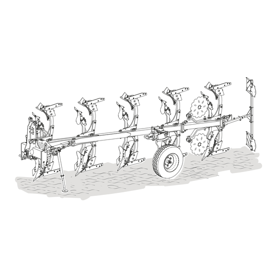
Related Manuals for Rabe Albatros 2 Series


Summary of Contents for Rabe Albatros 2 Series
- Page 1 OPERATING INSTRUCTIONS ( T R A N S L AT I O N O F T H E O R I G I N A L D E ) Serial no. Attachment-reversible plough Albatros, Series 2, 3 / Albatros HA, Series 1 Super Albatros / Super Albatros HA, Series 1...
-
Page 3: Table Of Contents
BRIEF INSTRUCTIONS Quick guide for experienced operators, always observe the detailed operating instructions as well. TABLE OF CONTENTS FOR THE BRIEF INSTRUCTIONS Preparing the tractor ............3 ......11 12.1 Plough with adjusting spindle ........11 Coupling the implement ............ 4 12.2 Ploughs with hydraulic cylinder ....... -
Page 4: Coupling The Implement
Notes on coupling Coupling Couple and lock the bottom link (a). Albatros Super Albatros • The bottom link (1) must slope downwards slightly towards the implement. • Attach the top link (2) so that it slopes upwards towards the working implement. Couple the top link. -
Page 5: Folding Up The Parking Support
1.) Lift the plough using the three-point power lift until the parking support is free. Actuate the control device. Rotate the plough completely to the right-hand side. For hydraulic frame slewing, actuate the control device until hydraulic frame slewing is pivoted in completely. - Page 6 Working position Lift the plough. Pin the D30 wheel console into the transport Minimum lifting height = 85 cm position. RCRH combination wheel Turn the plough slowly until the central lock engages. Transport position Pin the RCRH combination wheel into the transport position.
-
Page 7: Lifting The Ploughs With Depth Guide Wheel Into The Transport Position
Lift the plough out of the working Couple the top link. position and into the transport position. 2.) Lock the lateral movement of the tractor’s bottom link (tractor operating instructions). 3.) Lock the tractor’s control devices (tractor operating instructions). Unlock the central lock. Locked Transport position, turning locked. - Page 8 Actuate the control device. Rotate the plough completely to the right-hand side. Pivot the D30 wheel console into the working position. For hydraulic frame slewing, actuate the control device until T = transport position / A = working position hydraulic frame slewing is pivoted out completely again.
-
Page 9: Moving The Plough With Depth Control Wheel Into The Working Position
Working speed Working speed = 4 km/h - 10 km/h • The composition of the ground • Plant cover • The working width • The working depth • Wear and tear Solid sheet body working depth Lower the plough from the transport Maximum working position into the working position. -
Page 10: Adjusting The Traction Point
11.1 Plough with turnbuckle 11.2 Plough with hydraulic frame slewing Tools Tools Spanner with a width of 55 mm (supplied) Adjustment instructions • Hook spanner with hexagon for a width of 13 mm (supplied) • Allen key with a width of 10 mm Adjustment instructions 1) Tractor moves towards ploughed soil = shorten the turnbuckle. -
Page 11: Plough With Adjusting Spindle
12.1 Plough with adjusting spindle 12.2 Ploughs with hydraulic cylinder NOTE When adjusting hydraulically, only adjust the traction point when the implement is at a standstill and lowered. D´ D´ 1.) Rotate the adjustment spindle and re-adjust the determined gap (D Rotate adjusting spindle to the right. -
Page 12: Adjusting The Working Depth
13.3 Depth adjustment, depth control wheel PS30, 13.1 Preparation combination wheel D30 and RCRH Plough for a few metres with the plough in the home position. Adjusting the working depth mechanically PS30 / D30 Measure the working depth. Lift the plough slightly if adjustment is required. 13.2 Depth adjustment, depth control wheel PS 5 Adjust the working depth by rotating the adjustment spindle. -
Page 13: Depth Adjustment, Rjr Wheel
Adjusting the working depth hydraulically RCRH Preparation Lower the plough onto the contact or combination wheel. Plough for another metre. Check that the plough is parallel to the ground (visual inspection). Adjustment Actuate the tractor hydraulics for the depth adjustment hydraulic cylinder until the required working depth has been reached. -
Page 14: Adjusting The Incline
Preparation Remove the locking pin from storage: Plough for a few metres with the plough in the home position. Tractor and plough in working position, tractor wheel in furrow. Check the incline from the legs to the the frame tube. unploughed soil (visual inspection). -
Page 15: Adjusting The Working Width
3. 3. 1.) Unscrew the pivot bolt (AF 30 / 36). 1.) Remove the fastening bolt (AF 30 mm). 3.) Turn the console until the hole of the desired 2.) Unscrew the pivot bolt (AF 30 mm). working width aligns with the frame hole. 3.) Turn the wheel holder until the hole (a) of the adjusted working width aligns with Albatros... - Page 17 OPERATING INSTRUCTIONS I N TR O DU CT ION ........2 1 Adjustment centre ........... 36 Notes on the operating instructions .... 22 8.5.1.
- Page 18 OP ER AT ION ..........5 1 11 Preparing the tractor ........51 18.2 Turn the ploughs with combination wheel into the transport position ........
- Page 19 22.2 Aligning the plough parallel to the ground ..80 26.4.3. Turning the plough onto the right- hand side ..........95 22.3 Adjusting the incline ........81 26.4.4. Turning the combination wheel into the storage position ........95 23 Adjustments during operation ....... 81 26.4.5.
- Page 20 39 Test runs during or after maintenance ..110 IN ST A L LA T IO N ........1 2 2 40 Maintenance schedule ........111 41 Lubricating points ......... 112 48 Installing the ball bush and guide cone on axle head bolts .........
-
Page 21: Introduction
Changes due to technical improvements are reserved. NOTE The operating instructions must be enclosed whenever you sell or pass the implement on to a third party. If you have any questions, contact your specialist dealer or Rabe directly. IMPORTANT - 21 -... -
Page 22: Notes On The Operating Instructions
The individual descriptions are complemented by These operating instructions are intended for diagrams of the plough. skilled agricultural workers and individuals, who The implement illustrated in these diagrams may the agricultural industry and who have received instruction on working with this implement. All instructions pertaining to direction should be taken to mean in the direction of travel. -
Page 23: For Your Safety
5.2.1 General safety information Take note of the safety instructions Person who has been trained in the task assigned • In the interest of your own safety to them, who has been briefed on the potential • in the interest of the safety of your colleagues dangers of improper conduct and who has been instructed with regards to the necessary protective •... -
Page 24: Safety Instructions - Loading
Accident and injury hazard due to DANGER damaged parts. Risk of accident due to operating • Only use the implement when it is in errors. • Prior to starting work or starting up the • Take damaged implements out of implement, familiarize yourself with all service immediately and secure them equipment and operating controls and... -
Page 25: Ballast Calculation
Ballast calculation Hydraulic safety instructions WARNING WARNING Danger of accidents due to incorrectly escaping at high pressure. The hydraulic system is under high braking and stability of the tractor. when connecting or disconnecting hydraulic lines. • The tractor/implement combination must never be used without the •... -
Page 26: Safety Instructions - Oils And Greases
• Check the immediate vicinity before DANGER Danger of rupturing from mechanical in the immediate vicinity. processing or deformation. • The operator must not leave the • No drilling or other mechanical operator's platform while the vehicle is processing on the pressure tank is in motion. -
Page 27: Safety Instructions - Care, Maintenance And Repair
5.13 Safety instructions - care, maintenance and repair Risk of accident due to failure to WARNING perform maintenance tasks or not Risk of accident when performing doing so properly. maintenance work. • Replace self-locking nuts with new • You should always work with particular ones during reassembly. -
Page 28: Meanings Of The Safety Symbols
5.14 Meanings of the safety symbols for your safety. These labels must not be removed. Damaged or illegible labels must be replaced. The position of safety symbols is detailed in the diagrams in the appendix. Warning Warning signs Meaning signs Meaning Read the operating Operating pressure... -
Page 29: D E S C Ript I
DESCRIPTION Before commissioning, check the delivery for com- pleteness. Inform your dealer, importer or manufacturer immediately in writing of any missing parts or parts damaged during transport. 8) 8) Operating instructions (not shown) Basic equipment Additional equipment The following items are supplied with the im plement: Albatros 120 M 1) 1) Plough in accordance with the order,... - Page 30 11) 3) Trash board b) serrated disc coulter 12) 4) Add-on coulter 13) 5) Clod breaker (not shown) 14) 6) Subsoiler1) 21) 13) Lighting 15) 7) Wide furrow knife1) 1) not in conjunction with hydraulic stone protection system (HA = Hydro Avant) 16) 8) Skimmer with round rod 17) 9) Vari-Fix skimmer 18) 10) Vari Heavy Duty (VHD) skimmer...
-
Page 31: Description Of The Implement
This section contains general information relating to your implement, as well as information regard- • Characteristics of the implement • Description of the assemblies • Technical data Functional description The basic versions of the plough bodies can be The Albatros is a hydraulically-controlled reversible equipped with mouldboards or designed as slatted plough attachment that is mounted to the three- bodies. -
Page 32: Description Of The Components
Description of the components Albatros 120 M Tower Rotation cylinder Console with working width adjustment Hydraulic slewing / traction point adjustment, cylinder or turnbuckle First body working width adjustment Central lock Plough body Plough frame Stone protection 10) Depth control wheel / combination wheel 11) Parking support 12) Skimmer 13) Disc coulter... -
Page 33: Description Of The Components On The Plough Body
Description of the components on the plough body 10) Trash board 11) Front mouldboard 12) Tines 1) Leg console with shear bolt (a) for the mechan- ical stone protection system. 13) Subsoiler1) 14) Wide furrow knife1) 1) not in conjunction with the “Hydro Avant” hydraulic stone protection system 2) Link console 3) Intermediate leg for the hydraulic stone protec-... -
Page 34: Description Of The Components
Bottom link connection Tower for Albatros 3000 2000 4000 1000 5000 ba r Depending on the design of the axle head bolts (1), the bottom link connection is designed for category 2, 3 or 3N (short). The axle head bolts in category 3 are provided with a support pin (2) to increase stability. - Page 35 Bottom link connection The tower consists of: 3000 2000 4000 4000 1000 5000 The bottom link connection (1) is designed for categories 3, 3N (short) or 4N. The coupling bolts (2 lifting height. Kat 3N 1) The top coupling point for coupling the top link. 2) The yoke.
-
Page 36: Rotation Cylinder
Rotation cylinder Adjustment centre All adjustment devices are arranged centrally in the adjustment centre. 1) Incline adjustment The following adjustment devices can be designed as mechanical or hydraulic adjustment devices. The rotation cylinder (1) rotates the plough on the 2) First-body working width adjustment headlands into the various working positions and 3) Frame swivel cylinder / traction point adjust- into the transport or storage position when work is... -
Page 37: Frame Swivel Cylinder
8.5.3 Frame swivel cylinder Depth control with depth control wheel or combination wheel Depth control wheel PS 5, PS30 and RJR The depth wheels are designed solely to control the implement’s depth. As they are purely depth control wheels, you are not permitted to use them as transport wheels. -
Page 38: Bodies
D30 combination wheel Tines The combination wheel is designed for depth ad- justment and transport. The tines can be designed as beak-shaped tines (3) or tines with reversible points (4). = a) with mechanical or b) hydraulic depth adjustment Add-on coulter RCRH RCRH = a) with hydraulic depth adjustment The add-on coulter (5) ensures that the wall of the... -
Page 39: Round Rod Skimmer
8.11 Round rod skimmer 8.13 Vari Heavy Duty (VHD) skimmer VHD = Vari Heavy Duty The Vari Heavy Duty skimmer can be used as of an interbody distance of 1000 mm. The lateral overlap and the throwing angle are ing depth can be adjusted without tools using the ratchet in the holder (1) and the rod (2). -
Page 40: Plough Body Stone Protection System
8.15 Plough body stone protection system The stone protection system protects the leg and the plough body against damage due to overload- ing. It is designed as a mechanical or hydraulic stone protection system. 8.15.1 Mechanical stone protection system In the hydraulic stone protection system, an inter- mediate leg (1) with a hydraulic spring-mounted restoring device is inserted. -
Page 41: Subsoiler Stone Protection System
8.16 Subsoiler stone protection system 8.18 Parking support Each subsoiler (1) is equipped with a shear bolt. If the subsoiler becomes blocked, the mechanical stone protection system is triggered by shearing the shear bolt. The subsoiler folds in. 8.17 Leg reinforcements The parking support (1) ensures that the parked If there are high lateral forces, the leg reinforce- plough is stable. -
Page 42: Traction Step
8.21 Lighting unit 8.20 Traction step Traction step (1) is a shortened pair of bodies whose height can be adjusted. It ploughs one stage (a) in which the tractor wheel drives in return. The traction step tines can be used for the 5 furrow Super Albatros V 140. -
Page 43: Technical Data
Technical data - Albatros / Super Albatros Albatros Albatros Super Albatros Super Albatros Type 110 MS 120 M 140 M 160 M 3 + 1 4 + 1 3 + 1 4 + 1 5 + 1 4 + 1 5 + 1 4 + 1 5 + 1... - Page 44 Albatros Albatros Super Albatros Super Albatros Type 110 MS 120 M 140 M 160 M 3 + 1 4 + 1 3 + 1 4 + 1 5 + 1 4 + 1 5 + 1 4 + 1 5 + 1 Number of furrows 60 - 112 kW 75 - 149 kW...
-
Page 45: Technical Data - Albatros Ha / Super Albatros Ha
Technical data - Albatros HA / Super Albatros HA Albatros HA Albatros HA Super Albatros HA Super Albatros HA Type 110 MS 120 S / MS 140 M 160 M 3 + 1 4 + 1 3 + 1 4 + 1 4 + 1 5 + 1 4 + 1... - Page 46 Albatros HA Albatros HA Super Albatros HA Super Albatros HA Type 110 MS 120 S / MS 140 M 160 M 3 + 1 4 + 1 3 + 1 4 + 1 4 + 1 5 + 1 4 + 1 Number of furrows 60 - 112 kW 75 - 127 kW...
-
Page 47: Technical Data For Solid Sheet Body
Technical data for solid sheet body Body designation Description Single-part tine with reversible points, Plasmabid hard coating or BP-351 O uncoated. BP-322 P Single-part tine with reversible points or Plasmabid hard coating. BP-320 W Single-part tine with reversible points or Plasmabid hard coating. BP-341 W 56.5 Single-part tine with reversible points or Plasmabid hard coating. -
Page 48: Technical Data For Pressure Tank For Stone Protection
Technical data for pressure tank for stone protection Model Nominal volume 0.75 litres Filling gas Nitrogen Gas preload provided 80 bar Hydraulic oil Maximum permissible operating 250 bar pressure Permissible operating temperature -10°C to +80°C Technical data for pressure tank for tower suspension Model Nominal volume 0.75 litres... -
Page 49: Required Hydraulic Connection
Required hydraulic connection NOTE • hydraulic oil. Function Hydraulic connection Color of protecting Rotation Frame swivelling device with coupled turning function (sequence control) Working depth adjustment Black First-body working width Blue Working width Green “HydroAvant” hydraulic stone protection White system adjustment Hydraulic tower suspension / Super Albatros White adjustment... -
Page 50: Type Plate, Mark
DANGER 9.12 Type plate, mark Risk of accident due to suspended loads. The type plate is attached to the tower and dis- • Do to walk under suspended loads. • Do not stand under or in the vicinity of Tower for Albatros Tower for Super Albatros the implement while it is lifted! Risk of tipping when lifting the... -
Page 51: Operation
OPERATION 11.1 Checking requirements for the tractor 11.3 Checking the track width NOTE • Operate large ploughs with large tractors. This makes calibration between the plough and the tractor easier. ≥ • Large track widths improve stability. Check the output and lifting capacity of the rear power lift on the tractor in relation to the plough version. -
Page 52: Coupling The Implement
12.1.2 Ball bush and guide cone for axle head bolt WARNING Risk of accident while coupling the implement to the tractor. DANGER • During coupling, no person may stand Risk of axle head bolts breaking due to between the tractor and the implement; also do not step between the tractor •... -
Page 53: Bottom Link Connection For Super Albatros Tower
12.2 Bottom link connection for Super 12.3 Couple the bottom links Albatros tower 12.3.1 Preparation 12.2.1 Connection categories NOTE • Always additionally consult the Kat 3N operating instructions of the tractor manufacturer when coupling. • Check that the connection categories for the tractor and implement are the same. -
Page 54: Couple The Top Link
Coupling the bottom links DANGER Risk of accident due to stripping on the spindle thread. • When adjusting the turnbuckles, the minimum thread engagement (e) of the threaded spindles must not be undercut. emin = 1.5 x d. • Observe the maximum working length 4.) Couple the bottom links to the plough and according to the manufacturer's lock them. -
Page 55: Coupling The Top Link
12.4.2 Coupling the top link 12.5 Connect the hydraulic lines Tower for Albatros DANGER escaping at high pressure. • When connecting, make sure that the hydraulic systems on the tractor have been depressurized. Risk of accident due to incorrectly connected pressure lines. •... -
Page 56: Required Hydraulic Connections
• Do not mix hydraulic mineral oil and 12.5.2 Connect the hydraulic lines bio-oil. Check the operating pressure of the hydraulic - Before connecting, check that the system on the tractor. implement and tractor hydraulic oils Maximum operating pressure = 200 bar. are permitted to be mixed. -
Page 57: Sliding In And Folding Up The Parking Support
Folding in Preparation Lift the plough using the three-point power lift until the parking support is free. Sliding in 4.) Pull the parking support against the spring pressure. 5.) Fold up the parking support and... 6.) ... lock it into the locking device (a). 1.) Remove the hinged pin. -
Page 58: Carrying Out The Turning Test
Carrying out the turning test DANGER Risk of accident when turning the plough. • Before turning, ensure that there is nobody within the turning range. CAUTION Risk of accident due to collision with the raised or turning plough. • Make sure that the implement does not collide with anything in its raised state, even when turning. -
Page 59: Adjusting The Working Width
Safety instructions Rectifying turning faults If it appears that the plough is not lifted high WARNING Risk of accident due to crushing during setup and adjustment work. • Care must be taken during all work to ensure that the implement is stable and has been secured to prevent it rolling away. - Page 60 Adjustment Torques NOTE The fastening and pivot bolts are de- signed as expansion screws. Quality grade 10.9 Size 1.) Remove the fastening bolt (AF 30 / 36 mm). 2.) Unscrew the pivot bolt (AF 30 / 36 mm). 3.) Turn the console until the hole (a) of the desired working width aligns with the frame hole.
-
Page 61: Adjusting The Track Of The Contact Or Combination Wheel
Safety instructions WARNING Risk of accident due to crushing during setup and adjustment work. • Care must be taken during all work to ensure that the implement is stable and has been secured to prevent it rolling away. • Support the raised implement to prevent lowering. - Page 62 Adjustment D30 wheelholder 1.) Remove the fastening bolt (AF 30 mm). 2.) Unscrew the pivot bolt (AF 30 mm). 3.) Turn the wheel holder until the hole (a) of the adjusted working width aligns with the frame hole. Albatros Hole 110 M 120 M, 140 M, 160 M for working width...
-
Page 63: Information On The Model
DANGER 17.2 Required preparations General risk of accident while working with the implement. "Coupling the implement" - page 52 • Observe the safety instructions in the "Connect the hydraulic lines" - page 55 chapter „For your safety“ - page 23 "Sliding in and folding up the parking support"... -
Page 64: Pre-Adjusting The Traction Point
17.4.2 Ploughs with turnbuckle 17.4 Pre-adjusting the traction point 17.4.1 Adjustment instructions Adjustment instruction DANGER Risk of accident due to stripping on the spindle thread. • When adjusting the turnbuckles, the minimum thread engagement, emin, of the threaded spindles must be at least 1.5 times the thread diameter (d). -
Page 65: Ploughs With Hydraulic Frame Slewing
17.4.3 Ploughs with hydraulic frame slewing Required tools • Hook spanner with hexagon for a width of 13 mm (supplied) • Allen key with a width of 10 mm Adjusting the traction point - plough with hydraulic frame slewing 1.) Remove the hexagonal bolts (AF 13 mm) with washers. -
Page 66: Adjusting The Ploughs With Adjusting Spindle
17.5 17.5.2 Adjusting the ploughs with hydraulic cylinders NOTE 17.5.1 Adjusting the ploughs with adjusting spindle When adjusting hydraulically, only adjust the traction point when the implement is at a standstill and lowered. D´ D´ 1.) Measure furrow working width (D). NOTE On ploughs with traction step (also see 1.) Measure the interbody distance (D). -
Page 67: Moving The Plough Into The Transport Position
18.1 Turning the plough onto the right- hand side DANGER General risk of accident while working with the implement. • Observe chapter 5.4 "Safety instructions - general usage" - page 23 under all circumstances. Lift the plough. Minimum lifting height = 85 cm Danger of tipping when folding and unfolding implement parts. -
Page 68: Turning The D30 Combination Wheel Into The Transport Position
18.2.1 Turning the D30 combination wheel into the Pinning the wheel console into the transport position transport position Pinning the D30 combination wheel into the transport position A = Working position 1.) Remove the hinged pin. 2.) Remove the locking pin. 3.) Turn the wheel console into the transport position. -
Page 69: Turning The Rcrh Combination Wheel Into The Transport Position
18.2.2 Turning the RCRH combination wheel into the 18.2.3 Locking the central lock transport position 1.) Lock the central lock. E = Unlocked = working position, turning possible V = Locked = transport position, turning locked A = Working position 18.2.4 Turning the plough into the transport position 1.) Remove the hinged pin and washer. -
Page 70: Uncoupling The Top Link
18.3 Lifting the ploughs with depth guide wheel into the transport position Turn the plough slowly until the central lock engages. Transport position 1.) Lift the plough out of the working position and into the transport position. Lower the plough until the combination wheel meets the ground. -
Page 71: Travelling By Road
DANGER 9998.06.34 General risk of accident while working with the implement. • Observe the safety instructions in chapter „Safety instructions - general usage“ - page 23 in all cases, in particular in chapter „Safety instructions - Travelling by road / transport“ - page 26. •... -
Page 72: Moving The Plough From The Transport Position To The Working Position
20.1 Removing the lighting DANGER General risk of accident while working with the implement. • Observe chapter chapter 5.4 "Safety instructions - general usage" - page 23 under all circumstances. Danger of tipping when folding and unfolding implement parts. 1.) Pull out the lighting cable plug. •... -
Page 73: Turn The Plough With Combination Wheel Into The Working Position
20.2 Turn the plough with combination wheel into the working position 20.2.2 Unlocking the central lock turned from the transport position onto the right- hand side. 1.) Unlock the central lock. Locked = Transport position, turning locked. Unlocked = Working position, turning possible 20.2.3 DANGER... -
Page 74: Turning The D30 Combination Wheel Into The Working Position
Transport position Turning the D30 wheel into the working position Lift the plough. Minimum lifting height = 85 cm Actuate the control device. Rotate the plough completely to the right-hand side. For hydraulic frame slewing, actuate the control device until hydraulic frame slewing is pivoted out completely again. -
Page 75: Turning The Rcrh Combination Wheel Into The Working Position
20.2.5 Turning the RCRH combination wheel into the working position Turning the D30 wheel console into the working DANGER position Risk of accident when turning due to the combination wheel turning and the high weight of the wheel. • When turning the combination wheel, proceed with great care and if possible seek the assistance of a second person. -
Page 76: Lowering The Plough With Depth Control Wheel Into The Working Position
20.3 Lowering the plough with depth control wheel into the working position Moving the subsoilers NOTE When assembling, observe the position and alignment of the shear bolt (2). 1.) Remove the pivot bolt. 2.) Remove the shear bolt. Lower the plough from the transport 3.) Turn the subsoiler into the working position position into the working position. -
Page 77: Working Information
Solid sheet body working depth 21.1 Safety during operation Maximum working Body designation depth DANGER approx. cm Risk of accident due to riding on the BP-351 O implement • Riding on the implement and standing BP-322 P within hazard zones are prohibited. BP-320 W BP-341 W DANGER... -
Page 78: Driving Instructions - Turning On Headlands
21.4 Driving instructions - turning 21.5 Operational safety on a hillside on headlands Operational safety of the implement is guaranteed when working perpendicularly across the slope, Two turning options are available depending on the from left to right and vice-versa, as well as up and width of the headland. -
Page 79: Preparation
22.1.2 Preparation 22.1.4 Depth adjustment, depth control wheel PS30 and combination wheel D30 Plough for a few metres with the plough in the home position. Adjusting the working depth mechanically Measure the working depth. Lift the plough slightly if adjustment is required. 22.1.3 Depth adjustment, depth control wheel PS 5 Adjust the working depth by rotating the adjustment spindle. -
Page 80: Depth Adjustment Combination Wheel Rcrh
22.1.5 Depth adjustment combination wheel RCRH 22.2 Aligning the plough parallel to the ground Adjustment instructions After checking that the plough is parallel to the ground, check it’s incline to the ground. Preparation Lower the plough onto the contact or combination wheel. -
Page 81: Adjusting The Incline
22.3 Adjusting the incline Adjustment instructions • chapter 23.1 "Re-adjusting the traction point" • ing width" - page 83 • chapter 34 "Adjust the restoring force of the hydraulic stone protection system" - page 104 • chapter 36 "Adjusting the spring force of the tower suspension"... -
Page 82: Re-Adjusting The Traction Point - Plough With Hydraulic Frame Slewing
Adjusting the traction point - plough with hydraulic Adjusting the traction point - plough with turnbuckle frame slewing 1.) Undo the AF 55 counter nuts. 1.) Remove the hexagonal bolts (AF 13 mm) with washers. 2.) Adjust the traction point by turning the turnbuckle. -
Page 83: Adjusting The Ploughs With Adjusting Spindle
23.2 width 23.2.1 Adjusting the ploughs with adjusting spindle 23.2.2 Adjusting the ploughs with hydraulic cylinders NOTE NOTE Follow the instructions in chapter 17.5.1 When adjusting hydraulically, only adjust "Adjusting the ploughs with adjusting spin- the traction point when the implement is dle"... -
Page 84: Adjusting The Equipment
24.2 Adjusting the subsoiler Tools 24.1 Adjusting the trash boards Torque spanner Tools Adjustment instructions torque spanner Adjustment instructions • Do not adjust trash boards too deep to avoid • If the soil is crumbling, the trash boards are crown. Adjust the working depth and the plough Adjustable working depth speed. -
Page 85: Adjusting The Disc Coulter
Torque Adjustment Shear bolt Quality grade 4.6 Size Pivot bolt Quality grade 8.8 Size 24.3 Adjusting the disc coulter 1.) Undo the fastening screw. Tools 2.) Use the tooth system (a) to adjust the working depth. Ring spanner with a 24 mm width 3.) Tighten the fastening screw to the correct Ring spanner with a 30 mm width torque. -
Page 86: Adjusting The Stop Of The Swing Arm On The Disc Coulter
Torques (observe the quality grade) Quality grade 8.8 Size Quality grade 10.9 Size 1.) Undo the fastening screws. 2.) Adjust the disc coulter's overlap. 3.) Tighten the fastening screws to the correct torque. Torque 24.3.3 Adjusting the stop of the swing arm on the disc coulter Quality grade 10.9 Size... -
Page 87: Adjusting The Round Rod Skimmer
24.4 Adjusting the round rod skimmer Tools Adjustment Ring spanner with a 30 mm width Torque spanner 24.4.1 Adjusting the skimmer's working depth Adjustment instructions 1.) Undo the clamping bolt on the adjusting ring. 2.) Rotate the adjusting ring so that the disc (a) can pivot in parallel to the tines. -
Page 88: Adjusting The Skimmer With Round Rod's Side Overlap
Adjustment - skimmer with round rod Adjustment 1.) Undo the clamping bolt. 2.) Adjust the skimmer’s working depth by 1.) Undo the fastening screws. moving. 2.) Adjust the skimmer by turning the rod to the 3.) Tighten the clamping bolt to the correct desired overlap. -
Page 89: Adjusting The Skimmer With Round Rod's Throwing Angle
24.4.3 Adjusting the skimmer with round rod's 24.5 Adjusting the Vari-Fix skimmer throwing angle 24.5.1 Adjustment instructions • Adjust the skimmer so that the throwing angle Adjustment instructions is approximately parallel to the plough body. Adjustment - skimmer with round rod •... -
Page 90: Vari-Fix Skimmer - Side Overlap
24.6 Adjusting the Vari Heavy Duty skimmers 24.6.1 Adjustment instructions • The Vari Heavy Duty working depth is calculat- ed from the gap to the blade tip (H) • Adjust H so that the cutting edge (a) works in the soil across the entirety of its width. 1.) Remove the retaining ring. -
Page 91: Vari Heavy Duty Skimmers - Lateral Overlap
24.7 Traction step - adjusting the working depth Adjustment instructions TTS = traction step working depth TS = working depth of the tines TTS = max. ½ TS Adjust the traction step working depth TTS to a maximum of half the working depth of the tines TS. Adjustment 1.) Remove the retaining ring. -
Page 92: After The Work
25.1 Required work WARNING Risk of accident when parking the • Move the plough into the transport position; implement. for instructions, see chapter 18 - page 67 • Take note of all crushing and shearing • Install the lighting. points on the implement. •... -
Page 93: Note The Following When Parking
26.1 Note the following when parking • The hydraulic width adjusted must be pivoted in Adjusting the length to the narrow point. • Set the implement on the right-handed bodies. • Turn the ploughs with combination wheel from the transport position into the working position. •... -
Page 94: Move The Subsoiler Into The Storage Position
26.3 Move the subsoiler into the storage 26.4 Parking the ploughs with combination position wheel Prior to parking, the implement must be turned Tools from the transport position onto the right-hand side. • 2 ring spanners with a 24 mm width Adjustment instruction Before shutting down, the subsoiler on the ground side must be moved from the working position (A) -
Page 95: Unlocking The Central Lock
26.4.2 Unlocking the central lock Actuate the control device. Rotate the plough completely to the right-hand side. For hydraulic frame slewing, actuate the control device until hydraulic frame slewing is pivoted out completely again. 1.) Unlock the central lock. Working position V = locked = transport position, turning locked E = unlocked... -
Page 96: Parking The Ploughs With Depth Control Wheel
WARNING 26.5 Parking the ploughs with depth Risk of accident while parking and control wheel uncoupling the implement. • When uncoupling, nobody may stand "Fold the parking support out and adjust the between the tractor and the implement; length" - page 93. also do not step between the tractor and the implement while operating the external hydraulics control. -
Page 97: Disconnect Lighting
27.2 Disconnect lighting 27.4 Uncoupling the bottom link NOTE • Always also consult the operating instructions of the tractor manufacturer when uncoupling. • Before uncoupling, ensure that the bottom links are relieved. Pull the connection cable for the lighting out of the lighting socket (1) on the tractor. -
Page 98: Cleaning
29.1 Safety instructions WARNING Risk of accident due to pinching or crushing while performing cleaning work. • remove the key from the ignition. • Take precautions to prevent rust forming. Treat uncoated metal parts on the implement • Only perform work when the implement and piston rods with an environmentally-friendly is in a safe condition and has been corrosion protection agent. -
Page 99: Troubleshooting
RECTIFY FAULTS Fault Note Plough bodies Stone protection system triggered Replace the shear bolt chapter 31 - page 100 Skimmer Stone protection system triggered Replace the shear bolt chapter 32 - page 102 Subsoiler Stone protection system triggered Replace the shear bolt chapter 33 - page 103 Hydraulic stone protection system Adjust the restoring force of the hydraulic... -
Page 100: Replacing The Shear Bolt On Plough Bodies
• Always use original shear bolts. the rear. • Never replace shear bolts with standard bolts. • Use RABE special ring spanners. • Replace damaged bolts with bolts of the same strength category. • The sheered plough body must point down- wards. -
Page 101: Replacing The Shear Bolt - Reinforced, Dou- Ble Shear Shaft
Torque Width Quality downwards. Size grade • Only approach the plough body from the rear. M16 x 1.5 • Use RABE special ring spanners. M16 x 1.5 10.9 M16 x 1.5 12.9 M20 x 1.5 Pivot bolt Torque Width Quality... -
Page 102: Replacing The Vari Heavy Duty (Vhd) Shear Bolt
Attachment 1.) Undo the nuts on the pivot bolt. 23) 1 x M12 shear bolt 24) 1 x M12 self-locking nut 25) 1 x M16 pivot bolt 26) 1 x M16 self-locking nut Repair instructions • Systematically insert th e shear bolt (3) from the link arm side. -
Page 103: Replacing The Shear Bolt On The Subsoiler
Fastening 3.) Insert the new shear bolt from the link arm 1) M16 pivot bolts side. 2) M16 shear bolt 4.) Tighten the shear bolt fastening nut 3) Spring (WAF 19 mm). 4) M16 nut 5.) Block the shear bolt nut and the pivot bolt nut, observe the tightening torque. -
Page 104: Adjust The Restoring Force Of The Hydrau Lic Stone Protection System
Torque - shear bolt Adjustment Quality grade 4.6 Size 3000 2000 4000 1000 5000 Torque - pivot bolt Quality grade 8.8 Size auf / open / ouverte открыто zu / close / fermée 1.) Connect the hydraulic hose (white marking) Adjustment instructions for the automatic stone protection system to a single-acting control device on the tractor. -
Page 105: Adjust The Angle Lever Stop On The Hy Draulic Stone Protection System
Adjustment Tools 1 x spanner with a width of 36 mm 1 x ring spanner with a 36 mm width Adjustment instructions 1.) Adjust the restoring force to the reference pressure of 120 bar (1740 PSI), see chapter 34 - page 104. 2.) Undo the counter nut ( 36 mm). -
Page 106: Adjusting The Spring Force Of The Tower Suspension
Adjustment instructions Adjustment • Perform the adjustment when the implement is 1.) Connect the hydraulic hose (marked in raised. white) for the spring force adjuster to a single-acting control device on the tractor. "Connect the hydraulic lines" - page 55 must be observed. -
Page 107: Adjust Undercut
Safety information WARNING Risk of accident from crushing during • Care must be taken during all work to ensure that the implement is stable and has been secured to prevent it rolling away. • Protect raised machines from lowering. Changing the coulter Nose coulter (1 (2) Check undercut (U) as in chapter "Undercut - Tool required... - Page 108 2.) Undercut (U) = Measure distance between system plate (a) and alignment rails (c) 3.) Adjust the undercut (U) by turning the nuts and compare with factory setting. (24) on the eyebolts and by tightening the counternuts. Factory settings Mouldboard Undercut BP-351O WS= 38mm...
-
Page 109: M A Int E Na Nc
MAINTENANCE DANGER General risk of accident while working with the implement. • Observe the safety instructions in the chapter „For your safety“ - page 23 in all cases. 4.) Loosen beam screw (24). • Secure implements that are coupled to the tractor, in order to prevent 5.) Loosen system screw (19). -
Page 110: Safety Instructions - Oils And Greases
WARNING 38.2 Who may carry out maintenance? Risk of accident due to failure to perform maintenance tasks or not doing so properly. Persons, who are trained in the tasks assigned to • Never replace shear bolts with them, who have been made aware of the poten- standard bolts. -
Page 111: Maintenance Schedule
NOTE As proof that the maintenance tasks have been performed, particularly those on the hydraulic system, they should be logged. Tasks When Check the top link, bottom link and axle head bolts for wear Lubricate all lubricating points Keep the adjusting spindle serviceable Grease the adjusting spindles Check all piston rods for wear or damage Check the wheel bearings on the depth... - Page 112 Clean the lubricating nipple before lubrication. Replace blocked or missing lubricating nipples. Remove excess grease that has escaped from the bearings. Dispose of greasy cleaning cloths in an environmentally friendly manner. Lubrication intervalls: all 150 operating hours / after cleaning Lubricant: standard lubricating grease PS30 RCRH...
-
Page 113: Lubricating Adjusting Spindles
41.1 Lubricating adjusting spindles Wheel retainer for supporting and combination wheel 1) Depth adjustment of the PS 5 depth control wheel. 2) Depth adjustment of the PS30 M depth control wheel. 3) Depth adjustment of the D30 M combination wheel Keep the adjusting spindles serviceable by Torque Item... -
Page 114: Inspecting The Hydraulics
Central lock 43.2 Check the hydraulic system DANGER Risk of injury and infection from Fluids (hydraulic oil) escaping under high pressure may penetrate the skin and cause severe injury! • Use suitable tools when looking for leaks! • Park the implements, depressurize Torque Item Model... -
Page 115: Replacing Wear Parts
44.1 Replacing mouldboards 43.3 Pressure tank - checking and Fastening DANGER Risk of accident due to maintenance carried out improperly on pressure tanks. • Work on the pressure tank and its connections may only be carried out by and pipelines” (in accordance with TRBS 1203). -
Page 116: Replace The Stripes
44.2 Replace the stripes 44.3 Replace the tine Fastening Fastening 1) 1 x tapered screw, M12; 12.9 NOTE Do not tighten the tapered screw to the standard tightening torque. Excess torque causes damage to the components. 1) Countersunk screws with square shaft; M12 x 35, 10.9 Torque 2) M12 mm hexagon nut... -
Page 117: Replace The Tines With Reversible Points
44.4 Replace the tines with reversible 44.5 Replace the trash board points Fastening Fastening 1) Countersunk screws with square shaft; M12 x 30, 10.9 2) Washer 3) M12 mm hexagon nut Adjustment For information on adjusting, see chapter "Adjust- ing the trash boards" - page 84. 1) Countersunk screws with square shaft;... -
Page 118: Replace The Subsoiler
44.6 Replace the subsoiler 44.7 Replace the skimmer tines and mouldboard Fastening Fastening Round rod skimmer 1) Dowel pin; ø8 X 16 mm long 2) Dowel pin; ø10 X 45 mm long 3.) Tines 4.) Sliding ring Adjustment ing the subsoiler“ - page 84. Vari Heavy Duty 1) Countersunk screws with square shaft;... -
Page 119: Replace The Disc Coulter
Adjustment Fastening For information on adjusting, see chapter Torque Quality grade 8.8 Size (*DIN ISO 272) 16 (17*) 44.8 Replace the disc coulter 1a) Axle head bolt Cat 2 Fastening 1b) Cat 3N axle head bolt 2) Bush 3) M30 x 1.5 nut Installation 1) Hexagon bolts, M8 x 25, 10.9 2) M8 hexagon nut;... -
Page 120: Replace The Axle Head Bolt With Support Pin
Fastening Required tools Wheel nut spanner with a 24 mm width. Preparation 1) Cat 3 axle head bolt 2) Support pin 3) Bushes 4) M30 x 1.5 nuts • The implement is in the storage position - chap- 5) M14 x 100 clamping bolt with washers and nut ter 26 "Parking the implement"... - Page 121 Use the tractor to lower the implement until the Use the tractor to lift the implement until the wheel is on the ground. wheel turns freely. Secure the raised device at the suitable points Secure the tractor to prevent it being started up (a) to prevent lowering.
-
Page 122: In St A L La T Io
INSTALLATION Tail light Installation instructions • The ball bush must rotate on the greased pin of the bolt. • Do not use a single-part guide cone. Installation 1) Indicator, 12V / 21W 2) Tail light, 12 V / 10 W 3) Brake light, 12V / 21W Running light 1.) Grease the pin on the three-point axis in... -
Page 123: Bolts
Installation instructions Installation Place the ball and compensation bushes according to the connection category. Kat 3N Kat 3 1.) Remove the hinged pin. 2.) Pull the bottom link bolts out and ... 3.) ... remove the compensation bushes. 4.) Grease the bottom link bolts in the area of the bushes (a). -
Page 124: Installing / Removing The Traction Step
Tools SW 30 SW 36 SW 24 AF = Width Across Flats • WF 30 for the Rabe special spanner supplied • or a 30 mm ring spanner • 24 mm ring spanner Removal 1.) Insert the pivot bolt from the leg side and screw tight with washers and nuts. -
Page 125: Appendix
APPENDIX Obtain from the tractor operating instructions or by weighing Data Description Empty weight of tractor Front axle load of the empty tractor The manufacturer hereby declares that the implement meets all essential provisions of the Rear axle load of the empty tractor Machinery Directive (2006/42/EC) including the changes applicable at the time this declaration Total permitted weight of the tractor... - Page 126 Table of data obtained Value Value Value kg a = kg b = Calculations Minimum front ballasting = IF min (for rear implement) x (c + d) - T x b + 0,2 x T a + b F min Minimum rear ballasting = IR min (for front implement) x a - T...
-
Page 127: Position Of The Safety Symbols And No Tice Labels
• Do not remove the labels. • Replace damaged or illegible labels. Position of the safety symbols 9998.06.34 9998.02.65_A 9998.06. 34* 9998.06.29 9998.06.29* 9998.02.65* 9998.06.17 9998.06.17* 9998.02.88* 9998.02.80 max. 1000/min max. 200 bar max. 200 bar 9998.06.26 9998.06.26* 9998.02.81 9998.02.81* 9998.02.59 9998.02.59* 9998.02.52... -
Page 128: Tightening Torques For Metric Bolts
the information in the tables is only intended as a guide. NOTE Tightening torque for tapered screws for the tine and stripe screwed connections on the plough bodies. In contrast to the torques for the standard threads, the tapered screws may only be tightened to 80 Nm. -
Page 129: Notes On Transport And Lighting
NOTE The following descriptions are based on regulations in Germany. regulations for the country in question must be observed. 56.1 Notes on transport 56.2 • When driving on public streets and roads the No parts may protrude from the outline of the tractor and the implement must comply with implement in such a way that they endanger accident prevention regulations. - Page 130 - 130 - Subject to technical modifications 9901.00.14EN03; 01/2019...
- Page 131 As per ISO/DIS 730.2 (Draft 2007) 1) Coupling points of the implement 2) Upper handlebar 3) Lower handlebar Implement values Tractor values Collar Tyre Diameter Tractor dimension interior (mm) power (mm) dimension ø D ø D kW (HP) 35 - 100 25,5 1150 - 1350 (47 - 135)
- Page 134 RABE ZI Nord Les Gaudères 37130 Langeais France Tel. (+33) 2 47 96 72 61 Fax (+33) 2 47 96 71 85 info@rabe-gb.fr www.rabe-gb.fr RABE Am Rabewerk 1 49152 Bad Essen Germany Tel. +49 (0) 54 72 771 - 0 Fax +49 (0) 54 72 771 -195 info@rabe-gb.de...
Need help?
Do you have a question about the Albatros 2 Series and is the answer not in the manual?
Questions and answers