
Related Manuals for Rabe Raven Avant Series


Summary of Contents for Rabe Raven Avant Series
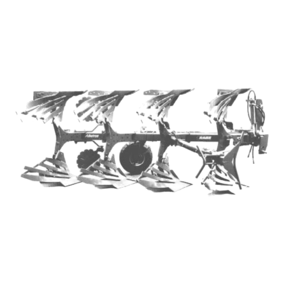
- Page 1 Order-No. 9900.00.01GB01 Operating Instruction Reversible Ploughs Raven (Shearbolt) Raven (Hydro)Avant (Auto-reset)
-
Page 5: For Your Own Safety
For Your Own Safety In this enclosure to the operating instructions you will find some general rules of conduct explaining how to operate the implement correctly - and some safety advice which we advise you to observe for your own safety! The list is very extensive, and some of the advice does not specifically relate to the implement supplied. - Page 6 2. General Safety Advice and Accident Prevention Regulations • Before starting up your implement and tractor, please check that it is roadworthy and operatively safe. • Please observe all generally valid safety and accident prevention regulations. • The warnings and signs found on the implement are there to provide essential data needed to operate the unit safely.
- Page 7 • Road, steering and braking performance will be influenced by mounted or attached implements and ballast. Therefore make sure that you have sufficient steering and brake capability. • Account for the width of the implement and its working load when taking corners. •...
- Page 8 • When using the external controls to operate the three-point linkage, keep clear of the area between the tractor and the implement. • When the implement is in transportation position, always ensure that the tractor’ s three-point linkage is sufficiently locked at the side. •...
- Page 9 • Before engaging the PTO make sure that the area of danger around the implement is free of bystanders. • Never engage the PTO when the engine is switched off. • When working with the PTO, keep the area around the rotating PTO and drive shaft clear of any bystanders.
- Page 10 • Liquids that leak at high pressure (hydraulic oil) can penetrate the skin and cause serious injury! In the event of injury, consult a doctor immediately. Risk of infection! • Before working on hydraulic units, lower the implement, depressurize the system, switch off the engine and remove the ignition key.
- Page 11 • When performing electrical welding work on a tractor with a mounted implement disconnect any cables connected to the generator and the battery. • Gas tanks must only be filled using nitrogen to avoid risk of explosion.! • Spare parts must at a minimum comply with the technical requirements given by the manufacturer of the implement.
- Page 13 Operating instructions Reversible Ploughs Raven, Raven Avant / Hydro-Avant Ensure before operating the plough for the first time that you have thoroughly read and taken note of this operating manual and the safety precautions (”For your own safety”). All persons operating this unit must be properly trained and qualified with regard to use, maintenance and safety requirements, and correctly informed of the hazards involved.
- Page 14 Technical specifications (We reserve the right to make alterations) Underbeam Interbody Furrow Furrows clearance clearance adj. width Plough type ** Weight in standard form kg* ( Tractor max. kW / HP ) (78 / (88 / 32,36,41, Raven 1200 75/80 105) 120) Raven Avant 1200...
- Page 15 Please refer to the appendix entitled ”Pictogram symbols” for an explanation of the warning notices. See Fig.1 (e.g. 3 = numbered series in the explanation) for details of their locations. Replace any missing warning notices. These items can be ordered from RABE as spare parts.
- Page 16 Set-up Ensure that couplings on the three-point linkages are compatible (Cat.: Tractor/Plough). Check tractor tyre pressures and measure the inner clearance between the tyres. This distance should be approximately the same for the front and rear wheels, and the inner walls of the tyres should align (2/1). Set the lower link arms to the same height.
- Page 17 Fi- nal adjustment is then carried out on-site during work. In the RABE adjusting centre, both settings are clearly configured and separately adjusted. Draft: using the turnbuckle (8/1) or adj. sleeve on angling cylinder (7/1) to align the landsides in a paral- lel line to the central turnover shaft (axis of rotation).
- Page 18 Use during operation The lower link arms of the tractor must be able to move sideways during operation. Check chains or stabilisers should be slack. However, they should be laterally rigid when the unit is raised, insofar as this is permitted by the design of the tractor. Working depth: Select ”Draft”...
- Page 19 Draft alignment and front furrow width Adjustments should be carried out in the following order: Draft adjustment first and then the front furrow width. Future adjustments to the front furrow width subject to changing working depths or ploughing on a slope–...
- Page 20 For your owm safety: Use gloves and only suitable tools and spanners (25/3) as provided ! ( RABE part no. 4798.00.99). t is important to observe the torque tensions stated in this manual ( see pages 8, 10 & 12) Skimmers and disc coulters are adjusted at the same time.
- Page 21 Skim coulters There are three ways to adjust the skimmers. Lateral to the plough body by turning the cranked stalk. The clearance in front of the bodies by turning the guide plate around (21/4) and by turning the cranked stalk. The working depth by shifting the skimmer on the stalk up or down.
- Page 22 Shear bolt overload protection All plough models are fitted with shear bolts (25/1). Also the AVANT auto- reset models. The bolt head should always be on the plough leg side. After fitting a new shear bolt, ensure that the other leg pivot bolt is tightened.
- Page 23 Caution: the ”Avant” mechanical auto reset device works under strong spring tension. The built-in compression spring is highly pre – tensioned by the factory. It is very dangerous to dismantle the compression spring without special tools provided by the manufacturer. The spring must only be dismantled by properly qualified technicians using the special tools.
- Page 24 Maintenance Before starting work on the plough attached to the tractor, shut off the engine and remove the ignition key. DO NOT work on a raised plough. ALWAYS lower the plough and release hydraulic pressure before carrying out work on the hydraulic system.
- Page 25 When using shares with bolt – on points reverse the tip first and then move forward. Use ONLY original RABE parts and components and new original bolts and nuts. Tyre pressure: Depth wheel – 2.50 bar Combi –...
- Page 26 400 mm relative to the tractor’s own lighting.) We recommend you to order the required warning notices and lighting systems directly. RABE can also supply bolt-on fixing brackets for DIN 11 027 lighting units.
- Page 27 The pictograms are an integral part of the implement. Warning labels should be visible (dirt-free) at all times, and replaced if damaged – they can be ordered from Rabe under the relevant pictogram number (Pict. No.). Pict. No. Position-No.
- Page 28 Danger of squeezing. Keep away! Rotating tools. Keep away! Do not grasp behind safety devices or covers. Never carry out work unless PTO-drive is disengaged and the engine is stopped. Danger of Life by load from top! Lift Turbodrill only with empty hopper and never together with rotary harrow.
- Page 29 Danger of leg injuries when elements may suddenly swing out. Keep away! Grease all marked grease nipples regulary. The reset force can be increased by adjusting the bolt (kN) to the left (!). Reduce by turning to the right. There must be always a minimum clearance a of 1 mm.
- Page 30 9998.02.85 Hydraulic accumulator is pressurized. Repair and replace only as prescribed in the Technical Manual provided. Oil fl ow path: Forward: ”Lift” 9998.06.01 Oil fl ow path: Return ”Lower” or ””Tank” 9998.06.02 The maximum operating pressure for the hydrau- lic system must not exceed 200 bar! 9998.02.80 The maximum rotational frequency of the PTO max.1000/min...
- Page 31 9998.02.88 Safety catch for road transportation on combi- wheel. Disengage safety catch before working in the fi eld. Technical data subject to change...
Need help?
Do you have a question about the Raven Avant Series and is the answer not in the manual?
Questions and answers