
Related Manuals for Rabe FIELDBIRD


Summary of Contents for Rabe FIELDBIRD
- Page 1 OPERATOR'S MANUAL (ORIGINAL INSTRUCTIONS) Machine number FIELDBIRD Fixed mounted version...
-
Page 3: Quick Start
FiELDBirD uick start FixED mountED vErsion FIELDBIRD quick start Hitching Preparing the tractor Check the pressure of the tyres. Hitch the lower arms. - It must be identical on each side of the tractor, both at the front Attach the top link. -
Page 4: Table Of Contents
Preparation of the implement before work ..20 CE declaration ..........34 Locating the adjustment points ......20 Any use and / or reproduction of all or part of this manual without written authorization from Rabe is strictly prohibited. - 4 - RA_MA_DI_FIELDBIRD_1505_EN - 05/15... -
Page 5: Introduction
FIelDBIrD peratOr s manual FIxeD mOunteD versIOn INTRODUCTION Identification of your equipment 1.4.1 Type plate nstructIons The type plate contains the following information: Product documentation This manual forms an integral part of the implement, and in the event of sale, it must be passed on with the implement in compliance with the applicable regulations. -
Page 6: Safety Instructions And Rules
FIelDBIrD peratOr s manual FIxeD mOunteD versIOn ∙ Connect or disconnect the electrical connections. afety InstructIons and rules ∙ Completely lower the implement to the ground before unhitching it. Make sure that the surface is level and sufficiently firm to ensure that the implement is perfectly stable Safety instructions during storage. - Page 7 FIelDBIrD peratOr s manual FIxeD mOunteD versIOn ∙ When working alone, the operator must be in his cab and ∙ Take all required precautions before leaving the tractor. Apply may never leave his seat. No-one may ride or stand on the the parking brake, stop the engine and take out the ignition implement when it is in operation.
- Page 8 FIelDBIrD peratOr s manual FIxeD mOunteD versIOn 2.1.9 Safety stickers CAUTION: IMPORTANT: Take care not to damage the safety stickers when Replace damaged or missing stickers. washing the implement. Locations of the safety stickers. UI 1829 UI 1829 UI 1834...
- Page 9 FIelDBIrD peratOr s manual FIxeD mOunteD versIOn Explanation of stickers Sticker Description Pivoting zone Remain outside the pivoting zone. UI 1851 Stay outside the working zone Maintain a safe distance from all moving parts. UI 1840 Hooking zone Never work in a zone where there is a risk of crushing while the parts are able to move.
-
Page 10: Description Of The Implement
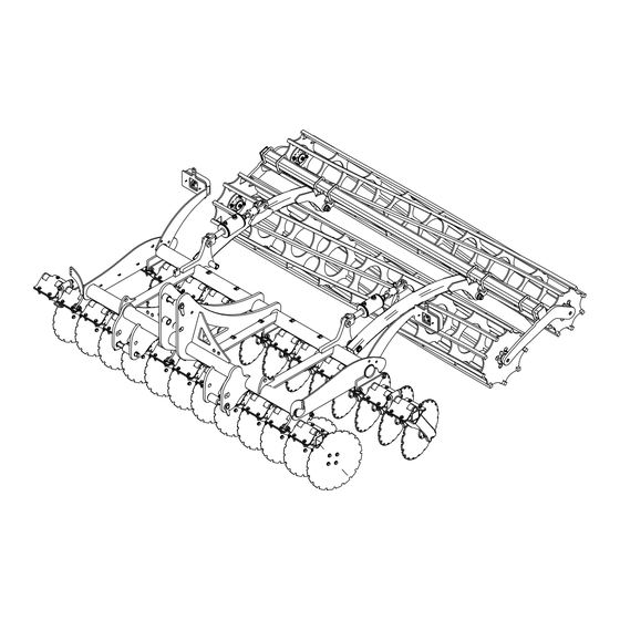
FIelDBIrD peratOr s manual FIxeD mOunteD versIOn escrIptIon of the Implement General views E.g. Normandie 3.00 m double roller and hydraulic option Legend Lower hitch pins Rear roller Ø 420 mm Upper hitch pin Rear roller Ø 500 mm Mulching disc... -
Page 11: Technical Specifications
FIelDBIrD peratOr s manual FIxeD mOunteD versIOn Technical specifications Standard equipment Optional equipment Part ∙ Three-point linkage cat. III, width II with pins locked in rotation. Linkage ∙ Round tube Ø 105 mm. Frame ∙ Disc spacing 250 mm. ∙ Pins locked in rotation. -
Page 12: Loading For Transport
FIelDBIrD peratOr s manual FIxeD mOunteD versIOn 3.4.2 Transport Loading for transport 3.4.1 Hooking points Legend Folded roller Legend Attachment point Frame attachment point IMPORTANT: Check the hooking points according to the configuration (attachments). The hooking points are identified by means of a sticker. -
Page 13: Frame
FIelDBIrD peratOr s manual FIxeD mOunteD versIOn Frame Rear-mounted equipment (options) 3.8.1 Following harrow A sturdy, solid frame consisting of: ∙ Round tubes Ø 105 mm. Legend Following harrow ∙ Reinforced coupling points. The following harrow comprises a row of Ø 12 mm wire tines. - Page 14 FIelDBIrD peratOr s manual FIxeD mOunteD versIOn 3.8.3 Double roller 3.8.5 RIPA roller Legend Legend Double roller RIPA roller The Ø 500 mm front roller comprises nine 25 mm square solid The Ø600 RIPA roller is a rubber roller. bars.
-
Page 15: Lighting And Signals (Standard)
FIelDBIrD peratOr s manual FIxeD mOunteD versIOn 3.8.7 Rear cleaner Lighting and signals (standard) IMPORTANT: IMPORTANT: The rear cleaner is provided as standard with the The user is responsible for ensuring the compliance diamond roller and the packer roller. of the hitched assembly with the applicable regulations for transport on the public highway. -
Page 16: Preparing The Tractor
FIelDBIrD peratOr s manual FIxeD mOunteD versIOn reparIng the tractor Required tractive power The power required to tow your implement varies according to the soil texture, the working conditions and the tractor equipment (tyres, front ballast, etc.). The following technical specifications are provided as a guide. -
Page 17: Length Of The Lifting Links
FIelDBIrD peratOr s manual FIxeD mOunteD versIOn Length of the lifting links Position of the stabilisers Legend Legend Raised position Operating clearance Lowered position Pins Tie rod The length of the link arms determines the balance of the hitch and the position of the lifting cylinders while working (ensures symmetrical working between left- and right-hand sides). -
Page 18: Top Link
FIelDBIrD peratOr s manual FIxeD mOunteD versIOn ItchIng and unhItchIng Top link. Hitching the implement to the tractor CAUTION: Make sure that hitching the implement does not result in: - Overloading: Observe the maximum permissible load at the hitching points. -
Page 19: Unhitching The Implement From The Tractor
FIelDBIrD peratOr s manual FIxeD mOunteD versIOn CAUTION: Unhitching the implement from the Before proceeding to connect the top link, make tractor sure the space between the implement yoke and the lower arms of the tractor is sufficient, so that... -
Page 20: Preparation Of The Implement Before Work
FIelDBIrD peratOr s manual FIxeD mOunteD versIOn reparatIon of the Implement before work Locating the adjustment points ∙ Locate the various adjustment points. ∙ Make sure that they are functioning properly and that they are well lubricated. Perform the checks before setting out for the field. -
Page 21: Hydraulic Connections (Optional)
FIelDBIrD peratOr s manual FIxeD mOunteD versIOn hydraulIc connectIons hangIng between optIonal transport and workIng posItIon Required hydraulic control valve Changing to transport position ∙ 1 Double-acting (DA) valve for hydraulic adjustment of roller(s). Before driving on a public road: ∙... -
Page 22: Changing To Working Position
FIelDBIrD peratOr s manual FIxeD mOunteD versIOn Procedure Changing to working position ∙ Lower the implement. ∙ Unfold the outer discs. ∙ Connect the top link into the fixed hole, the implement is now ready for work. 8.2.1 Unfolding retractable discs... -
Page 23: Driving On The Road
FIelDBIrD peratOr s manual FIxeD mOunteD versIOn Ield adjustment Driving on the road CAUTION: CAUTION: Read this chapter in its entirety to properly Take account of the overhang when driving on the understand all adjustments, the correct order and public highway. Risk of accidents involving other procedures before starting work. - Page 24 FIelDBIrD peratOr s manual FIxeD mOunteD versIOn 9.1.4 Roller working depth indicator Legend End stop Legend Release latch Indicator Operating arm Sticker support Release latch ∙ To increase the working depth, raise the roller: - Unscrew the end stop (1).
-
Page 25: Use In The Field
FIelDBIrD peratOr s manual FIxeD mOunteD versIOn Use in the field ∙ Place the implement in the working position (see 8.2). IMPORTANT: For an optimum result, the working speed must be between 10 and 12 km/h (5 and 6 mph). A higher speed may cause rapid wear of the working parts. - Page 26 FIelDBIrD peratOr s manual FIxeD mOunteD versIOn 9.3.2 Lateral levelling 90° In the working position, the frame of the implement must be level from left to right. This normally occurs when: ∙ tractor preparation has been carefully carried out: ∙ the tyre pressures are identical on both sides, the link arm stabilisation devices are installed, the tractor linkage vertical alignment is correctly adjusted.
-
Page 27: Front Disc Gang Offset
FIelDBIrD peratOr s manual FIxeD mOunteD versIOn Position of gangs before offsetting Front disc gang offset IMPORTANT: Only offset the front gang. Legend Front gang Rear gang Position of gangs after offsetting Legend Front disc gang Rear disc gang ∙ The front disc gang (1) can be offset to compensate for disc wear. -
Page 28: Disc Overlap Adjustment Spacers
FIelDBIrD peratOr s manual FIxeD mOunteD versIOn Mounting of Ø 460 mm discs with 2 x 20 mm spacers. Disc overlap adjustment spacers The implement can be fitted with adjustment spacers to ensure good overlap between the front and rear disc gangs as the discs wear. -
Page 29: Maintenance
FieLDBiRD aintenance FixeD MounteD veRsion 11 c MAINTENANCE leanIng CAUTION: Clean the implement. Observe the safety instructions (see Chap. 2) before ∙ When cleaning with a high pressure cleaner, do not direct the starting service work or replacing spare parts. - Page 30 FieLDBiRD aintenance FixeD MounteD veRsion ∙ Check that couplings, components, etc. are securely tightened. ∙ Drain the implement if you need to replace components in the hydraulic circuit. CAUTION: Never open, pierce, weld or perform work on the hydraulic reservoirs.
-
Page 31: 12.2 Lubrication And Greasing
FieLDBiRD aintenance FixeD MounteD veRsion 12.2 Lubrication and greasing Location of lubricating nipples IMPORTANT: The location of lubrication nipples depends on the various assemblies and options of your implement. IMPORTANT: Check the location of lubrication nipples using the spare parts catalogue supplied with your implement. -
Page 32: Spare Parts
FieLDBiRD aintenance FixeD MounteD veRsion 13 s pare parts In order to ensure the reliable operation and long service life of your implement, only use original spare parts from the manufacturer. The use of any parts, other than those provided by the manufacturer automatically voids the warranty. -
Page 33: 13.3 Precautions For Storage
FieLDBiRD aintenance FixeD MounteD veRsion 13.3 Precautions for storage CAUTION: Never allow children to play around an implement if it is hitched to a tractor or in its storage area. DANGER: Never store agricultural machinery under a power line. ∙ Before unhitching implement for storage, make sure the storage area is level, clean and firm. -
Page 34: Ce Declaration
dEClaration 14 ce declaratIon EC Declaration of Conformity (Directive Machinery 2006/42/CE, Appendix II, point A) Manufacturer: Grégoire Besson Address: rue Victor Grégoire, 49230 Montfaucon - Montigné Name of the person authorized to compile the technical specifications: P. Besson Adress: rue Victor Grégoire, 49230 Montfaucon - Montigné Herewith declares that: The machine: Réversible portée légère... - Page 36 RABE ZI Nord Les Gaudères 37130 Langeais France Tel. (+33) 2 47 96 72 61 Fax (+33) 2 47 96 71 85 souchu@gregoirebesson.fr www.souchu.eu RABE Am Rabewerk 1 49152 Bad Essen Germany Tel. +49 (0) 54 72 771 - 0 Fax +49 (0) 54 72 771 -195 info@rabe-agri.eu...
Need help?
Do you have a question about the FIELDBIRD and is the answer not in the manual?
Questions and answers