
Related Manuals for Fac F300 VO


Summary of Contents for Fac F300 VO
- Page 1 Fabbrica Affettatrici Cavaria Use and maintenance manual *403.250 - *403.300 MADE IN ITALY 403250-300 en ma 2017...
-
Page 2: Table Of Contents
CONTENTS - TECHNICAL SPECIFICATIONS ................... page 3 ------------------------------------------------------------------- - OVERALL SIZE .......................” ------------------------------------------------------------------- 1.1 - PURPOSE OF USER GUIDE ................” 1.2 - USER GUIDE CONSULTATION AND STORAGE ...........” 1.3 - USER WARNINGS ....................” 1.4 - USING THE SLICER CORRECTLY ...............” 1.5 - MANUFACTURER’S WARRANTY AND LIABILITY ..........”... -
Page 3: Technical Specifications
TECHNICAL SPECIFICATIONS • Blade diameter ........mm • Slice thickness ........mm 0 ÷ 2,5 (9 position) • Effective slice - Length ........... mm - Height............ mm • Product holder stroke ......mm • Weight - Slicer ............kg 45,5 - Stand (optional)........ -
Page 4: Overall Size
OVERALL SIZE 340mm 400mm 720mm 600mm 400mm 500mm 650mm 403250-300 en ma 2017... -
Page 5: Purpose Of User Guide
Keep this guide in a safe place for • This publication contains all information further consultation. necessary for the installation use and maintenance of F300 VO flywheel • This guide MUST be kept throughout the slicers. life of the slicer and if necessary (e.g. -
Page 6: User Warnings
1.3 - USER WARNINGS • Check the slicer’s mechanical integrity Use of the machine requires great prior to every use. concentration, PAY ATTENTION AT Components should show no signs of ALL TIMES! damage or cracks. If this is not the case, DO NOT use the •... -
Page 7: Using The Slicer Correctly
1.4 - USING THE SLICER CORRECTLY • The product to be sliced should only be • The slicer is only designed to slice food placed on and removed from the feed of the type and size specified herein. carriage when the latter is fully retracted (furthest away from the blade) and the The manufacturer shall accept no carriage nearest the operator. -
Page 8: Manufacturer'swarranty And Liability
1.5 - MANUFACTURER’S 1.6 - IDENTIFYING THE SLICER WARRANTY AND LIABILITY • The slicer mentioned in this instruction • The slicer described herein is covered by booklet is designed and manufactured a warranty as specified in the enclosed according to current EU standards certificate. -
Page 9: Unpacking
1.7 - UNPACKING • Should any faults be noted, such as: • When taking delivery of the slicer, ensure - dents to the frame or guards; that the packaging is fully intact; if this is - controls that are either not working or not the case, please advise the courier broken;... -
Page 10: Description Of The Slicer
D O N O T D U M P PA C K A G I N G ! In any event, it is preferable to sort DISPOSE OF WASTE RESPONSIBLY! products prior to disposal in accordance with current recycling regulations. 2.1 - DESCRIPTION OF THE SLICER 12. - Page 11 Fig.3 - Description of components 403250-300 en ma 2017...
-
Page 12: Installing The Slicer
3.1 - INSTALLING THE SLICER • Position the slicer in its allocated Positioning the slicer (fig. 5) workplace. • If not using the optional stand, carefully lift the slicer and position on a level Use of stand (optional) (fig. 4) surface (fig. -
Page 13: Fitting The Flywheel And Operating Handle
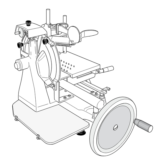
3.2 - FITTING THE FLYWHEEL AND OPERATING HANDLE In order to facilitate transport, the operating handle (6) is delivered unattached to the slicer, • Insert the flywheel (7) so that the whilst the flywheel (7) may also be removed operating handle (6) fixing hole (x) is in order to facilitate transport and/or packing. - Page 14 • Use a hammer to insert the taper pin (30) • Screw pin (35) complete with nut (36) fully. onto flywheel (7); tighten nut (36). Fig. 9 Fig. 10a • Tighten the screw (7a). • Insert handle (6) in pin (35) and tighten screw (37).
-
Page 15: Description Of Controls
3.3 - DESCRIPTION OF CONTROLS Flywheel Sliding product holder operating knob Clockwise rotation of the flywheel (7) The knob (12) allows you move the using the handle (6) will move the product holder (4) towards or away from carriage (5) with product holder (4), the blade (16). - Page 16 Sliding product holder fast forward lever Pusher vertical slide lever By lowering and holding in position the By keeping pressed the lever (10) you lever (11) you can quickly move the can quickly raise or lower the pusher (3). product holder (4) towards or away from the blade (16) (with product).
-
Page 17: Using The Slicer
4.1 - USING THE SLICER WARNING: • Move the product holder (4) away as • DO NOT use the slicer if not fully far as its limit of travel (furthest from the physically and mentally fit. blade) using either the knob (12) or the fast forward lever (11). -
Page 18: Slicing The Product
4.3 - SLICING THE PRODUCT Failure to hold the product firmly in place on the product holder could cause the • Move the blade guard (9) to the left by machine to cut uneven slices. loosening the knob (9a). • Turn the knob (13) in order to set the required slice thickness. - Page 19 Fig. 17 DO NOT turn the flywheel (7) • You should stop turning the flywheel anticlockwise. (7) once the operation is complete; the Serious damage to the slicer could blade will halt its movement (16). be caused. • Move the product holder (4) (with the •...
- Page 20 • Reposition the blade guard (9) by • Press the lever (10) and lift the pusher tightening the knob (9a) (fig. 19). (3). • Remove the product from the table (4). WARNING: Do not leave the slicer without the blade guard (9) in the correct position.
-
Page 21: Cleaning The Slicer
5.1 - CLEANING THE SLICER The slicer SHOULD be cleaned • Unscrew knob (34) and lift the sliding thoroughly at least once a day and product holder (4) complete with pusher more frequently where necessary. arm (3). Clean the slicer before use if it has been out of service for some time. -
Page 22: Cleaning The Blade
• Rinse in hot water only and dry with soft • Secure the product holder (4) to the spongy cloths. carriage (5) by tightening the knob (34). WARNING: 5.2 - CLEANING THE BLADE DO NOT clean the machine with water jets, steam or similar methods or in dishwashers using corrosive WARNING: detergents. -
Page 23: Cleaning The Blade Cover
5.4 - CLEANING THE SLICE 5.3 - CLEANING THE BLADE COVER RECEIVING SURFACE WARNING: • Remove the slice receiving surface (1) Cutting hazard! Use protective cut- by loosening the two screws (1a) and and tear-resistant gloves and perform releasing from the retaining clips (1b). all operations with extreme care. -
Page 24: Routine Maintenance
6.1 - ROUTINE MAINTENANCE In addition to the above-mentioned cleaning operations, you should also perform routine Being particularly complicated and hazardous maintenance in order to guarantee the for the operator, other maintenance slicer’s operating efficiency over time. operations SHOULD only be performed by staff from an authorised service centre. -
Page 25: Oiling Carriage Guide Rail And Product Holder And Lubrication Points
6.2 - OILING CARRIAGE GUIDE RAIL AND PRODUCT HOLDER AND LUBRICATION POINTS Do not use vegetable oil. • Apply a few drops of lubricant (maximum • Every week you should oil the carriage 3 or 4) to the guide rails and slide the (5) and product holder (4) guide rails (36) assemblies back and forth 3/4 times. - Page 26 • Also oil the catch (10) of the pusher’s (3) • Slide the pusher (3) back and forth 3/4 vertically sliding lever. times. • Apply 2/3 drops of lubricant. • Wipe excess lubricant with a paper towel. Fig. 28 403250-300 en ma 2017...
-
Page 27: Blade Sharpening
6.3 - BLADE SHARPENING Proceed as follows: WARNING: • Move the product holder (4) away as Cutting hazard! far as its limit of travel (furthest from the Use protective cut- and tear-resistant blade) using either the knob (12) or the gloves and perform all operations fast forward lever (11). - Page 28 • Loosen the knob (38) holding the sharpener (17) in place (fig. 31). • Lift the sharpener (17) and turn 180° (fig. 32). • Carefully lower the sharpener (17) again, the blade (16) will automatically be centred between the two grinding wheels (fig.
- Page 29 • Turn the flywheel (7) whilst pressing For safety reasons do not exceed 1 or the “X” button and perform about 20/30 2 blade revolutions in order to prevent blade revolutions. the blade edge from springing back. • Stop rotation and use a pencil to check that a slight burr has formed on the blade •...
-
Page 30: Oiling Chain And Bevel Gear
6.4 - OILING CHAIN AND BEVEL GEAR Every 6 months proceed as follows: Use the lubricant sparingly. • Lift the slicer and apply 3/4 drops of the supplied lubricant to the chain (19) and • Wipe excess lubricant with a paper gears (20). - Page 31 7.1 - TAKING THE SLICER OUT OF SERVICE WARNING: A machine comprises: ALWAYS consult the manufacturer or • Aluminium-alloy frame. authorised service staff as regards • Stainless-steel inserts and components. removal and disposal of the blade • Plastics, etc. (16) so that this can take place in complete safety.
-
Page 32: Troubleshooting
8.1 - TROUBLESHOOTING PROBLEM PROBABLE CAUSE SOLUTION • Difficulty in slicing; • The blade is blunt. • Sharpen the blade. excessive resistance • Product is overly mature • Tenderise product when the product is in or too dry. before slicing. contact with the blade. -
Page 33: Spares
Spare parts 403250-300 en ma 2017... - Page 34 Fig. 1 BASAMENTO BASE Ed. 05/2012 403250-300 en ma 2017...
- Page 35 Fig. 2 GUIDE CARRIAGE GUIDE RAILS Ed. 05/2012 403250-300 en ma 2017...
- Page 36 Fig. 3 LAMA HOJA BLADE Ed. 05/2012 403250-300 en ma 2017...
- Page 37 Fig. 4 CARRELLO CARRO CARRIAGE Ed. 05/2012 403250-300 en ma 2017...
- Page 38 Fig. 5 AVVICINAMENTO RAPIDO REGULACIÓN DEL ESPESOR THICKNESS CONTROL Ed. 05/2012 403250-300 en ma 2017...
- Page 39 Fig. 6 REGOLAZIONE SPESSORE VOLANO FLYWHEEL Ed. 05/2012 19 18 403250-300 en ma 2017...
- Page 40 Fig. 7 PRESSAMERCE PRODUCT HOLDER PORTAFIAMBRES Ed. 05/2012 403250-300 en ma 2017...
- Page 41 Fig. 8 AFFILATOIO AFILADERA SHARPENER Ed. 05/2012 403250-300 en ma 2017...
-
Page 42: Guide To The Treatment Of Waste Equipment
GUIDE TO THE TREATMENT OF WASTE EQUIPMENT Disposal This product complied with Directive Manufacturers and/or importers fulfil their 2002/19/UE. obligations concerning environmentally- compatible recycling, treatment and disposal either directly or by joining a collective scheme. The crossed out wheeled bin symbol on equipment indicates that it must be treated separately from household waste at the end of its working life and therefore...
Need help?
Do you have a question about the F300 VO and is the answer not in the manual?
Questions and answers