Table of Contents
Advertisement
Quick Links
MAN0886-03-EN
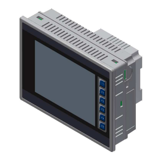
XL6/XL6e OCS Models
HE-XL103 / HEXT350C113
HE-XL1E3 / HEXT351C113
Digital DC Inputs / 12 Digital Outputs
2 Analog Inputs (Medium Resolution)
1
Specifications
Digital DC Inputs
Inputs per Module
Commons per Module
Input Voltage Range
Absolute Max. Voltage
Input Impedance
Input Current
Upper Threshold
Lower Threshold
Max Upper Threshold
Min Lower Threshold
OFF to ON Response
ON to OFF Response
HSC Max. Switching Rate
Analog Inputs, Medium
Resolution
Number of Channels
Input Ranges
Safe input voltage range
Input Impedance
(Clamped @ -0.5 VDC to 12
VDC)
Nominal Resolution
%AI full scale
Max. Over-Current
Conversion Speed
Max. Error at 25°C (excluding
zero)
Additional error for temperatures
other than 25°C
Filtering
Serial Ports
Ethernet
USB
Removable Media
Smartstix
__________________________________________________________________________________________________________________________________________________________________
4/28/2009
XL103
12 including 4
24 including 4
configurable HSC inputs
configurable HSC inputs
1
12 VDC / 24 VDC
35 VDC Max.
10 kΩ
Positive Logic
Negative Logic
0.8 mA
0.3 mA
8 VDC
3 VDC
1 ms
1 ms
10 kHz Totalizer/Pulse,Edges
5 kHz Frequency/Pulse,Width
2.5 kHz Quadrature
XL103
2
0 - 10 VDC
0 – 20 mA
4 – 20 mA
-0.5 V to +12V
Current Mode:
100 Ω
Voltage Mode:
500 k Ω
10 Bits
32,000 counts
35 mA
All channels converted once per ladder scan
4-20 mA
1.00%
0-20 mA
1.00%
0-10 VDC
0.50%
TBD
160 Hz hash (noise) filter
1-128 scan digital running average filter
USB Networking Port for communication with PCs and programming Port
Removable Media for upto 2 GB of storage for programs, data logging or screen capture
Note: Highest usable frequency for PWM output is 65 KHz
XL6/XL6e OCS Models
24 Digital DC Inputs / 16 Digital Outputs
Specifications
XL104
Digital DC Outputs
Outputs per Module
Commons per Module
Output Type
Absolute Max. Voltage
Output Protection
Max. Output Current
per point
-1.6 mA
Max. Total Current
Max. Output Supply
-2.1 mA
Voltage
Minimum Output Supply
Voltage
Max. Voltage Drop at
Rated Current
Max. Inrush Current
Min. Load
OFF to ON Response
XL104
ON to OFF Response
2
Output Characteristics
Required Power
(Steady State)
Required Power (Inrush)
Primary Power Range
Relative Humidity
Operating Temperature
Terminal Type
CE
UL
Clock Accuracy
Connectivity
2 Serial Ports – RS232 & RS485
10/100-Mbps (XL6e models only)
Remote IO modules communicating on CAN
Page 1 of 6
HE-XL104 / HEXT350C114
HE-XL1E4 / HEXT351C114
2 Analog Inputs (Medium Resolution)
XL103
12 including 2 configurable
PWM outputs
Sourcing / 10 K Pull-Down
28 VDC Max.
Short Circuit
4 A Continuous
0.25 VDC
650 mA per channel
Current Sourcing (Pos logic)
General Specifications
30 A for 1 ms @ 24 VDC – DC Switched
2.5 A for 4 ms @ 24 VDC - AC Switched
5 to 95% Non-condensing
Screw Type,5 mm Removable
See Compliance Table at
http://www.heapg.com/Pages/TechSupport/ProductCert.html
Weight
+/- 35 ppm maximum at 25° C
(+/- 1.53 Minutes per Month)
Specifications / Installation
XL104
16 including 2 configurable
PWM outputs
1
0.5 A
30 VDC
10 VDC
None
1 ms
1 ms
500 mA @ 24 VDC
10 – 30 VDC
-10°C to +60°C
26.5 oz. (.751 kg)
ECN # 950
Advertisement
Table of Contents

Subscribe to Our Youtube Channel
Related Manuals for HORNER XL6 Series


Summary of Contents for HORNER XL6 Series
- Page 1 MAN0886-03-EN Specifications / Installation XL6/XL6e OCS Models XL6/XL6e OCS Models HE-XL103 / HEXT350C113 HE-XL104 / HEXT350C114 HE-XL1E3 / HEXT351C113 HE-XL1E4 / HEXT351C114 Digital DC Inputs / 12 Digital Outputs 24 Digital DC Inputs / 16 Digital Outputs 2 Analog Inputs (Medium Resolution) 2 Analog Inputs (Medium Resolution) Specifications Specifications...
- Page 2 Installation Panel Cut-Out and Dimensions Prior to mounting, observe requirements for the panel layout design and spacing/clearances in the OCS XL6 Series Manual Note: Max. panel thickness: 5 mm. (MAN0883). Refer to the XL6 User Manual (MAN0883) for panel box information and a handy checklist of 2.
- Page 3 Memory Slot: Uses Removable Memory for data logging, screen captures, program loading and recipes. Horner Part No.: HE-MC1 Serial Communications: MJ1: (RS-232 / RS-485) Used for Cscape programming and Application- Defined Communications. MJ2: (RS-232 / RS-485) Used for Application-Defined Communications.
- Page 4 MAN0886-03-EN Specifications / Installation Serial Communications: MJ2 Pinouts in Half and Full Duplex Modes MJ1: (RS-232 / RS-485) Use for Cscape programming MJ2 Pins and Application-Defined Communications. Signal Direction MJ2: (RS-232 / RS-485) Use for Application-Defined Communications. Ground MJ1 Pins MJ2 Pins +5 60mA Signal...
- Page 5 MAN0886-03-EN Specifications / Installation Power Port and Wiring Wiring Examples XL103 / 104 J1 Orange Positive Logic Digital In XL103 / XL104 Orange Name 12-24VDC Primary Power Port Pins Signal Description HSC1 / IN9 Ground Frame Ground HSC2 / IN10 Note: HSC3 / IN11 Input Power Supply Ground...
- Page 6 Email: techsppt@heapg.com Email: tech.support@horner-apg.com No part of this publication may be reproduced without the prior agreement and written permission of Horner APG, Inc. Information in this document is subject to change without notice. __________________________________________________________________________________________________________________________________________________________________ 4/28/2009 Page 6 of 6...
Need help?
Do you have a question about the XL6 Series and is the answer not in the manual?
Questions and answers