Table of Contents
Advertisement
Quick Links
alféa hybrid duo
Water/air heat pump
with integrated fuel oil burner,
single phase or three phase
split, 2 services
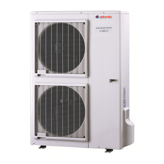
Outdoor unit
AOYA 30 LBTL
AOYA 45 LBTL
AOY 54 LJBYL
WOYK112LCT
WOYK140LCT
WOYK160LCT
alféa hybrid duo 10
alféa hybrid duo 13
alféa hybrid duo 16
alféa hybrid duo 11 Tri
alféa hybrid duo 14 Tri
alféa hybrid duo 16 Tri
Hydraulic module
024101
Document n° 1440-13 ~ 20/12/2012
Document n° 1440-11 ~ 29/08/2012
FR
ES
PT
IT
FI
SE
Installation and
commissioning
instructions
for professionals
To be kept by the user
for future reference
atlantic-comfort.com
The specifications of this equipment may
be modified without prior instructions
Non-contractual document.
EN
Advertisement
Table of Contents

Related Manuals for Atlantic Alfea Hybrid Duo Series


Summary of Contents for Atlantic Alfea Hybrid Duo Series
- Page 1 11 Tri alféa hybrid duo 14 Tri Installation and alféa hybrid duo 16 Tri commissioning instructions for professionals To be kept by the user for future reference atlantic-comfort.com The specifications of this equipment may be modified without prior instructions Non-contractual document.
-
Page 2: Table Of Contents
Heat pump alfea hybrid duo Thank you for buying this product. ISO 9001 certified, the industrial heating company, part of the Atlantic group, guarantees the quality of its appliances and undertakes to satisfy the requirements of its customers. The experience and expertise of the company is associated to leading edge technologies in the design and manufacture of its range of heating appliances. - Page 3 Heat pump alfea hybrid duo " The following are required for the installation of this appliance: - qualified personnel, certified as capable of handling refrigerating fluids (in compliance with article R543.106 of the environmental code), - a heating engineer . Regulation .
-
Page 4: Presentation Of The Equipment
Heat pump alfea hybrid duo 1 Presentation of the equipment 1 .1 Packaging • 1 box: Outdoor unit. • 1 box: Hydraulic module with burner and outdoor temperature sensor. Pairing table Heat pump Heat pump Outdoor unit Outdoor unit Hydraulic module hybrid duo Hydraulic module hybrid duo Model Export code... - Page 5 Heat pump alfea hybrid duo Denomination of model ..alféa hybrid duo ..10 ..13 ..16 ..11 tri ..14 tri ..16 tri Absorbed power +7°C/+35°C - under-floor heating .
- Page 6 Heat pump alfea hybrid duo " Outdoor unit, hybrid duo 10 model Drain hole (Ø 20) 4 holes (Ø 10) Bottom view 3/8" 5/8" Front view Side view Top view " Outdoor unit, hybrid duo 13 model, hybrid duo 16 model Drain hole (Ø...
- Page 7 Heat pump alfea hybrid duo " Outdoor unit, model hybrid duo 11 tri, model hybrid duo 14 tri, model hybrid duo 16 tri holes Drain hole (ø 10) (ø 20) Bottom view 1290 Front view Side view Top view figure 2 - Dimensions in mm "...
- Page 8 Heat pump alfea hybrid duo Outdoor sensor QAC34 43907 10000 2490 1000 ° C Heat pump return sensor Heat pump start sensor 32500 30000 figure 7 - Pressure drop in the combustion circuit 27500 25000 22500 1 mbar = 10 mmCE = 100 Pa mbar 20000 17500...
-
Page 9: Description
Heat pump alfea hybrid duo 1 .6 Description " model hybrid duo 10 " model hybrid duo 13, hybrid duo 16 Legend 1 - High performance impeller and low noise level 2 - Electrical motor with variable "inverter" " model hybrid duo 11 tri, hybrid duo 14 tri, operation hybrid duo 16 tri 3 - "Inverter"... - Page 10 Heat pump alfea hybrid duo Legend Condenser 13 domestic hot water circulation 24 Domestic hot water sensor pump "Liquid" refrigerating connector Control panel 14 Drain valve "gas" refrigerating connector 25 User interface 15 Safety valve Combustion chamber 26 Reset button 16 Manual drain tap Chamber door (overheating safety device)
-
Page 11: Operating Principle
Heat pump alfea hybrid duo 1 .7 Operating principle The heat pump transmits the energy in the outdoor air • Regulation functions to the home to be heated. - The initial temperature of the heating circuit is The heat pump is formed of four main elements inside controlled by water logic. - Page 12 Heat pump alfea hybrid duo • Operating principle of the domestic hot water Increase in temperature of the tank (without drawing) (DHW) Two domestic hot water (DHW) temperatures can °C be set: comfort temperature (line 1610 at 65°C) and reduced temperature (line 1612 at 40°C). The default DHW programme (line 560, 561, 562, 563 and 564) is set for a comfort temperature from 0h00 to 5h00 and from 15h00 to 18h00 and a reduced...
-
Page 13: Installation
Heat pump alfea hybrid duo 2 Installation 2 .1 Statutory conditions 2 .3 .3 Containment of refrigerant circuits for installation and servicing All refrigerant circuits fear contamination from dust and moisture. If such pollutants introduced into refrigeration The appliance must be installed and the maintained circuit, they can contribute to degrade the reliability of by an approved professional in accordance with the the heat pump... -
Page 14: Installing The Outdoor Unit
Heat pump alfea hybrid duo 2 .5 Installing the outdoor unit 2 .5 .1 Installation precautions " The outdoor unit must only be installed outdoors. If a shelter is required, it must have large apertures on all 4 sides and respect the space required for the installation (figure 15 H >... -
Page 15: Connection Of The Condensate Evacuation Pipe
Heat pump alfea hybrid duo 2 .5 .3 Connection of the condensate evacuation pipe If an evacuation pipe must be used: " If installed in a region where the temperature may be below 0°C for a long period, the evacuation - Use the elbow provided (C) and connect a flexible pipe must have a resistance tracer to avoid it hose of 16 mm diameter to evacuate the condensates. - Page 16 Heat pump alfea hybrid duo 150 mm Minimum 1000 mm 1000 mm ou plus ou plus Minimum 1500 mm 1000 mm 300 mm 500 mm Max. 500 mm Max. 500 mm 500 mm 300 mm 1500 mm ou plus Minimum 1500 mm ou plus Minimum 1500 mm...
-
Page 17: Installing The Hydraulic Module
Heat pump alfea hybrid duo 2 .6 Installing the hydraulic module 2 .6 .1 Requirements of installation space The room where the appliance operates must respect the regulations in force. 300 mm The appliance must be installed in a suitable and well ventilated room. -
Page 18: Connection Pipe
Heat pump alfea hybrid duo 2 .6 .3 Connection pipe • Brazing on the refrigerating circuit The evacuation pipe must comply with the regulations (if required) in force. - Silver brazing (40% minimum recommended). The cross section of the connection pipe must not be smaller than the outlet nozzle of the appliance. -
Page 19: Refrigerating Connections
Heat pump alfea hybrid duo 2 .7 .2 Refrigerating connections 2 .7 .5 Connecting the flare connections The connection between the outdoor unit and the " The small tube must always be connected hydraulic module using only copper connections before the large one . (refrigerating grade), must be insulated separately. - Page 20 Heat pump alfea hybrid duo Refrigerating Outdoor unit connectors Diameter of refrigerating Hydraulic module connections connections connectors 5/8" (D1) 5/8" 5/8" liquid 3/8" (D2) 3/8" 3/8" Outdoor unit Hydraulic Module Unité module hydraulique extérieure Liquid valve Vanne “liquide” Flare nut Écrou flare "Liquid"...
-
Page 21: Commissioning Of The Refrigerating Gas Installation
Heat pump alfea hybrid duo 2 .8 Commissioning of the refrigerating gas installation ANNEX 2 " This operation is reserved for installers familiar Method 3 empty with the legislation for handling refrigerants . - Connect the high pressure hose to the Manifold, "... -
Page 22: Sealing Test
Heat pump alfea hybrid duo • First seal test Refrigeration connecxion (Gas) Refrigeration connexion - Remove the protective plugs (B) from the charging hole (Schrader) in the "Gas" valve (large diameter). Plug (A) - Connect the high pressure hose to the Manifold 3-way valve - Connect the bottle of nitrogen to the Manifold (Use only dry nitrogen type U) -
Page 23: Additional Charge
Heat pump alfea hybrid duo model hybrid duo 10 single phase 40 g of R410A per extra m length of connection 15 m 25 m Additional charge none 400 g model hybrid duo 13 single phase 50 g of R410A per extra m length of connection 15 m 25 m... -
Page 24: Collect The Refrigerating Fluid
Heat pump alfea hybrid duo 2 .9 Hydraulic connection 2 .8 .4 Collect the refrigerating fluid in the outdoor unit 2 .9 .1 General " Only for the three phase models The connection must comply with trade practices Carry out the following procedures to collect the according to the regulations in force. -
Page 25: Connection To The Domestic Circuit
Heat pump alfea hybrid duo 2 .9 .2 Connection to the domestic circuit Place a safety group with a valve calibrated to 7 bar on the cold water inlet, and connect an evacuation pipe leading to the drain To allow the tank to be emptied by siphoning, the safety unit must be placed at a lower level than the cold water inlet It is recommended that the hot water outlet is fitted with... -
Page 26: Filling And Draining The Installation
Heat pump alfea hybrid duo 2 .10 Connection of the fuel supply 2 .9 .5 Filling and draining the installation " Compulsory! Fill and pressurise the domestic Refer to the instructions supplied with the burner. tank before filling the heater with water. In order for the burner to operate correctly, a filter The warranty of the appliance will not apply if (60 μm) must be installed on the fuel supply pipe. -
Page 27: Electrical Connections
Heat pump alfea hybrid duo 2 .11 Electrical connections Before carrying out any work, ensure that the general electrical power supply is switched off. 2 .11 .1 Characteristics of the electrical power supply electrical installation must comply with the regulations in force. The electrical connections will only be made when all of the other assembly operations (attachment, assembly,...) have been carried out. -
Page 28: Overall View Of The Electrical Connections
Heat pump alfea hybrid duo 2 .11 .3 Overall view of the electrical connections The electrical diagram of the hydraulic module is detailed in figure 60, page 60 radio central ambient unit T78 (option) Outdoor sensor: cable 2 x 0.75 mm² Central ambient unit T75 (optional): Connection of outdoor unit, hydraulic module: cable 3 x 0.5 mm²... -
Page 29: Electrical Connections On Outdoor Unit Side For Single Phase Model
Heat pump alfea hybrid duo 2 .11 .5 Electrical connections on outdoor unit side for single phase model Access to the connector terminals - Remove the front panel, remove the cover. - Make the connections in compliance with the diagram Te r m i n a l (figure 45, page 31). -
Page 30: Electrical Connections On The Outdoor Unit Side For The Three Phase Model
Heat pump alfea hybrid duo - Use the cable clamps to avoid any accidental Cables disconnection of the conductive wires. - Obstruct the space at the cable inlet in the outdoor unit with the insulating plate. space required "Gas" valve figure 38 - Viewing the difference between the "gas"... -
Page 31: Electrical Connections On The Hydraulic Module Side
Heat pump alfea hybrid duo 2 .11 .7 Electrical connections on the hydraulic module side Grommets (power) Terminal blocks Grommet (sensors) Heat pump regulator Interface board figure 43 - Access to the electrical cabinet and the hydraulic module and description Access to the connector terminals •... - Page 32 Heat pump alfea hybrid duo " Single phase model Inter-connection between outdoor unit Electrical and hydraulic module power supply burner 230 V green/yellow blue brown Outdoor unit single phase Hydraulic module " Three phase model Outdoor unit three phase burner green/yellow 1 2 3 L1 L2 L3 N blue...
- Page 33 Heat pump alfea hybrid duo Information contact Load shedding or EJP for the HP/HC meter * (Delete peak rate day) *If the command does not supply a potential free contact, the contact must be relayed to obtain equivalent wiring. In all cases, refer to the instructions for the external parts (load shedder, energy meters…) for the wiring.
-
Page 34: Outdoor Sensor
Heat pump alfea hybrid duo 2 .12 Outdoor sensor 2 .13 Ambient sensor and/or central ambient unit(radio) The Outdoor sensor is required for the correct operation of the heat pump. The ambient sensor (or the central ambient unit) is optional Consult the assembly instructions on the packaging of the sensor. -
Page 35: Verifications And Commissioning
Heat pump alfea hybrid duo 2 .14 Verifications and commissioning " If the installation is equipped with under-floor • Carry out the usual verifications of the burner and its heating: It is essential to set the parameters 741 energy power circuit. and/or 1041 (page 42 and/or... -
Page 36: Adjusting The Burner
Heat pump alfea hybrid duo 2 .15 Adjusting the burner 2 .16 Configuration of the ambient sensor Refer to the instructions supplied with the burner. T55 - To configure the ambient sensor and associate it Stella 4000 unit burner to the adequate heating zone: Fuel flow rate, - Press for more than 3s the presence button Pump pressure... - Page 37 Heat pump alfea hybrid duo Installation and commissioning instructions “1440 - EN” - 37 -...
-
Page 38: Regulation
Heat pump alfea hybrid duo 3 Regulation 3 .1 The user interface and the central ambient unit (optional) Auto Auto RESET figure 49 - Ref . Functions - Definitions of the functions Selecting the DHW operation - Start: Production of DHW in function of the timer programme. - Stop: Production of the DHW stopped with antifreeze function of the domestic water active. -
Page 39: The Ambient Sensor (Optional)
Heat pump alfea hybrid duo 3 .2 The ambient sensor (optional) Auto °C figure 50 - The ambient sensor (optional) Ref . Functions - Definitions of the functions Selecting the heating operation Auto Heating service heating programme (automatic summer/winter switching). Permanent comfort temperature. -
Page 40: Water Logic
Heat pump alfea hybrid duo 3 .3 Water logic The operation of the heat pump is controlled by the water logic. The reference temperature of the heating circuit water is adjusted in function of the outdoor temperature. If there are thermostatic valves fitted to the installation, they must be opened fully or set higher than the normal value of the ambient temperature. - Page 41 Heat pump alfea hybrid duo Water logic slopes 2,75 ° C High and 2,25 medium temperature radiator 1,75 Burner operation 1,25 Heat pump/burner operation temperature radiator 0,75 Heat pump operation alone under-floor heating 0,25 ° C figure 51 - Slope of the heating curve (line 720) Water logic slope 0.5 +4,5...
-
Page 42: Regulation Parameters
Heat pump alfea hybrid duo 3 .4 Regulation parameters 3 .4 .1 General 3 .4 .2 Setting the parameters Only the parameters accessible at the levels: U - end user. - Selecting the desired level. I - Commissioning - Scroll the list of menus. S - Specialist. - Page 43 Heat pump alfea hybrid duo Line Function Setting range Setting Basic or display increment setting Heating circuit2 operation (heating circuit2 Common with heating circuit1, Common with heating command) independent circuit1 Common with heating circuit1, or independent This function permits the choice to be made if the ambient sensor (in option) has an action on the two zones or on a single zone.
- Page 44 Heat pump alfea hybrid duo Line Function Setting range Setting Basic or display increment setting timer programme 5/Cooling (Not available for DHW model). Holidays, circuit 1 Pre-selection of the holiday period Period 1 to 8 Period 1 Date of start of holidays (day/month). 01:01...
- Page 45 Heat pump alfea hybrid duo Line Function Setting range Setting Basic or display increment setting Maximum optimisation when stopped 360 min 10 min 120 min (advance Stop to switch from comfort to reduced) Start increasing the reduced operation -30... 10°C 1°C End of increase in reduced operation -30...
- Page 46 Heat pump alfea hybrid duo Line Function Setting range Setting Basic or display increment setting Setting the heating, circuit 2 If the installation has 2 heating circuits (only with the 2 circuit kit option) 1010 Ambient comfort temperature value Reduced temperature … 0 5°C 20°C max.
- Page 47 Heat pump alfea hybrid duo Line Function Setting range Setting Basic or display increment setting 1200 Switching of operation None, Protection mode, Protection Reduced, Comfort, Automatic mode Operating mode at the end of floor drying. Setting the DHW (domestic hot water) 1610 DHW comfort temperature value Reduced value (defined in line 1612)
- Page 48 Heat pump alfea hybrid duo Line Function Setting range Setting Basic or display increment setting 2910 Liberation dependent on outdoor T° -30... 30°C 1°C 2920 In case of EJP blocking signal (EX4) Locked (Blocked while waiting)... Blocked while Liberated waiting... Liberated: Heat pump = start _ boiler = start.
- Page 49 Heat pump alfea hybrid duo Line Function Setting range Setting Basic or display increment setting Error 6711 Reset heat pump No, Yes 6740 Initial alarm T° heating circuit1 --, 10... 240 min 10 min 6741 Initial alarm T° heating circuit2 --, 10...
- Page 50 Heat pump alfea hybrid duo Line Function Setting range Setting Basic or display increment setting Test of inputs/outputs 7700 Relay test No test This test consists of commanding the regulator relays one by one and checking the outputs. This permits a check that the relays are operating and that the wiring is correct (for this, check that each appliance is operating on the installation).
- Page 51 Heat pump alfea hybrid duo Line Function Setting range Setting Basic or display increment setting 8056 History 4 Date, time, state code 8058 History 5 Date, time, state code 8060 History 6 Date, time, state code 8062 History 7 Date, time, state code 8064 History 8 Date, time, state code...
- Page 52 Heat pump alfea hybrid duo Line Function Setting range Setting Basic or display increment setting 8756 Cooling start temperature 1 140°C Cooling start temperature ref. value 1 8760 Heating circuit2 pump Stop, Start Stop 8761 Heating circuit2 mixing valve open Stop, Start Stop 8762...
- Page 53 Heat pump alfea hybrid duo Installation and commissioning instructions “1440 - EN” - 53 -...
-
Page 54: Configuration Of Installation
Heat pump alfea hybrid duo 4 Configuration of installation " 2nd kit option " Swimming pool kit option circuit The management of 2 heating circuits requires the Refer to the instructions supplied with the swimming installation of the 2 circuit kit pool kit Configuration Type of installation... -
Page 55: Configuration 13 Or 14
Heat pump alfea hybrid duo 4 .1 Configuration 13 or 14: " Parameter 5700 Configuration 13: 1 heating circuit (see diagrams page 54). Configuration 14: 2 heating circuits (see diagrams page 55). The management of 2 heating circuits requires the installation of the 2 circuit kit 4 .1 .1 Hydraulic connections... - Page 56 Heat pump alfea hybrid duo • Configuration 13: " Refer to the detailed 1 heating circuit . instructions page 53 Hydraulic principle diagram Circuit 1 Overall view of the electrical connections Circuit 1 Legend Br - Burner SE - Outdoor sensor R - Radiator fan coil unit SP - Thermal safety device for under-floor heating SA - Ambient sensor (optional)
- Page 57 Heat pump alfea hybrid duo • Configuration 14: " Refer to the detailed 2 heating circuits . instructions page 53 Hydraulic principle diagram Circuit 2 SDp2 Circuit 1 Overall view of the electrical connections Circuit 2 SDp2 Circuit 1 K2c - 2 circuit kit SDp2 - Circuit 2 start sensor Legend...
-
Page 58: Electrical Wiring Diagrams
Heat pump alfea hybrid duo 5 Electrical wiring diagrams HP pressure CN90 Regulation board switch Compressor CN64 CN42 CN40 CN200 CN400 1 2 3 4 1 2 3 4 5 1 2 3 4 5 6 7 8 9 1 2 3 4 5 1 2 3 4 5 6 7 8 9 1 2 3 4 Outdoor... - Page 59 Heat pump alfea hybrid duo Temperature sensors Outdoor Evaporator outlet Compressor Back-flow Compressor housing Evaporator atmosphere Compressor HP pressure switch R(R) Fuse 4 channel F4 T 5 A - 250V S(S) valve C(T) Active Fan 1 filter module Terminal Regulation board block Coil Fan 2...
- Page 60 Heat pump alfea hybrid duo Temperature sensors Colour codes BK Black BN Brown BU Blue GN Green GY Grey OG Orange RD Red VT Violet (purple) WH White YE Yellow Compressor EMI filter Connector HP pressure switch Fuse 4 channel F4 T 3.15 A - 250V valve Fan 1...
- Page 61 Heat pump alfea hybrid duo Re-injection pressure regulator coil Re-injection coil temp. sensor Pressure Inverter board regulator. temp. sensor Evaporator atmosphere Temp. sensor. P.F.C. radiator Temp. sensor. Back-flow Temp. sensor. Evaporator output Compressor Temp. sensor. Temp. sensor. Outdoor Condenser Inverter board radiator Temp.
- Page 62 Heat pump alfea hybrid duo Domestic circulation pump Burner Heating circulation pump Mixing valve Colour codes BK black Connections to the terminal blocks (see BN brown figure 39, page BU blue Start/Stop switch Burner on LED Safety burner LED Safety thermostat Timed relay Connections on the heat pump regulator,...
-
Page 63: Servicing And Troubleshooting
Heat pump alfea hybrid duo 6 Servicing and troubleshooting 6 .1 Display information 6 .2 Servicing of the installation Before carrying out any work, ensure that the general electrical power supply and the fuel supply valve are The Info button calls up various information. -
Page 64: Servicing The Burner
Heat pump alfea hybrid duo 6 .2 .2 Servicing the burner 6 .2 .3 Servicing the tank The burner must be serviced regularly (cell, jet, The tank must be serviced once a year. combustion head, electrode, pump filter) by a specialist - Reduce pressure primary... -
Page 65: Display On The Hydraulic Module
Heat pump alfea hybrid duo 6 .3 Faults The display shows the symbol Depending on whether the fault is on the outdoor unit or the hydraulic module, the fault may be advised by the digital display or the LED on the interface boards. Press the button to obtain the details of the origin of the fault. -
Page 66: Faults Displayed On The Outdoor Unit Single Phase Model
Heat pump alfea hybrid duo 6 .3 .2 Faults displayed on the outdoor unit single phase model To access the electronic board, the front panel (RH side) must be removed from the outdoor unit. The faults are coded by the flashes of the LED. Outdoor unit, AOYA30LBTL model (alféa hybrid duo 10 single phase model). -
Page 67: Faults Displayed On The Outdoor Unit Three Phase Model
Heat pump alfea hybrid duo 6 .3 .3 Faults displayed on the outdoor unit three phase model LEDs and switches To access the electronic board, the front panel (RH side) must be removed from the outdoor unit. The faults are coded by the flashes of the LED. When an error occurs: The "ERROR"... -
Page 68: Values To Be Given To The User
This appliance must be treated at a specialized treatment facility for re-use, recycling and other forms of recovery and shall not be disposed of in the municipal waste stream. Please contact the installer or local authority for more information. * subject to the national law of each member state Date of commissionning: atlantic-comfort.com www.atlantic.fr Société Industrielle de Chauffage SATC - BP 64 - 59660 MERVILLE - FRANCE...
Need help?
Do you have a question about the Alfea Hybrid Duo Series and is the answer not in the manual?
Questions and answers