Advertisement
Quick Links
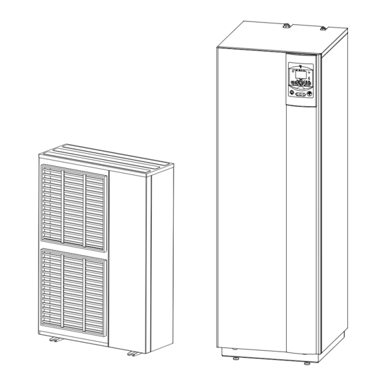
alféa excellia duo
Heat pump air/water
split 2 services
Outdoor unit
WOYG112LCT
WOYG140LCT
WOYK112LCT
WOYK140LCT
WOYK160LCT
Hydraulic unit
023159
Document n° 1481-13 ~ 04/02/2013
FR
NL
DE
EN
ES
PT
Installation and
operating manual
intended for professionals
To be saved for
future consultation
atlantic-comfort.com
IT
Advertisement

Subscribe to Our Youtube Channel
Related Manuals for Atlantic 023159


Summary of Contents for Atlantic 023159
- Page 1 Document n° 1481-13 ~ 04/02/2013 Heat pump air/water split 2 services Outdoor unit Hydraulic unit WOYG112LCT 023159 WOYG140LCT WOYK112LCT WOYK140LCT WOYK160LCT Installation and operating manual intended for professionals To be saved for future consultation atlantic-comfort.com...
- Page 2 capacity for handling refrigerants. Contents Description of the unit ......4 Package .
-
Page 3: Table Of Contents
Regulation system ....... 34 ....38 . - Page 4 Packing list Code Code Code 522664 700117 522665 700142 522666 700118 023159 522667 700143 522668 700163 Optional equipment Scope of application 1 Description of the unit Package 1 package 1 package...
- Page 5 Designation model alfea excellia duo Single phase Single phase 3-phase 3-phase 3-phase Nominal heating performances Heat output +7 °C / +35 °C - Floor heating system 10,80 13,50 10,80 13,00 15,17 -7 °C / +35 °C - Floor heating system 10,38 11,54 10,38...
- Page 6 Outside unit, Model excellia duo 11 & 14 single phase Overflow hole (Ø 20) Holes Ø 10) Sight of lower part 1290 3/8” 5/8” Front view Side view Top view Outside unit, Model excellia duo 11, 14 & 16 3-phase Sight of lower part 1290 Front view...
- Page 7 Hydraulic module 42,7 47,2 1817 1799 1256 1148 1093 Back view Side view Front view...
- Page 8 1 mbar = 10 mmCE = 100 Pa mbar 43907 ext. in 10000 2490 1000 ° C m /h 32500 1 mbar = 10 mmCE = 100 Pa 30000 mbar 27500 ext. in 25000 22500 20000 17500 15000 12500 10000 7500 5000 2500...
- Page 9 Description Model excellia duo 11 & 14 single phase Model excellia duo 11, 14 & 16 3-phase WO*K1**LCT Legend :...
- Page 10 Legend : Sensors : Operating principle Regulation functions Protection functions...
- Page 11 4 kW Heat produced 20 °C Energy from the air COP 4 1 kW Electrical energy consumed...
- Page 12 2 Installation 2.2.3 Containment of refrigerant circuits Regulation installation and maintenance conditions It’s necessary to ensure correct containment In case of subsequent failure and expertise, the Unpacking and reservations 2.2.1 Receipt 2.2.2 Handling 2.2.4 Accessories provided Installation position...
- Page 13 Installation of the outdoor unit 2.4.1 Installation precautions The outdoor unit must only be installed outdoor 1000 or more 1000 or more 1500 1000 Max. 500 Max. 500 or more or more or more 1500 1500 or more or more 1500 or more 1500...
- Page 14 2.4.2 Outdoor unit positioning 2.4.3 Condensate drain hose trace resistance to avoid it icing up. The trace resistance must heat not only the pipe but also the bottom of the appliance's condensate collection tank.
- Page 15 Installing the hydraulic unit 2.5.1 Installation precautions refrigerant connections. Refrigeration connections This appliance uses refrigerant R410A. 2.6.1 Rules and precautions Minimum necessary tools Manifold Provision on using tools that have been in regard to the guarantee if the above instructions are not observed.
- Page 16 Flared connections 2.6.2 Refrigeration connections is forbidden. only The minimum length of the refrigeration connections is 5 m for correct operation. POE refrigeration oil. Do not use mineral oil. 2.6.3 -0,4...
- Page 17 2.6.4 Shaping the refrigeration pipes 2.6.5 Take particular care positioning the tube opposite its connector so as not to risk damaging the The refrigeration circuit is very sensitive to dust and humidity: check that the area around the connection is clean and dry before removing the plugs protecting the refrigeration connectors.
- Page 18 This operation is reserved for installers familiar Method 3 empty Manifold refrigerant other than a HFC. ANNEX 1 building the refrigerant connections. Jeu de manomètres Unfavorables conditions : Manifold Manifold (manifold) Basse Haute pression pression Vacuomètre Liaison... liquide Pompe à vide Azote Haute pression...
- Page 19 First seal test Refrigeration connexion Plug (A) Schrader 3-way valve Manifold. Manifold Hex / Allen key of 4 mm Load orifice Azote Plug (B) Haute Service hose (blue) 10 bars max. pression fitted with valve push-button 30 mn mini Liaison... liquide Manifold Haute...
- Page 20 Additional charge 250 g page 17 in the liquid extraction position. LED2 LED1 R410A...
- Page 21 Hydraulic connecting 2.8.1 General Never use monoethylene glycol. In certain installations, the presence of different metals can cause corrosion problems; the formation of metal particles and sludge in the hydraulic circuit is then seen. In this case, it is advisable to use a corrosion inhibitor in the proportions indicated by its manufacturer.
- Page 22 2.8.2 2.8.5 Connecting the Fan convector circuit 2.8.3 Rinsing out the installation 2.8.4 Filling and purging the installation page 31 manometric height of the installation. Legend:...
- Page 23 Heating circulation pump speed settings 1 mbar = 10 mmCE = 100 Pa mbar Variable pressure ext. in radiators m /h ext. in 1 mbar = 10 mmCE = 100 Pa mbar ext. in Constant pressure m /h ext. in Cut off the electricity supply from the circulation pump for 30 seconds in order to release and authorise another start cycle.
- Page 24 2.10 Electrical connections 2.10.1 Characteristic of the electrical supply page 25 Connecting to regulation cards 2.10.2 General remarks on electrical connections Connecting to spring terminals...
- Page 25 2.10.3 2.10.4 Cable section and protection rating 32 A 20 A 32 A 20 A...
- Page 26 2.10.5 Electrical connections on the single phase outdoor unit side Cable clip Cover plate Power supply cable and Insulation (seal) Cover plate connection cable Cables CAUTION Secure cables so that they are not in Release contact with pipes and valves. Gas valve...
- Page 27 2.10.6 Electrical connections on the 3- phase outdoor unit side 2 3 L1 L2 L3 N INDOOR UNIT POWER Back...
- Page 28 Electrical connections on the hydraulic unit side hydraulic unit External faults the heat pump If the boiler connection option is used, the electric boost option must not be connected. Second heating circuit 230 V...
- Page 29 Hydraulic unit Outdoor unit single phase 1 2 3 230 V Hydraulic unit Outdoor unit 3-phase 1 2 3 L1 L2 L3 N 1 2 3 230 V L1 L2 L3 N...
- Page 30 B2 M B1 3 2 1 M B9...
- Page 31 2.11 Outdoor sensor 2.13 Commissioning 2.12 Room thermostat 2.12.1 Installing a room sensor page 35 B2 M In the case of 2 heating circuits, Room thermostat T55 Room thermostat radio T58 2.12.2 Installing a room control unit...
- Page 32 2.14 in zone 2, Then connect the other room thermostat and 2.15 In the case of 2 heating circuits page 38 English 42* 44* 48* page 38 Room appliance 1 Heating circuit 1 Commonly...
-
Page 34: Regulation System
3 Regulation system Auto Auto °C... - Page 35 Manual start button Auto page 58 page 55 Do not use during normal operation.
- Page 36 Description of the display Temperature control Xxxxxxxxxxxxxxxxxxxxxxxxxxx 3.3.1 Set to Xxxxxxxxxxxxxxxxxxxxxxxxxxx Xxxxxxxxxxxxxxxxxxxxxxxxxxx INFO PROG temperature ambiante temperature ambiante temperature ambiante...
- Page 37 2,75 ° C 2,25 1,75 1,25 0,75 0,25 ° C +4,5 -4,5 & & & & & & & & &...
- Page 38 Parametering the setting 3.4.2 Setting parameters 3.4.1 General ESC. 01.01...31.12 3.4.3 Date and time 00:00... 23:59 01.01... 31.12 1900... 2099 01.01... 31.12 25.03 01.01... 31.12 25.10 User interface English Temporary...
- Page 39 Heating time programme, circuit 1 Mon-Sun 6:00 22:00 --:-- --:-- --:-- --:-- Heating time programme, circuit 2 Mon-Sun 6:00 22:00 --:-- --:-- --:-- --:-- Mon-Sun 00:00 05:00 14:30 --:-- --:--...
- Page 40 Mon-Sun 8:00 20:00 --:-- --:-- --:-- --:-- Holidays, heating circuit 1 Period 1 01.01... 31.12 01.01... 31.12 Frost protection Holidays, heating circuit 2 Period 1 01.01... 31.12 01.01... 31.12 Frost protection Heating adjustment, circuit 1 20 °C... 35 °C 1 °C 8 °C...
- Page 41 180 min 30 min 1 °C 1 °C 0... 50 °C 1 °C 240 s 0... 95 °C 1 °C 0... 32 0... 32 Protection mode standards and instructions manufacturer performance of this function installation correctly This function can be stopped the adjustment on "Stop".
- Page 42 Cooling circuit 1 17... 40 °C Time program 5 6... 35 °C 6... 35 °C 8... 35 °C 8... 100 24 h 20... 50 °C 1 °C 20... 50 °C 1 °C 1... 10 °C 1 °C 6... 35 °C 6...
- Page 43 1041 8... 70 °C 1 °C Important Note : 1050 50 % 1060 0.5 °C 1010 1060 1080 1090 180 min 1091 30 min 1100 1 °C 1101 1 °C 1130 0... 50 °C 1 °C 1134 240 s 1150 1151 0...
- Page 44 1610 65 °C 1612 8 °C... 1620 Programme Heating circuit time programme: Off-peak tariff* : 1640 1641 1642 Saturday 2056 8... 35 °C 2803 240s 2843 1 °C 8 min 2844 8... 100 °C 1 °C 2862 5 min 2873 240 s 2882 2884...
- Page 45 3692 Substitute 3700 1 °C 3701 1 °C 3705 20 min 3720 3723 30 min 5024 0... 20 °C 1 °C 5030 90 min 5055 10... 95 °C 1 °C 5057 Summer 5061 Release of 5093 5710 5711 5715 5731 Diverting valve 5806...
- Page 46 6420 1... 56 6421 LPB system 6600 Error 6711 6800 6802 6804 6806 6808 6810 6812 6814 6816 6818 7070 7071 0... 240 7073 0... 12 7141 7142 7150 7700...
- Page 47 7710 7712 7716 7719 7722 7723 7724 7725 7820 7821 7822 7823 7824 7825 7830 7832 7849 Open 7911 7912 7913 7973 7974 7975 7976 7977 7978 7996 Open State 8000 8001 8003 8004 8006 8007 8010 8011 8022 Generator diagnosis 8402 8403 8406...
- Page 48 8410 0... 140 °C 8412 0... 140 °C 8413 8414 8425 8450 8454 8455 0... 65535 8456 8457 0... 65535 8499 8505 8510 8511 8512 8513 8515 Diagnostics consumers 8700 8701 8702 8703 8704 8730 8731 8732 8740 0... 50 °C 8743 0...
- Page 49 8770 0... 50 °C 8773 0... 140 °C 8820 8821 8830 0... 140 °C 8840 8841 0... 199999 8842 8843 0... 65535 8900 0... 140 °C 8950 0... 140 °C 8957 0... 140 °C 8980 8981 9031 9032 9033 9034 9035 9050 9051...
-
Page 50: Overall Hydraulic Layout
4 Overall hydraulic layout... - Page 52 Option(connector) Pressure Refer to the sensor technical manual Thermistor (compressor) Thermistor (outdoor) Thermistor (pipe) Thermistor (discharge) Expansion Fuse valve coil Thermistor (heat sink) Thermistor (pipemid) Expansion valve coil (Injecrtion) Thermistor (expansion) Solenoid coil (injection) Compressor Solenoid coil Fuse Terminal Fan motor 1 (upper) Choke coil Fan motor 2...
- Page 53 Expansion valve coil (Inj) Solenoid coil (Inj) Thermistor Inj expansion valve Thermistor heat exchanger mid Thermistor heatsink PFC Thermistor discharge pipe Thermistor heat exchanger out Compressor Thermistor Thermistor Thermistor compressor Pressure sensor Reactor fan Solenoid P.F.C. coil Expansion valve coil Fan motor 1 (upper) Fan motor 2...
-
Page 55: Troubleshooting
6 Troubleshooting Faults displayed on the hydraulic unit Hydraulic unit page 58 Hydraulic unit... - Page 56 Faults displayed on the single phase outdoor unit ERROR ENTER ERROR...
- Page 57 Faults displayed on the 3-phase outdoor unit ERROR ENTER ERROR...
- Page 58 Information display page 55 8006 8022 8003 8011 8000 8001 8004 8700 8740 8743 8770 8773 8830 8410 8412 8900...
-
Page 60: Maintenance Of The Installation
Maintenance of the installation Hydraulic checks it is essential that you look for any leaks. Descaling Checking the outdoor unit Checking the refrigeration circuit : Electrical checks... -
Page 61: Maintenance
8 Maintenance Emptying the hydraulic unit Distribution valve ACI check Check ACI voltage Connecting U = + 0 + 6,5 V ACI connecting: on the tank mass. on the electrode connector. 9 Instructions for the user... -
Page 62: Quick-Start Procedure
10 Quick-start procedure 10.1 Start-up check-list 10.1.1 Before starting-up Sight checks page 12 Hydraulic checks page 15 Refrigeration connections and checks page 16 page 19 Electrical checks page 22 page 25... - Page 63 10.1.2 Starting-up page 28 Outdoor unit checks Hydraulic unit checks Room control...
- Page 64 10.2 Settings sheet Boiler backup Preliminary settings 3700 language operator section 3705 swith-off delay hour / minutes time & date Miscellaneous day / month time & date 6420 input H33 function year time & date 6100 OT sensor correction 5700 6120 frost protection on/off Heating circuit No.
- Page 65 10.3 Start-up data sheet Site Installer Outdoor unit Hydraulic unit Checks Operating voltage & current on outdoor unit Reading in HEATING operating mode °C °C °C °C °C °C °C °C °C °C °C °C °C °C °C Hydraulic system of hydraulic unit Options &...
- Page 68 Date of installation : www. atlantic-comfort.com www.atlantic.fr Société Industrielle de Chauffage SATC - BP 64 - 59660 MERVILLE - FRANCE Contact of your heating technician or your after-sales service.
Need help?
Do you have a question about the 023159 and is the answer not in the manual?
Questions and answers