Table of Contents
Advertisement
Advertisement
Table of Contents

Subscribe to Our Youtube Channel
Related Manuals for Atlantic AOYA 18 LALL


Summary of Contents for Atlantic AOYA 18 LALL
- Page 1 Evolution Document n° 1397-11 ~ 22/02/2013 Heat pump air/water split single service Outdoor unit Hydraulic unit AOYA 18 LALL 023140 AOYA 24 LALL 023146 AOYA 30 LBTL Installation and operating manual intended for professionals To be saved for future consultation...
-
Page 2: Description Of The Unit
capacity for handling refrigerants. Contents Description of the unit ......4 Package . -
Page 3: Table Of Contents
Regulation system ....... 30 ....30 . - Page 4 Packing list Heat pump Outdoor unit Hydraulic unit Model Code Model Code Model Code 522644 AOYA 18 LALL 700718 023146 522645 AOYA 18 LALL 700718 522646 AOYA 24 LALL 700724 023140 522647 AOYA 30 LBTL 700730 Optional equipment Scope of application...
- Page 5 Designation model ..alféa Evolution ..5 ..6 ..8 ..10 Nominal heating performances (outdoor temperature/ initial temperature) Heat output +7 °C / +35 °C - Floor heating system .
-
Page 6: Outdoor Unit
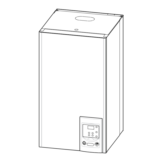
Outdoor unit, Model Evolution5, Evolution 6, Evolution 8 Orifice d’écoulement (Ø 20) 4 trous Ø 10) Vue de dessous 1/4” 1/4” 1/2” 5/8” Vue de face Vue de côté Vue de dessus Outdoor unit, Model Evolution 10 Orifice d’écoulement (Ø 20) 4 trous Ø... - Page 7 Hydraulic unit 832,5 Side view Front view Dimensions in mm...
- Page 8 1 mbar = 10 mmCE = 100 Pa 43907 10000 2490 1000 ° C m /h 1 mbar = 10 mmCE = 100 Pa 32500 30000 27500 25000 22500 20000 17500 15000 12500 10000 7500 5000 2500 °C m /h Ohmic values of the sensors (Hydraulic unit) 10000...
- Page 9 Description Model Evolution 10 Model Evolution 5, Evolution 6, Evolution 8 Legend: Outdoor unit components...
-
Page 10: Operating Principle
Legend: Heating return Drain valve 10. Safety valve 11. Manometer 12. Manual drainer 14. Condenser Side view Front view Hydraulic unit components Operating principle Regulation functions Protection functions... - Page 11 4 kW 20 °C Heat produced Energy from the air COP 4 1 kW Electrical energy consumed Heat pump operating principle...
- Page 12 2 Installation Regulation installation 2.2.3 Containment of refrigerant circuits and maintenance conditions It’s necessary to ensure correct containment In case of subsequent failure and expertise, the Unpacking and reservations 2.2.1 Receipt 2.2.2 Handling 2.2.4 Accessories provided Installation position (Depending on the model)
-
Page 13: Installation Of The Outdoor Unit
Installation of the outdoor unit 2.4.1 Installation precautions The outdoor unit must only be installed outdoor page 14 100 mm 100 mm 600 mm 250 mm 100 à 300 mm 300 mm pour accès 250 mm 250 mm 300 mm pour accès pour accès minimum... - Page 14 Minimum Maximum Maxi level HP model Liquid length (L) length * (L) difference (D) mini mini R410A. Pipe diameters (in inches) and permissible lengths (in metres) H > 50 mm 2.4.2 Outdoor unit positioning Dans les régions fréquemment enneigées, (H) doit être supérieur à la couche moyenne de neige. 2.4.3 Condensate drain hose Depending on the model Suivant modèle...
- Page 15 Installing the hydraulic unit 2.5.1 Installation precautions 2.5.2 Positioning the hydraulic unit 350 mm mini 350 mm mini 538 mm mini 300 mm mini 1000 mm 300 mm 118 mm mini 188 mm 418 mm mini refrigerant connections. Mounting bracket...
- Page 16 Refrigeration connections This appliance uses refrigerant R410A. 2.6.1 Rules and precautions 2.6.2 Refrigeration connections Minimum necessary tools Manifold only The minimum length of the refrigeration connections is 5 m for correct operation. Provision on using tools that have been in 2.6.3 Accessing the hydraulic module’s regard to the guarantee if the above instructions refrigerant connections...
- Page 17 2.6.4 2.6.5 Shaping the refrigeration pipes 2.6.6 2.7, page 19 Take particular care positioning the tube opposite its connector so as not to risk damaging the threads. A carefully aligned connector can being required. The refrigeration circuit is very sensitive to dust and humidity: check that the area around the connection is clean and dry before removing the plugs protecting the refrigeration connectors.
- Page 18 Diameter of Male-female Outdoor unit Hydraulic unit HP model refrigeration adapter connections connections connections (reduction) Hydraulic unit Outdoor unit...
- Page 19 This operation is reserved for installers familiar Method 3 empty Manifold refrigerant other than a HFC. ANNEX 1 building the refrigerant connections. Jeu de manomètres Unfavorables conditions : Manifold (manifold) Basse Haute pression pression Vacuomètre Liaison... liquide Pompe à vide Azote Haute pression...
- Page 20 First seal test Liaison frigorifique Schrader Bouchon (A) Manifold. Vanne 3 voies Manifold Clé hexagonale de 4 mm Orifice de charge Azote Haute 10 bars max. Bouchon (B) pression Flexible de service (bleu) 30 mn mini muni d’un poussoir de valve Connexion of the hose on the "Gaz"...
- Page 21 Connecting the heating 2.8.2 Rinsing out the installation circuit hydraulically 2.8.1 General 2.8.3 Filling and purging the installation page 30 Never use monoethylene glycol. manometric height of the installation. 2.8.4 Connecting a fan-convectors circuit hydraulic unit bleeder valve...
- Page 22 Speed settings of the HP pump 1 mbar = 10 mmCE = 100 Pa Variable pressure radiators m /h 1 mbar = 10 mmCE = 100 Pa Constante pressure heating system. m /h Operation signals the HP circulator...
- Page 23 Pression variable Variable pressure Cut off the electricity supply from the circulation Venting pump for 30 seconds in order to release and Dégazage authorise another start cycle. Pression constate Constante pressure Pump dial...
- Page 24 2.10 Electrical connections 2.10.1 Characteristic of the electrical supply page 25 2.10.2 General remarks on electrical connections Connecting to regulation cards Connecting to spring terminals...
- Page 25 2.10.3 2.10.4 Cable section and protection rating Heat pump Cable connection Curve D circuit Model (Phase, Neutral, Earth) breaker size 16 A 16 A 20 A Heat pump electrical back-ups Electrical back-ups supply Cable Curve C circuit Model Nominal current (Phase, Neutral, Earth) breaker size 32 A...
- Page 26 2.10.5 Electrical connections on the outdoor unit side Model Evolution 5, Evolution 6 & Evolution 8 Model Evolution 10 Déposer la façade (2 vis) Déposer la façade (2 vis) Déposer le capot (1 vis) Access to outdoor unit’s terminal block Bornier Déposer le capot (1 vis)
- Page 27 Cable clip Power supply Cover plate cable and Cover plate Insulation (seal) connection cable Cables CAUTION Secure cables so that they are not in Release contact with pipes and valves. Gas valve Finalisation of connection to outdoor unit 2.10.6 Electrical connections on the hydraulic unit side Access to hydraulic unit electric box and description...
- Page 28 Hydraulic unit Outdoor unit 1 2 3 230 V hydraulic unit If the boiler connection option is used, the electric boost option must not be connected. External faults the heat pump...
-
Page 29: Room Thermostat
B2 M B1 3 2 1 M B9 Connections to the heat pump regulator (accessories and options) 2.12 Room thermostat 2.11 Outdoor sensor M, B2, B1 1, 2, 3... - Page 30 2.13 Start-up 2.14 2.15 +/OK. +/OK. page 36 English...
-
Page 32: Regulation System
3 Regulation system User interface User interface Ref. Function -/ESC -/ESC page 39 Do not use during normal operation... - Page 33 Auto Auto °C Room control unit and room thermostat (option) Ref. Function Marche Manual start button Arrêt Auto page 39 page 48...
- Page 34 Temperature control 3.3.1 Manual adjustment...
- Page 35 +4,5 -4,5 & & & & & & & & & Corrective actions in the case of discomfort...
- Page 36 Parametering the setting 3.4.1 General 3.4.2 Setting parameters 1...7 1...12 3.4.3 Line Function Setting range Setting Basic or display increment setting Time and date 1:00 01.01... 31.12 1.01 2004... 2099 2004 0...99.9 Heating time program 6:00 22:00 --:-- --:-- --:-- --:--...
- Page 37 Line Function Setting range Setting Basic or display increment setting Heating adjustment Remark 50 % 0:00 5:00 14:30 17:00 --:-- --:--...
- Page 38 Line Function Setting range Setting Basic or display increment setting Heat pump Released Additional generator 20 min Inputs / outputs test...
- Page 39 Information display Line Designation page 48 3.5.1 Status list Designation Designation...
- Page 40 Optional boiler connection kit page Optional electrical back-ups kit...
- Page 41 Parameter 90. page 42 page 43 4.1.1 Hydraulic connections if boiler connection if boiler connection 4.1.2 Electrical connections 4.1.3 Parametering the setting 82-83-84 if electric back-ups 4.1.4 Special cases...
- Page 42 See detailed 1 heating circuit instructions on page 41. Overall hydraulic layout Legend...
- Page 43 See detailed instructions on page 41. Overall hydraulic layout Legend - DHW kit SSa - DHW sensor VD - Distribution valve...
- Page 44 R (R) S (S) C (T) CN71 CN801 CN73 CN72 CN40 CN70 CN30 AOYA 18LALL Color Codes...
- Page 45 CN90 CN64 CN42 CN40 CN200 CN400 1 2 3 4 5 1 2 3 4 5 6 7 8 9 1 2 3 4 1 2 3 4 5 1 2 3 4 5 6 7 8 9 1 2 3 4 CN62 CN65 1 2 3 4 5...
- Page 46 X82 X83...
-
Page 48: Troubleshooting
6 Troubleshooting Faults displayed on the hydraulic unit Hydraulic unit Heat pump operation Error number Error contents Error location despite the error page Hydraulic unit Diodes display Error contents... - Page 49 Faults displayed on the outdoor unit Diode display Erroneous element Diode display Erroneous element...
-
Page 50: Maintenance Of The Installation
7 Maintenance of the installation Hydraulic checks Checking the outdoor unit essential that you look for any leaks. Checking the refrigeration circuit Electrical checks 8 Maintenance Distribution valve Emptying the hydraulic unit 9 Instructions for the user... -
Page 52: Quick-Start Procedure
10 Quick-start procedure 10.1 Start-up check-list 10.1.1 Before starting-up Sight checks page 12 Hydraulic checks page 15 Refrigeration connections and checks page 16 page 19 Electrical checks page 22 page 25... - Page 53 10.1.2 Starting-up page 28 2 hours before starting up the tests Outdoor unit checks Hydraulic unit checks Room control page 28...
- Page 54 10.2 Settings sheet Parameter Designation Set to Preliminary settings Heating circuit Boiler connection Various Faults Heat pump page 48...
- Page 55 10.3 Start-up data sheet Site Installer Outdoor unit Hydraulic unit Checks Operating voltage & current on outdoor unit Reading in HEATING operating mode Hydraulic system of hydraulic unit Options & Accessories : Control settings...
- Page 56 Date of installation : www.atlantic.fr Société Industrielle de Chauffage SATC - BP 64 - 59660 MERVILLE - FRANCE Contact of your heating technician or your after-sales service.
Need help?
Do you have a question about the AOYA 18 LALL and is the answer not in the manual?
Questions and answers