Table of Contents
Advertisement
Quick Links
Advertisement
Table of Contents

Related Manuals for Jung Smart Control SC 1000 KNX


Summary of Contents for Jung Smart Control SC 1000 KNX
- Page 1 Product documentation Smart Control Art. No. SC 1000 KNX ALBRECHT JUNG GMBH & CO. KG Volmestraße 1 58579 Schalksmühle Telefon: +49.23 55.8 06-0 Telefax: +49.23 55.8 06-2 04 kundencenter@jung.de www.jung.de Service Center Kupferstr. 17-19 44532 Lünen Germany Issue: 05.12.2013 14505800 1v5.2...
-
Page 2: Table Of Contents
Product documentation Contents 1 Product definition ........................ 1.1 Product catalogue ......................1.2 Function .......................... 1.3 Accessories ........................2 Installation, electrical connection and operation ............. 2.1 Safety instructions ......................2.2 Device components ......................2.3 Fitting and electrical connection ................... 2.4 Commissioning ...................... - Page 3 Product documentation 4.2.4.2.9 "Controller operating mode" function ............ 4.2.4.2.10 "Setpoint shift" function ................ 4.2.4.2.11 Status LED ................... 4.2.4.2.12 Disabling function ................. 4.2.4.2.13 Alarm signal ..................4.2.4.3 Room temperature controller ............... 4.2.4.3.1 Operating modes and operating mode change-over ......4.2.4.3.2 Control algorithms and calculation of command values .......
-
Page 4: Product Definition
Product definition 1 Product definition 1.1 Product catalogue Product name: Smart Control Use: Sensor / Display Design: FM (flush-mounted) Art. No. SC 1000 KNX 1.2 Function The Smart Control is a control and display unit for controlling and visualising building functions. The device has a TFT graphic colour screen (10.9 cm, 800 x 480 pixels, 16.7 million colours) with a touchscreen sensor surface. - Page 5 Product definition The operation concept of an operating element on the push-button extension module can be configured optionally in the ETS either as a rocker function or alternatively as a push-button function. With the rocker function and the double-surface push-button function, the button arrangement can be set either as "vertical"...
- Page 6 Product definition configured using the ETS and via a special timer display page, has up to 8 switching times. The switching times affect KNX channels (1...30) configured in the device and can handle the data formats switching (1 bit), Value 1 byte (incl. brightness value and position setting) and Value 2 byte and similarly transmit telegrams to the bus.
-
Page 7: Accessories
Product definition 1.3 Accessories KNX module Art. No. MSC 1000 KNX Push-button extension module, 1-gang Art. No. 4091 TSEM Push-button extension module, 2-gang Art. No. 4092 TSEM Push-button extension module, 3-gang Art. No. 4093 TSEM Push-button extension module, 4gang Art. -
Page 8: Installation, Electrical Connection And Operation
Installation, electrical connection and operation 2 Installation, electrical connection and operation 2.1 Safety instructions Electrical equipment may only be installed and fitted by electrically skilled persons. The applicable accident prevention regulations must be observed. Failure to observe the instructions may cause damage to the device and result in fire and other hazards. -
Page 9: Device Components
Installation, electrical connection and operation 2.2 Device components Figure 1: Device components front side (1) The device has a TFT graphic colour screen (10.9 cm, 800 x 480 pixels) with a touchscreen sensor surface (2) Button V "Return" to the start page (3) Button "Scroll"... - Page 10 Installation, electrical connection and operation Figure 2: Device components at the back (with attached KNX communication module) (8) KNX communication module (9) Connection terminals for power supply DC 24 V (- / +) nb: Reserved for future use (10) Connection for KNX bus cable (11) Connector socket for push-button extension module (12) Guide to the connection for future extension (13) Connector socket (reserved for future use)
-
Page 11: Fitting And Electrical Connection
Installation, electrical connection and operation 2.3 Fitting and electrical connection DANGER! Electrical shock on contact with live parts in the installation environment. Electrical shocks can be fatal. Before working on the device, disconnect the power supply and cover up live parts in the working environment. - Page 12 Installation, electrical connection and operation Position the decorative frame (17) on the supporting ring. Connect the external power supply... The Smart Control needs an external DC power supply for supplying the device electronics (figure 4). It is not possible to use the unchoked output of KNX power supplies as device power supply! The power supply must be provided by an additional device (e.g.
- Page 13 Installation, electrical connection and operation Assembling and connecting device with push-button extension module Figure 5: Device fitting with push-button extension module with 3-gang supporting frame (16) Box screws (24) Supporting frame 3-gang (25) Connecting cable for push-button sensor extension module with plug (26) Push-button extension module (27) Fastening screws (28) Design control surfaces for the extension module...
- Page 14 Installation, electrical connection and operation Position the decorative frame (17) on the supporting ring. Assembling and connecting push-button extension module... Guide the connection cable of the push-button extension module (25) between the supporting frame and frame. Fix push-button extension module (26) to supporting frame using the plastic screws (27) enclosed.
-
Page 15: Commissioning
Installation, electrical connection and operation 2.4 Commissioning After the device has been connected to the power supply and to the bus and mounted on the wall, it can be put into operation. The commissioning is essentially confined to the programming of the actuator via the ETS. - Page 16 Installation, electrical connection and operation Figure 6: Programming screen The programming status is terminated automatically after successfully programming the physical address by the ETS. The device returns to the administrator page or branches to the main menu level once the return time to the start page has elapsed since activating the programming mode.
- Page 17 Installation, electrical connection and operation i The device coupling unit is already functional immediately after completion of the ETS programming operation. Therefore, it is possible that telegrams might be transmitted to the bus even during the initialization state (e.g. from the integrated room temperature controller).
-
Page 18: Operation
Installation, electrical connection and operation 2.5 Operation The Smart Control is a control and display unit for controlling and visualising building functions. The device has a TFT graphic colour screen (10.9 cm, 800 x 480 pixels, 16.7 million colours) with a touchscreen sensor surface. -
Page 19: Technical Data
Technical data 3 Technical data Ambient conditions Storage/transport temperature -25 ... +60 °C Ambient temperature 0 ... +35 °C Protection class Relative humidity 10 ... 90 % rel. humidity (No moisture condensation) Storage/transport humidity 5 ... 90 % rel. humidity Dimensions Dimensions W×H 71×142 mm... -
Page 20: Software Description
Software specification 4 Software description 4.1 Software specification ETS search paths: - Push button / Push button, general / Smart Control BAU used: TP-UART + µC KNX type class: 3b device with cert. Physical layer + stack Configuration: S-mode standard AST type: "00"... -
Page 21: Software "Smart Control 501511
Software "Smart Control 501511" Scope of functions 4.2 Software "Smart Control 501511" 4.2.1 Scope of functions Functions of the display and touch sensor surface The Smart Control is a control and display unit for controlling and visualising building functions. The device has a TFT graphic colour screen (10.9 cm, 800 x 480 pixels, 16.7 million colours) with a touchscreen sensor surface. - Page 22 Software "Smart Control 501511" Scope of functions Functions of the integrated room temperature controller Various operating modes can be activated: Comfort, Standby, Night and Frost/heat protection Each operating mode can be assigned its own temperature-setpoints (for heating and/or cooling). Comfort extension possible using presence button in Night or Frost/heat protection mode. Configurable duration of the comfort extension.
- Page 23 Software "Smart Control 501511" Scope of functions Integrated scene control. Internal storage of up to eight scenes with eight output channels, recall of internal scenes by means of a presettable scene number, selection of object types for the output channels; for each scene, the storage of the individual output values and the transmission of the output values can be permitted or inhibited;...
-
Page 24: Notes On Software
Software "Smart Control 501511" Notes on software 4.2.2 Notes on software ETS configuration and commissioning For configuration and commissioning of the device, ETS3.0 Version f or ETS4.0.6 or higher is required. Advantages with regard to downloading (significantly shorter loading times) and parameter programming using the integrated database plug-in can be expected only if this ETS versions are used. -
Page 25: Object Table
Software "Smart Control 501511" Object table 4.2.3 Object table Number of communication objects: (max. object number 254 - gaps in between) Number of addresses (max): Number of assignments (max): 4.2.3.1 Push-button extension module Objects for rocker or button functions Function: Switching Object Function... - Page 26 Software "Smart Control 501511" Object table Function: Venetian blind Object Function Name Type Flag Short time operation B.Module rocker/ 1-bit 1.007 C, -, T, (R) B.Module button 1 Description 1-bit object for the transmission of telegrams with which a Venetian blind or shutter drive motor can be stopped or with which the blind slats can be adjusted by short time operation.
- Page 27 Software "Smart Control 501511" Object table Function: 2-byte value transmitter Object Function Name Type Flag Temperature value B.Module rocker/ 2 byte 9.001 C, W, T, B.Module button 1 Description 2 -byte object for the transmission of a temperature value from 0 °C to 40 °C. If the adjustment of the value is enabled, the object can transmit telegrams cyclically after a long press with which the value can be reduced or increased by 1 K.
- Page 28 Software "Smart Control 501511" Object table Function: 2-channel operation Object Function Name Type Flag Channel 1 value B.Module rocker/ 1 byte 5.xxx C, -, T, (R) B.Module button 1 Description 1-byte object for the transmission of value telegrams, if 2-channel operation is activated.
- Page 29 Software "Smart Control 501511" Object table Function: 2-channel operation Object Function Name Type Flag Channel 2 value B.Module rocker/ 2 byte 9.001 C, -, T, (R) B.Module button 1 Description 2-byte object for the transmission of value telegrams, if 2-channel operation is activated.
- Page 30 Software "Smart Control 501511" Object table Objects for status LED Function: Status LED in case of rocker function Object Function Name Type Flag Status LED top B.Module 1-bit 1.xxx C, W, -, (R) rocker 1 Description 1-bit object for activation of the status LED. Function: Status LED in case of rocker function Object...
- Page 31 Software "Smart Control 501511" Object table Function: Status LED in case of push button function Object Function Name Type Flag Status LED B.Module button 1 byte 5.xxx, C, W, -, (R) 6.xxx, 20.102 Description 1-byte object for activation of the status LED. Objects for alarm message Function: Alarm signal...
-
Page 32: Light Scene Function
Software "Smart Control 501511" Object table 4.2.3.2 Light scene function Object for light scene function Function: Light scene function Object Function Name Type Flag 66...73 Switching B.Scene- 1-bit 1.001 C, W, T, output 1 Description 1-bit objects for controlling up to eight actuator groups (ON, OFF). Function: Light scene function Object... -
Page 33: Room Temperature Controller
Software "Smart Control 501511" Object table 4.2.3.3 Room temperature controller Objects for room temperature measurement Function: Room temperature measurement Object Function Name Type Flag Actual-temperature C.Output 2 byte 9.001 C, -, T, R Description 2-byte object for the display of the actual temperature (room temperature), which is determined by the controller. - Page 34 Software "Smart Control 501511" Object table Objects for operating mode change-over Function: Operating mode switchover Object Function Name Type Flag Operating mode switchover C.Input 1 byte 20.102 C, W, T, Description 1-byte object for change-over of the operating mode of the controller according to the KNX specification.
- Page 35 Software "Smart Control 501511" Object table Function: Operating mode switchover Object Function Name Type Flag Operating mode forced- C.Input 1 byte 20.102 C, W, T, control Description 1-byte object for forced change-over (highest priority) of the operating mode of the controller according to the KNX specification. This object is only available in this way when the operating mode change-over is to take place over 1 byte (parameter-dependent).
- Page 36 Software "Smart Control 501511" Object table Objects for controller status Function: Controller status Object Function Name Type Flag Controller status C.Output 1-bit 1.001 C, -, T, (R) Description 1-bit object for single status feedback of configured controller functions. This object is only available in this way when a part of the controller status is to be transmitted singly as 1-bit information (parameter-dependent).
- Page 37 Software "Smart Control 501511" Object table Function: Controller status Object Function Name Type Flag KNX status operating mode C.Output 1 byte 20.102 C, -, T, (R) Description 1-byte object used by the controller to output the operating mode in the event of forced position.
- Page 38 Software "Smart Control 501511" Object table Function: Disable controller Object Function Name Type Flag Disable additional level C.Input 1-bit 1.001 C, W, -, (R) Description 1-bit object for deactivating the additional level of the controller. Polarity: Additional level deactivated = "1", additional level activated = "0". This object is only available in this way if two-level heating or cooling operation is configured.
- Page 39 Software "Smart Control 501511" Object table Function: Command value Object Function Name Type Flag Command value for heating/ C.Output 1 byte 5.001 C, -, T, (R) cooling / command value, basic level Description 1-byte object to output the combined continuous command value of the heating and cooling mode.
- Page 40 Software "Smart Control 501511" Object table Function: Command value Object Function Name Type Flag Cmd. value, add. heating C.Output 1-bit 1.001 C, -, T, (R) (PWM) Description 1-bit object to output the continuous PWM command value for additional heating in two-level operation. This object is only available in this way if the type of feedback control is configured to "Switching PI control (PWM)".
- Page 41 Software "Smart Control 501511" Object table Object for command value output, cooling Function: Command value Object Function Name Type Flag Command value for cooling / C.Output 1 byte 5.001 C, -, T, (R) command value, basic cooling Description 1-byte object to output the continuous command value of the cooling mode. In two-level cooling mode, command value output for the basic cooling.
- Page 42 Software "Smart Control 501511" Object table Function: Command value Object Function Name Type Flag Cmd. value, add. cooling C.Output 1-bit 1.001 C, -, T, (R) (PWM) Description 1-bit object to output the continuous PWM command value for additional cooling in two-level operation. This object is only available in this way if the type of feedback control is configured to "Switching PI control (PWM)".
- Page 43 Software "Smart Control 501511" Object table Object for additional command value output, PWM additional heating and combined valve PWM additional heating/cooling Function: Command value Object Function Name Type Flag PWM cmd. value, add. C.Output 1 byte 5.001 C, -, T, (R) heating Description 1-byte object to output the internal continuous command value of a PWM...
- Page 44 Software "Smart Control 501511" Object table Object for additional command value output, PWM additional cooling Function: Command value Object Function Name Type Flag PWM cmd. value, add. C.Output 1 byte 5.001 C, -, T, (R) cooling Description 1-byte object to output the internal continuous command value of a PWM feedback controller for additional cooling in two-level operation.
- Page 45 Software "Smart Control 501511" Object table Function: Basic setpoint shifting Object Function Name Type Flag Preset setpoint shifting C.Input 1 byte 6.010 C, W, -, (R) Description 1-byte object for setting a basic setpoint shifting, e.g. of a controller extension. The value of a counter value in the communication object is 0.5 K.
- Page 46 Software "Smart Control 501511" Object table Function: Fan controller Object Function Name Type Flag Ventilation, fan level 1 C.Output 1-bit 1.001 C, -, T, R Description 1-bit object for switching activation of the first fan level. This object is only available in this way when the fan control is to take place over 8 x 1 bit and at least one fan level is enabled (parameter-dependent).
- Page 47 Software "Smart Control 501511" Object table Function: Fan controller Object Function Name Type Flag Ventilation, fan level 7 C.Output 1-bit 1.001 C, -, T, R Description 1-bit object for switching activation of the seventh fan level. This object is only available when the fan control is to take place over 8 x 1 bit and at least seven fan levels are enabled (parameter-dependent).
- Page 48 Software "Smart Control 501511" Object table Function: Fan controller Object Function Name Type Flag Ventilation visualisation C.Output 5.010 C, -, T, R byte Description 1-byte object for additional value-guided acknowledgement of the active fan level. Value meaning: "0" = Fan OFF, "1" = level 1 active, "2" = level 2 active, ..., "8"...
-
Page 49: Display
Software "Smart Control 501511" Object table 4.2.3.4 Display Objects for date and time Function: Setting time Object Function Name Type Flag Time D.Input 3 byte 10.001 C, W, -, (R) Description 3-byte object for setting the time of the internal system clock. The system clock controls the display of the time in the device display and timer. - Page 50 Software "Smart Control 501511" Object table Object for activating the display background light Function: Switching backlighting Object Function Name Type Flag Backlighting D.Input 1-bit 1.001 C, W, -, (R) On/Off Description 1-bit object to switch the backillumination of the LC display (polarity configurable).
- Page 51 Software "Smart Control 501511" Object table Function: Channel function "switching" Object Function Name Type Flag Switching feedback D.Output 1-bit 1.xxx C, W, T, Channel 1 Description 1-bit object for giving feedback on a switching state to the device. This influences the status text and status icon that can be displayed in the display area of the channel element.
- Page 52 Software "Smart Control 501511" Object table Function: Channel function "Dimming (Brightness value)" Object Function Name Type Flag Dimming (Brightness value) D.Output 1 byte 5.001 C, W, T, Channel 1 Description 1-bit object for transmitting brightness value telegrams (0...255) if the sensor element is touched.
- Page 53 Software "Smart Control 501511" Object table Function: Channel function "Venetian blind (Step/Move/Step) Object Function Name Type Flag Dimming Feedb. Blind/shutter D.Output 1 byte 5.001 C, W, -, (R) height Channel 1 Description 1-byte object for receiving position feedback telegrams for the blind/shutter height, which a blind or rolling shutter actuator transmits, for example.
- Page 54 Software "Smart Control 501511" Object table Function: Channel function "Blind (position)" Object Function Name Type Flag Dimming Feedb. Blind/shutter D.Output 1 byte 5.001 C, W, -, (R) height Channel 1 Description 1-byte object for receiving position feedback telegrams for the blind/shutter height, which a blind or rolling shutter actuator transmits, for example.
- Page 55 Software "Smart Control 501511" Object table Function: Channel function "1-byte value transmitter" Object Function Name Type Flag 1-byte value transm. D.Output 1 byte 5.001, C, W, T, feedback Channel 1 5.010 Description 1-byte object for receiving brightness value feedbacks that an activated actuator transmits, for example.
- Page 56 Software "Smart Control 501511" Object table Function: Channel function "ASCII Text" Object Function Name Type Flag ASCII text 2 D.Input 16.000 C, W, T, Channel 1 byte Description 14-byte object, which can receive ASCII character chains of maximum 14 characters to show a running text on the display (Part 2 of the running text). Objects for weather stations display page (alternative to KNX channels 24...30) Function: Weather station display...
- Page 57 Software "Smart Control 501511" Object table Function: Weather station display Object Function Name Type Flag Visual. Brightness sensor 2 W.Brightness 2 byte 9.004 C, W, -, (R) sensor 2 Description 2-byte object to receive a value telegram for any brightness value (e.g. "Sun South"...
- Page 58 Software "Smart Control 501511" Object table Function: Weather station display Object Function Name Type Flag Azimuth visualisation W.Azimuth 1 byte 5.003 C, W, -, (R) Description 1-byte object to receive a value telegram for the current sun status (azimuth angle). The measured value must be made available to the device via the bus in the format "°"...
- Page 59 Software "Smart Control 501511" Object table Function: Weather station display Object Function Name Type Flag Visualization W.External value 3 2 byte 9.xxx C, W, -, (R) external value 3 Description 2-byte object to receive and display any value telegram in compliance with KNX DPT 9.xxx.
- Page 60 Software "Smart Control 501511" Object table Function: Limiting value monitoring for weather station display Object Function Name Type Flag Limiting value W.Lim. value 1-bit 1.xxx C, W, -, (R) Brightness sensor 3 brightness sensor Description 1-bit object to receive a limiting value telegram for the third brightness value. "0"...
- Page 61 Software "Smart Control 501511" Object table Function: Limiting value monitoring for weather station display Object Function Name Type Flag Limiting value ext. value 2 W.Limiting value 1-bit 1.xxx C, W, -, (R) external value 2 Description 1-bit object to receive a limiting value telegram for the second external measured value.
-
Page 62: Functional Description
Software "Smart Control 501511" Functional description 4.2.4 Functional description 4.2.4.1 Display functions The Smart Control is a control and display unit for controlling and visualising building functions. The device has a TFT graphic colour screen (10.9 cm, 800 x 480 pixels, 16.7 million colours) with a touchscreen sensor surface. - Page 63 Software "Smart Control 501511" Functional description i As long as the device has not yet been programmed with application data in the ETS, a demo project is present in the device. The demo project can be recalled by pressing the "Demo"...
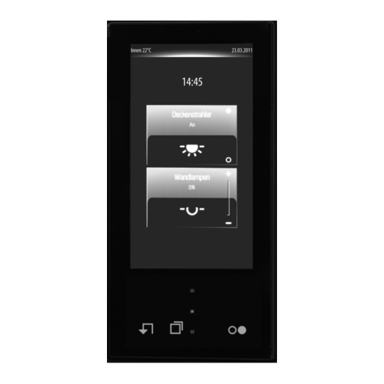
- Page 64 Software "Smart Control 501511" Functional description The current time is displayed on the start page in the upper display area provided that the time display is enabled in the ETS. The start page can be completely hidden optionally in the ETS. If the start page is available, a time-controlled return to this display page takes place.
- Page 65 Software "Smart Control 501511" Functional description Figure 10: Example of a favourite page (4-gang display grid with selection operation) The room page Each KNX channel must be allocated to a room (area of operation). Channels can be operated and visualized room-oriented via the room page. All rooms (1...8) that were created in the ETS PlugIn are available on the room page.
- Page 66 Software "Smart Control 501511" Functional description Figure 11: Example of a room page The function page Each controllable KNX channel is allocated to a function unit (light, shading, heating, ...). Up to 8 function units are available for assignment. The first 4 function units are enabled as standard and defined as follows: Function unit 1 = "Light", Function unit 2 = "Venetian blind", Function unit 3 = "Temperature", Function unit 4 = "Scenes".
- Page 67 Software "Smart Control 501511" Functional description Furthermore, the device has 5 additional functions in special menu environments which are independent of the function units. A separate display symbol is assigned to each function. The available functions include the timer (optionally visible), the display page of the weather station (optionally visible), the room temperature controller page (optionally visible), the administrator area for settings (always visible) and the disabling function for cleaning the sensor surface (always visible).
- Page 68 Software "Smart Control 501511" Functional description i A KNX channel is allocated to a function unit in the parameter node of the corresponding channel. The channels can normally be allocated to one of the maximum 8 function units. Hence, it is also possible to allocate a channel to a function unit which is not visible on the function page, because it was not created in the configuration of the function units in the parameter node "Display ->...
- Page 69 Software "Smart Control 501511" Functional description i You must not move your finger to hastily to switch over a display page. When positioning your finger on the glass surface, no areas containing operating elements should be touched if possible. This can cause operating commands to be executed if you keep your finger pressed down without moving it left or right.
- Page 70 Software "Smart Control 501511" Functional description i In contrast to switching over pages by finger-touch-screen operation, which can be applied on all switchable display pages, the sensor buttons only relate to the main menu level. As long as the display is displaying the page of a lower level menu navigation (e.g. operation in the function pages), you will always return to the main menu level by touching a sensor button.
- Page 71 Software "Smart Control 501511" Functional description level (1.). Once the page of the selected room is opened, all KNX channels allocated to the room appear in the display. Each channel has a sensor surface that can be touched in order to operate this channel.
- Page 72 Software "Smart Control 501511" Functional description i A KNX channel is allocated to a room in the parameter node of the corresponding channel. The channels can normally be allocated to one of the maximum 8 rooms. Hence, it is also possible to allocate a channel to a room which is not visible on the room page, because it was not created in the configuration of the rooms in the parameter node "Display ->...
- Page 73 Software "Smart Control 501511" Functional description Figure 19: Example of a channel selection in the selection operation of a room - channel selection by pressing and pulling (1. + 2.) Each controllable channel has its own display page for operation. The display page on which you are on and the number of display pages normally available for the channel operation in the room is indicated in the display by a small square box below the room number (figure 20).
- Page 74 Software "Smart Control 501511" Functional description Figure 20: Example of a position marking by small square box at the channel control of a room Submenu level - Function view All KNX channels created in the ETS must be allocated to a function unit, in which room- independent and function-oriented control of the building functions is possible.
- Page 75 Software "Smart Control 501511" Functional description Figure 21: Example of a function view (right) - 4 KNX channels are allocated If you touch the sensor surface of a channel with your finger, the device branches to the submenu of the channel control. All channels within the function view are activated - just like in the room view - by selection operation.
-
Page 76: Operation Concept And Sensor Evaluation
Software "Smart Control 501511" Functional description 4.2.4.1.2 Operation concept and sensor evaluation Direct operation / Selection operation The operation concept for elements on the touch surface is distinguished between selection operation and direct operation. The selection operation is normally intended for the room or function view. - Page 77 Software "Smart Control 501511" Functional description Figure 23: Example of a selection operation on the start or favourite page (here: Channel function "dimming (brightness value)") Figure 24: Example of a selection operation on the room or function page (here: Channel function "Venetian blind/shutter (position)") i A KNX channel, for example, can be visible on the start page and on a room page.
- Page 78 Software "Smart Control 501511" Functional description Sensor evaluation Operating elements on the touch surface can - depending on the underlying function - be evaluated as a rocker switch (double-surface principle) or as a button (single surface principle). A rocker or button evaluation can be configured for the following KNX functions... Switching Dimming (Start/Stop) Venetian blind/shutter (Step/Move/Step)
- Page 79 Software "Smart Control 501511" Functional description Figure 26: Example of sensor evaluation for selection operation (channel function: Switching) left: rocker / right: button i The sensor areas of a button or rocker are labelled with icons that indicate the command executed when touched.
- Page 80 Software "Smart Control 501511" Functional description Figure 27: Button/rocker command depending on the configured function i With the rocker functions "dimming (brightness value)" and "Venetian blind/shutter (position)" no slider is available on the start or favourite page for continuously changing the value or position during a direct operation! Here, a value can be adjusted to the value transmitter levels configured in the ETS by means of a long top-bottom operation of the sensor surfaces.
-
Page 81: Channel Function "Switching
Software "Smart Control 501511" Functional description 4.2.4.1.3 Channel function "switching" 1-bit switching telegrams (ON, OFF) can be transmitted to the bus by using the channel function "switching". In this way, it is possible to actuate lighting systems in combination with switch actuators. - Page 82 Software "Smart Control 501511" Functional description Figure 29: Status icon for the channel function "switching" Status Lighting Present / Absent Disabled / enabled Objects A channel of the function "switching" has 2 KNX communication objects... "D.Output channel x - switching" (1-bit transmitting): Switching telegrams are transmitted to the bus via this object after pressing the sensor element.
-
Page 83: Channel Function "Dimming (Start/Stop)
Software "Smart Control 501511" Functional description 4.2.4.1.4 Channel function "Dimming (Start/Stop)" 1-bit switching telegrams (ON, OFF) and 4-bit dimming telegrams (relative dimming: dimming up or dimming down by a dimming increment and stop telegram) can be transmitted to the bus by using the channel function "Dimming (Start/Stop)"... - Page 84 Software "Smart Control 501511" Functional description Status elements The display area contains different display elements (figure 30) that are influenced by ETS parameters. A name can be assigned to each KNX channel in the ETS (A). This text name is centred in the display element for display whereby controllable KNX functions are identified for the user (e.g.
- Page 85 Software "Smart Control 501511" Functional description i Dimmer actuators normally transmit brightness values as feedback when the dimming processes have been completed, i.e. when dimmed or started brightness values have been set valid. For this reason, status indications of the channel element concerned do not normally change during a press of the sensor surface, but only when the buttons are released and the dimming processes are stopped.
-
Page 86: Channel Function "Dimming (Brightness Value)
Software "Smart Control 501511" Functional description 4.2.4.1.5 Channel function "Dimming (Brightness value)" 1-byte brightness value telegrams (absolute dimming via 1-byte values in compliance with KNX DPT 5.001 scaling) can be transmitted to the bus by using the channel function "dimming (brightness value)". - Page 87 Software "Smart Control 501511" Functional description Slider In the selection operation, a slider (E) is available in addition to the sensor surfaces + or - for operating switching or continuous dimming processes (figure 31). It is possible to specify brightness values directly with graphic support using the slider. For this purpose, the slider can be set by finger pressure or continuously moved.
- Page 88 Software "Smart Control 501511" Functional description Keyboard for entering values In addition to the possibilities of specifying a brightness value using the sensor surfaces + / - or slider, a keyboard can optionally be shown in the display. It is possible to specify a brightness value directly using the keyboard.
-
Page 89: Channel Function "Venetian Blind/Shutter (Step/Move/Step)
Software "Smart Control 501511" Functional description 4.2.4.1.6 Channel function "Venetian blind/shutter (Step/Move/Step)" 1-bit switching telegrams in compliance with the KNX data point types 1.007 (Step) and 1.008 (UpDown) can be transmitted to the bus by using the channel function "Venetian blind/shutter (Step/Move/Step)". - Page 90 Software "Smart Control 501511" Functional description Figure 33: Example of an operating and display element of the channel function "Venetian blind/shutter (Step/Move/Step)" and the "rolling shutter" shading method left: direct operation / right: selection operation Figure 34: Example of an operating and display element of the channel function "Venetian blind/shutter (Step/Move/Step)"...
- Page 91 Software "Smart Control 501511" Functional description i The channel function "Venetian blind/shutter (Step/Move/Step)" can be executed as a rocker or push-button function depending on the ETS parameterisation. The figure shows the rocker configuration as an example. i The representation of the bar graph in the sensor area changes depending on whether or not slat position or blind/shutter height should be displayed.
- Page 92 Software "Smart Control 501511" Functional description based on the position feedback of the Venetian blind or rolling shutter actuator. In selection operation, the bar graph visualises the blind/shutter height or alternatively the slat position depending on which element was last selected for operation in the display area. In direct operation the bar graph always displays the blind/shutter position only.
- Page 93 Software "Smart Control 501511" Functional description i The objects "D.Input channel x Venetian blind feedb. Blind/shutter height and "D.Input channel x Venetian blind feedb. Slat pos." interpret values to be sent or received on the basis of the KNX data point type 5.001 (Scaling). The decimal data values 0...255 are evaluated as percentages 0...100 % and displayed in the device display.
-
Page 94: Channel Function "Venetian Blind/Shutter (Position)
Software "Smart Control 501511" Functional description 4.2.4.1.7 Channel function "Venetian blind/shutter (Position)" With the channel function "Venetian blind/shutter (position)" it is possible to transmit 1-byte position telegrams (values in compliance with KNX DPT 5.001 Scaling) to the bus. In this way, it is possible to activate Venetian blinds (incl. - Page 95 Software "Smart Control 501511" Functional description Figure 36: Example of an operating and display element of the channel function "Venetian blind/shutter (position)" and the "Rolling shutter" shading method left: direct operation / right: selection operation Figure 37: Example of an operating and display element of the channel function "Venetian blind/shutter (position)"...
- Page 96 Software "Smart Control 501511" Functional description i The representation of the bar graph in the sensor area changes depending on whether or not slat or blind/shutter height are controlled. The figure shows a bar graph with blind/ shutter height display as an example. Slider In the selection operation, a slider (E) is also available in addition to the sensor surfaces Y / X or Z / ^ for positioning in the end positions or for value adjustment (figure 37).
- Page 97 Software "Smart Control 501511" Functional description selection of the channel function "Venetian blind/shutter (Step/Move/Step)" (figure 35). The status icon for the slat position is predefined. The character of the status icons change depending on the position thereby enabling all current positions of the activated KNX channel to be clearly read.
- Page 98 Software "Smart Control 501511" Functional description "D.Input channel x Venetian blind feedb. blind/shutter height" (1-byte receiving): Through this object the device can receive a position feedback for the blind/shutter height that a shutter actuator transmits, for example. The status value, status icon and bar graph for the blind/shutter height visualisation are influenced as a result.
-
Page 99: Channel Function "Scene Extension
Software "Smart Control 501511" Functional description 4.2.4.1.8 Channel function "Scene extension" 1-byte brightness value telegrams in compliance with the KNX data point type 18.001 (SceneControl) can be transmitted to the bus by using the channel function "scene extension". In this way, it is possible to control different KNX function units and thus, for example, set lighting and shading systems situationally in combination with scene push button sensors or actuators that have a scene function themselves. - Page 100 Software "Smart Control 501511" Functional description Figure 38: Example of an operating and display element of the channel function "scene extension" left: direct operation / right: selection operation (A) Text name (C) Status icon Status elements The display area contains different display elements (figure 38) that are influenced by ETS parameters.
- Page 101 Software "Smart Control 501511" Functional description Objects A channel of the function "scene extension" only has one KNX communication object... "D.Output channel x - Scene extension" (1-byte transmitting): Scene extension telegrams (values in compliance with KNX DPT 18.001) are transmitted to the bus via this object after pressing the sensor element.
-
Page 102: Channel Function "1-Byte Value Transmitter
Software "Smart Control 501511" Functional description 4.2.4.1.9 Channel function "1-byte value transmitter" With the channel function "1-byte value transmitter" telegrams in compliance with the KNX data types 5.010 (unformatted / 0...255) and 5.001 (Scaling / 0...100%) can be transmitted to the bus. - Page 103 Software "Smart Control 501511" Functional description With the function "1-byte value transmitter" it is possible to switch off the operating function completely in the ETS. In this case, the channel concerned only works as a display function for value visualization. Consequently, touching the sensor or display elements does not induce any response.
- Page 104 Software "Smart Control 501511" Functional description (approx. 1s) if this was enabled by parameter configuration in the ETS. Using the keyboard, any value defined by the "Function" parameter within the range (0...255" / "0...100%") can be entered numerically and applied by pressing the > button. After applying the value, it is transmitted to the bus and saved permanently in the device memory.
-
Page 105: Channel Function "2-Byte Value Transmitter
Software "Smart Control 501511" Functional description 4.2.4.1.10 Channel function "2-byte value transmitter" With the channel function "2-byte value transmitter", telegrams in compliance with the KNX data types 9.0xx (floating-point numbers) can be transmitted to the bus. The activation of other bus devices enables the user, for example, to specify temperature or brightness values or to generate any preset values for other physical sizes with negative or positive signs. - Page 106 Software "Smart Control 501511" Functional description Status elements The display area contains different display elements (figure 42) that are influenced by ETS parameters. A name can be assigned to each KNX channel in the ETS (A). This text name is centred in the display element for display whereby controllable KNX functions are identified for the user (e.g.
- Page 107 Software "Smart Control 501511" Functional description the keyboard. i The value transmitted via the communication object of the channel can vary from the preset value via the keyboard because a gain factor and value offset can be configured optionally (see "Objects" below). i The ETS parameter "Number of integer digits"...
- Page 108 Software "Smart Control 501511" Functional description i The gain factor and value offset can optionally be configured in the ETS. Before a value is transmitted to the bus via the object "D.output channel x - 2-byte value transmitter" during an operation, the device calculates the value to be transmitted based on the gain factor and value offset.
-
Page 109: Channel Function "Operating Mode Switchover, Internal
Software "Smart Control 501511" Functional description 4.2.4.1.11 Channel function "operating mode switchover, internal" With the channel function "operating mode switchover, internal", the room temperature controller integrated in the device can be activated, whereupon it is possible to switch over to the controller operating mode by sensor operation. - Page 110 Software "Smart Control 501511" Functional description (C) Status icon (displays current controller operating mode) Status elements The display area contains different display elements (figure 44) that are influenced by ETS parameters. A name can be assigned to each KNX channel in the ETS (A). This text name is centred in the display element for display whereby controllable KNX functions are identified for the user.
-
Page 111: Channel Function "Setpoint Shift, Internal
Software "Smart Control 501511" Functional description 4.2.4.1.12 Channel function "setpoint shift, internal" With the channel function "setpoint shift, internal", the room temperature controller integrated in the device can be activated, whereby it is possible to shift the current temperature setpoint gradually within a specified range. - Page 112 Software "Smart Control 501511" Functional description level of the setpoint shift returned by the internal room temperature controller in textual form (-4...0...+4). The value of a level corresponds to 0.5K. The status value "0" means that no setpoint shift is active. A symbol (C) can optionally be displayed in the lower display area.
-
Page 113: Channel Function "Fan Controller, Internal
Software "Smart Control 501511" Functional description 4.2.4.1.13 Channel function "Fan controller, internal" With the channel function "Fan controller, internal", the room temperature controller integrated in the device can be activated. This makes it possible to control the fan from heating and cooling systems operated by circulating air, such as fan coil units (FanCoil units), depending on the command value calculated in the controller or using manual operation. - Page 114 Software "Smart Control 501511" Functional description (A) Text name (B) Status value (C) Status icon (D) Scale Status elements The display area contains different display elements (figure 48) that are influenced by ETS parameters. A name can be assigned to each KNX channel in the ETS (A). This text name is centred in the display element for display whereby controllable KNX functions are identified for the user (e.g.
- Page 115 Software "Smart Control 501511" Functional description Objects A channel of the function "Fan controller, internal" does not have its own communication objects, because only the room temperature controller integrated in the device is activated. All status indications are updated by the controller. Art.
-
Page 116: Channel Function "Ascii-Text
Software "Smart Control 501511" Functional description 4.2.4.1.14 Channel function "ASCII-Text" The channel function "ASCII-Text" offers the user the option, according to the datapoint type 16,000, of showing texts received via the KNX Bus in the display of the Smart Control. The texts are fed into the device using two 14-byte communication objects, which means that the text can consist of a maximum of 28 ASCII characters. - Page 117 Software "Smart Control 501511" Functional description Objects A channel of the "ASCII Text" function has 2 KNX communication objects... "D.Input Channel x - ASCII text 1" (14 Bytes, receiving): This object allows the device to receive ASCII texts of up to 14 characters, which are transmitted via the KNX bus.
-
Page 118: Master Button
Software "Smart Control 501511" Functional description 4.2.4.1.15 Master button The device has a master button on the touch sensor surface outside the display area W. The master button can be linked to any existing KNX channel. In this way, a function, such as the switching of room lighting, can be executed quickly and easily without touch operation of the display pages. -
Page 119: Status Line
Software "Smart Control 501511" Functional description 4.2.4.1.16 Status line In each display, a status line is displayed at the top edge of the monitor (figure 54). This status line (A) stands out visually from the rest of the display by means of a graphic horizon. The status line can contain different display information and operating elements. - Page 120 Software "Smart Control 501511" Functional description Unlike the display pages of the main menu levels, the status line contains different operating elements for page navigation ("Z + Text") or for acknowledging ("Save >") or discarding ("Z Cancel") settings. These elements are dynamic and are displayed and hidden automatically. Art.
-
Page 121: Display Illumination And Operation Led
Software "Smart Control 501511" Functional description 4.2.4.1.17 Display illumination and operation LED Display illumination The device is equipped with a switchable display illumination. Depending on the required installation location, it may be desirable for the display to be illuminated either permanently or temporarily. - Page 122 Software "Smart Control 501511" Functional description Operation LED The device has a blue Operation LED on the front of the device (figure 55). This LED can be switched permanently off or on for the purpose of orientation. A parameter in the ETS defines the behaviour.
-
Page 123: Displaying Measurement Data Of A Weather Station
Software "Smart Control 501511" Functional description 4.2.4.1.18 Displaying measurement data of a weather station Display page The device offers the possibility to display measurement data of a KNX weather station. Displayable values are the wind speed, twilight threshold, up to 3 different brightness values, outdoor temperature, precipitation situation, angle of the sun and up to any 4 different additional external 2-byte values that can be formatted for display. - Page 124 Software "Smart Control 501511" Functional description be configured centrally as "available" by the corresponding parameter in the ETS in the "Display" parameter node. Up to 14 different measured values can be displayed on the display page of the weather station. The measured values of various data types have to be made available to the device via the bus from an external weather station.
- Page 125 Software "Smart Control 501511" Functional description Configuration and data formats In the ETS in the parameter node "Display -> Weather station" you define which measured values are actually visible on the display page of the weather station. Each measured value can be enabled in the ETS for display.
- Page 126 Software "Smart Control 501511" Functional description i The brightness measured values 1...3, the measured value for the maximum brightness and the twilight measured value must be transmitted to the device via the bus in the format "lux" in compliance with KNX DPT 9.004. The brightness measured values 1...3 and the measured value for the maximum brightness are converted by the device so that these measured values are displayed in "kLux".
- Page 127 Software "Smart Control 501511" Functional description Figure 59: Colour-marked display element due to a limiting value influence (affected here: Measured value for outdoor temperature) (D) Red colour-marking to indicate a limiting value influence Art. No. SC 1000 KNX Page 127 of 347...
-
Page 128: System Settings
Software "Smart Control 501511" Functional description 4.2.4.1.19 System settings Recalling the administrator page Different device settings can be made available to the Administrator via a password-protected system page. Hence, it is possible to set time and date, change the password and activate the KNX programming mode. - Page 129 Software "Smart Control 501511" Functional description device then checks whether the correct password has been entered. If the correct password was entered, likewise if the system page was recalled without password protection, the administrator page is recalled (figure 61). If an incorrect password is entered, "Password incorrect"...
- Page 130 Software "Smart Control 501511" Functional description Time Settings for the time of the internal system clock. If this button is pressed, a submenu is recalled for setting the time and display format (see page 130). Password Change administrator password for access to the system page. If this button is pressed, a submenu is recalled for setting the password (see page 135-136).
- Page 131 Software "Smart Control 501511" Functional description Figure 62: Display page for setting the date and defining the date display format Art. No. SC 1000 KNX Page 131 of 347...
- Page 132 Software "Smart Control 501511" Functional description Figure 63: Display page for setting the time and defining the time display format When setting the date and time, the system clock integrated in the device is set. The system time and system date of the embedded Linux operating system are also derived from this system clock.
- Page 133 Software "Smart Control 501511" Functional description Figure 64: Editing mode for setting the date (The date is set in the same way) The date and time can - in addition to the editing function in the administration area - also be set via the KNX communication objects "D.Input Time"...
- Page 134 Software "Smart Control 501511" Functional description i The internal timer of the device also needs information about the current weekday in order to process the switching times. Depending on the date set, the day is determined automatically by means of the internal calendar and the timer is made available. The day transmitted in the KNX time telegram in compliance with DPT 10.001 is irrelevant and is discarded by the device.
- Page 135 Software "Smart Control 501511" Functional description Figure 65: Setting of the display formats for the date (left) and for the time (right) Resetting password The administrator password that might be necessary for accessing the system page can be changed if required. The password can only be changed locally on the device via the display page "Set password".
- Page 136 Software "Smart Control 501511" Functional description Figure 66: Setting a new administrator password If you press the display area "Set password" (2), the editing mode is recalled and a keyboard is displayed in the screen (no illustration). The new password can be entered using this keyboard. The individual numbers are only visible briefly after input and are made illegible by * for reasons of security.
- Page 137 Software "Smart Control 501511" Functional description The display page for the programming mode is recalled if the "Programming mode" (1.) button is pressed on the system page (figure 67). Programming mode is then activated immediately. The display shows an animated graphic. Figure 67: Example for activating and deactivating the programming mode The programming mode is deactivated again as soon as the"Z Stop programming mode"...
-
Page 138: Cleaning Function
Software "Smart Control 501511" Functional description 4.2.4.1.20 Cleaning function The device features a special cleaning function in order to avoid activating unintentional functions when removing dirt, finger prints etc. While the cleaning function is active, touching the user interface will cause no action. The cleaning function can be recalled via the function page. -
Page 139: Brightness Sensor
Software "Smart Control 501511" Functional description 4.2.4.1.21 Brightness sensor The device has a brightness sensor that measures the ambient lighting locally. The brightness sensor is located on the front of the device outside of the display (figure 69). Figure 69: Brightness sensor on the front of the device (A) Brightness sensor The determined brightness value can be compared to a configured limiting value. - Page 140 Software "Smart Control 501511" Functional description i Limiting value and hysteresis must be attuned individually to the brightness quality of the installation location. Thus, it could be necessary in principle to specify a higher limiting value in rooms that are light due to daylight or artificial light. In rather dark rooms, a lower limiting value is normally advisable.
-
Page 141: Push-Button Extension Module
Software "Smart Control 501511" Functional description 4.2.4.2 Push-button extension module Optionally, the number of control elements can be expanded by connecting a pushbutton extension module to the Smart Control. The extension module extends the device to include up to 4 mechanical control surfaces. Configuration and commissioning of the extension module is clearly structured and easy to perform using the application program of the Smart Control. -
Page 142: Operation Concept, Button Evaluation And Button Arrangement
Software "Smart Control 501511" Functional description 4.2.4.2.2 Operation concept, button evaluation and button arrangement Operation concept and button evaluation Changeover between rockers and push-button operation of a control surface of the push-button extension module is performed on the parameter pages "Push-button extension module -> button configuration ->... - Page 143 Software "Smart Control 501511" Functional description Full-surface operation with rocker function Depending on the basic function of a rocker, it is also possible with some settings to use a press on the full surface with a separate function. Figure 72: Example of full-surface actuation (A) Control surface as rocker with full-surface operation (D) Actuation point for full-surface operation Button pair as push-button function...
- Page 144 Software "Smart Control 501511" Functional description (E) First part of the control surface as button with a single actuation point (F) Second part of the control surface as button with a single actuation point (G) Actuation point for button X (X = 1, 3, 5, 7) (H) Actuation point for button Y (Y = 2, 4, 6, 8) i Depending on the button arrangement configured in the ETS (see page 144-145), the buttons and thus the actuation points of a control surface can be arranged either top /...
- Page 145 Software "Smart Control 501511" Functional description In the default setting the two actuation points of a control surface are arranged vertically (top / bottom) (figure 75). Alternatively the actuation points can be arranged horizontally (left / right) (figure 76). The following illustrations show examples of the button arrangements on the push-button extension module (module rockers 1 &...
-
Page 146: Switching Function
Software "Smart Control 501511" Functional description 4.2.4.2.3 Switching function For each rocker or each button with the function set to "Switching", the ETS indicates a 1-bit communication object. The parameters of the rocker or button permit fixing the value this object is to adopt on pressing and / or on releasing (ON, OFF, TOGGLE –... -
Page 147: Dimming Function
Software "Smart Control 501511" Functional description 4.2.4.2.4 Dimming function For each rocker or each button with the function set to "Dimming", the ETS indicates a 1-bit object and a 4-bit object. Generally, the push-button extension module transmits a switching telegram after a brief press and a dimming telegram after a long press. In the standard parameterisation the extension module transmits a telegram for stopping the dimming action after a long press. - Page 148 Software "Smart Control 501511" Functional description i Full-surface actuation cannot be configured in the push button functions. Art. No. SC 1000 KNX Page 148 of 347...
-
Page 149: Venetian Blind Function
Software "Smart Control 501511" Functional description 4.2.4.2.5 Venetian blind function For each rocker or button with the function set to "Venetian blind", the ETS indicates the two 1- bit objects "Short-time operation" and "Long-time operation". The status LEDs can be configured independently (see page 161-162). Operation concept for the Venetian blind function For the control of Venetian blind, roller shutter, awning or similar drives, the extension module supports four operation concepts in which the telegrams are transmitted in different time... - Page 150 Software "Smart Control 501511" Functional description Figure 79: Operation concept "long – short" Operation concept "long – short": In the operation concept "long – short", the extension module shows the following behaviour: Immediately on pressing the button, the extension module transmits a long time telegram. The drive begins to move and time T1 ("slat adjusting time") is started.
- Page 151 Software "Smart Control 501511" Functional description Figure 81: Operation concept "long – short or short" Operation concept "long – short or short": In the operation concept "long – short or short", the extension module shows the following behaviour: Immediately on pressing the button, the extension module starts time T1 ("time between short time and long time command") and waits.
- Page 152 Software "Smart Control 501511" Functional description be used for switching (ON, OFF, TOGGLE – toggling of the object value) or for scene recall without or with storage function. In the last case, a press on the full surface causes a scene to be recalled in less than a second.
-
Page 153: Value Transmitter Function
Software "Smart Control 501511" Functional description 4.2.4.2.6 Value transmitter function For each rocker or button with the function set to "1-byte value transmitter" or "2-byte value transmitter" the ETS indicates a corresponding object. On the press of a button, the configured value or the value last stored internally by a value change (see below) will be transmitted to the bus. - Page 154 Software "Smart Control 501511" Functional description i During a value adjustment, the newly adjusted values are only in the volatile RAM memory of the extension module. Therefore, the stored values are replaced by the preset values programmed in the ETS when a reset occurs (bus voltage failure or ETS programming). i In the functions "Always OFF", "Always ON"...
- Page 155 Software "Smart Control 501511" Functional description Figure 83: Example of value adjustment with value range overflow Art. No. SC 1000 KNX Page 155 of 347...
-
Page 156: Scene Extension Function
Software "Smart Control 501511" Functional description 4.2.4.2.7 Scene extension function For each rocker or button with the function set to "scene extension unit" the ETS indicates the "Function" parameter which distinguishes between the following settings... "Scene extension without storage function", "Scene extension with storage function", "Recall of internal scene without storage function", "Recall of internal scene extension with storage function". -
Page 157: 2-Channel Operation Function
Software "Smart Control 501511" Functional description 4.2.4.2.8 2-channel operation function In some situations it is desirable to control two different functions with a single button-press and to transmit different telegrams, i.e. to operate two function channels at a time. This is possible with the "2-channel operation"... - Page 158 Software "Smart Control 501511" Functional description transmitted. This concept provides the transmission of only one channel. To indicate that a telegram has been transmitted, the status LED lights up for approx. 250 ms in the "Telegram acknowledge" setting. In this operation concept, the extension module will not transmit a telegram immediately after pressing the rocker.
-
Page 159: Controller Operating Mode" Function
Software "Smart Control 501511" Functional description 4.2.4.2.9 "Controller operating mode" function The "Operating mode switchover, internal" push-button function can be used to control the internal room temperature controller. At the same time, it is possible to switch over the operating mode. -
Page 160: Setpoint Shift" Function
Software "Smart Control 501511" Functional description 4.2.4.2.10 "Setpoint shift" function The "Setpoint shift, internal" push-button function can be used to control the internal room temperature controller. If this push-button function is used, it is possible to shift the setpoint temperature of the controller in a positive or negative direction by pressing the button. i It should be noted that the "Setpoint shift, internal"... -
Page 161: Status Led
Software "Smart Control 501511" Functional description 4.2.4.2.11 Status LED Each operating area of the pushbutton extension module has two status LEDs. The LED functions available differ slightly depending on the configuration of the rockers or buttons. Each status LED distinguishes the following options... Always OFF, Always ON, Control via separate LED object,... - Page 162 Software "Smart Control 501511" Functional description Each status LED can indicate the status of a separate LED communication object independently of the rocker or pushbutton configuration. Here the LED can be switched on or off statically via the 1-bit object value received, or also activated as flashing. Additionally, the status LEDs can be linked in the rocker or button functions "Switching"...
-
Page 163: Disabling Function
Software "Smart Control 501511" Functional description 4.2.4.2.12 Disabling function Disabling function configuration With the 1-bit communication object "B. Key disabling", the operating areas of the push-button extension module can be partly or completely disabled. During a disable, the rockers or buttons can also temporarily execute other functions. - Page 164 Software "Smart Control 501511" Functional description Function of >>target button<< Reaction "as >>target Reaction "as >>target button<< on pressing" button<< on releasing" Switching / toggling Switching telegram Switching telegram Dimming Switching telegram No telegram Venetian blind Move telegram No telegram Scene extension Scene recall telegram No telegram...
- Page 165 Software "Smart Control 501511" Functional description In this case, the push-button extension module is completely disabled during disabling. Pressing a button has no effect. The status LEDs of the disabled buttons are without function (no button-press display either). Only the "Always ON" or "Always OFF" state remains unaffected by the disabling function.
-
Page 166: Alarm Signal
Software "Smart Control 501511" Functional description 4.2.4.2.13 Alarm signal The device permits signalling of a alarm which might be, for instance, a burglar or a fire alarm from a KNX/EIB central alarm unit. An alarm is signalled by all status LEDs of the push-button extension module flashing synchronously. -
Page 167: Room Temperature Controller
Software "Smart Control 501511" Functional description 4.2.4.3 Room temperature controller The device can be used for single-room temperature control. Depending on the operating mode, the current temperature setpoint and on the room temperature, command values for heating or cooling control and fan control can be sent to the KNX/EIB. Usually, these command values are then converted by a suitable KNX/EIB actuator, e.g. - Page 168 Software "Smart Control 501511" Functional description "Heating and cooling" mixed operating mode In the "Heating and cooling" mixed operating mode, the controller is capable of triggering heating and cooling systems. In this connection, you can set the change-over behaviour of the operating modes...
- Page 169 Software "Smart Control 501511" Functional description "Change-over between heating and cooling" parameter in the "Room temperature control -> Controller general -> Setpoints" parameter branch set to "Via object". In this case, the operating mode is controlled via the object "Heating/cooling change-over", irrespective of the deadband.
-
Page 170: Control Algorithms And Calculation Of Command Values
Software "Smart Control 501511" Functional description 4.2.4.3.2 Control algorithms and calculation of command values Introduction To facilitate convenient temperature control in living or business spaces a specific control algorithm which controls the installed heating or cooling systems is required. Taking account of the preset temperature setpoints and the actual room temperature, the controller thus determines command values which trigger the heating or the cooling system. - Page 171 Software "Smart Control 501511" Functional description The command values calculated by the control algorithm are output via the "Heating command value" or "Cooling command value" communication objects. Depending on the control algorithm selected for the heating and/or cooling mode, the format of the command value objects is, among other things, also specified.
- Page 172 Software "Smart Control 501511" Functional description case). Each command value calculated last during an active time period will be converted. Even after you have changed the setpoint temperature, for example, by switching over the operating mode, the command value will still be adapted after the end of an active cycle time. The diagram below shows the command value switching signal output according to the internally calculated command value (first of all, a command value of 30 %, then of 50 %, with the command value output not being inverted).
- Page 173 Software "Smart Control 501511" Functional description Case 1: Cycle time > 2 x adjusting cycle time of the electrothermal drives used (ETD) In this case, the switch-on or switch-off times of the PWM signal are long enough for the actuators to have sufficient time to fully open or fully close within a given time period. Advantages: The desired mean value for the command value and thus for the required room temperature will be set relatively precisely, even for several actuators triggered at the same time.
- Page 174 Software "Smart Control 501511" Functional description "Heating" or "cooling" single operating modes: In heating mode, the controller will turn on the heating when the room temperature has fallen below a preset limit. In heating mode, the feedback control will only turn off the heating once a preset temperature limit has been exceeded.
- Page 175 Software "Smart Control 501511" Functional description An additional 2-point feedback control heating or cooling level works exactly the same as the 2- point feedback control of the basic level. The difference is that the setpoint and the hysteresis values will shift by taking into account the configured level offset. "Heating and cooling"...
- Page 176 Software "Smart Control 501511" Functional description Figure 91: 2-point feedback control for mixed "Heating and cooling" mode with active heating mode. Figure 92: 2-point feedback control for mixed "Heating and cooling" mode with active cooling operation. Depending on the switching state, the command value "1" or "0" will be output if the values exceed or remain under the hysteresis limits or the setpoints.
-
Page 177: Adapting The Control Algorithms
Software "Smart Control 501511" Functional description 4.2.4.3.3 Adapting the control algorithms Adapting the PI control There are several systems available, which may heat or cool a room. One option is to uniformly heat or cool the surroundings via heat transfer media (preferably water or oil) in connection with room air convection. - Page 178 Software "Smart Control 501511" Functional description Figure 93: Function of the command value of a PI control y: Command value : Control difference (x P = 1/K : Configurable proportional band K = 1/P : Gain factor : Configurable reset time PI control algorithm: Command value y = K x [1 + (t / T Deactivation of the reset time (setting = "0") ->...
- Page 179 Software "Smart Control 501511" Functional description Figure 94: Effects of the hysteresis on the switching behaviour of the command value of 2-point feedback control Art. No. SC 1000 KNX Page 179 of 347...
-
Page 180: Operating Mode Switchover
Software "Smart Control 501511" Functional description 4.2.4.3.4 Operating mode switchover Introduction - The operating modes The room temperature controller has various operating modes. The selection of these modes will, for example, facilitate the activation of different temperature setpoints, depending on the presence of a person, on the state of the heating or cooling system, on the time of the day, or on the day of the week. - Page 181 Software "Smart Control 501511" Functional description Operating mode switchover You can activate or switch over the operating modes in various ways. Depending on one another in priority, activation or change-over is possible by… local control on the device by a KNX channel function or push button function of the extension module (Operating mode switchover, internal).
- Page 182 Software "Smart Control 501511" Functional description Figure 95: Operating mode change-over through 4 x 1-bit objects with presence button Figure 96: Operating mode change-over through 4 x 1-bit objects with motion detector Object Object Object Object Object Resulting "Frost/heat "Comfort "Standby "Night "Window...
- Page 183 Software "Smart Control 501511" Functional description Comfort extension Comfort mode Comfort mode Comfort tension Comfort mode / extension Frost/heat protection Comfort mode Standby mode Night operation last operating mode * Frost/heat protection Comfort mode Status of the communication objects and the resulting operating mode X: Status irrelevant -: Not possible *: no change, last valid operating mode set.
- Page 184 Software "Smart Control 501511" Functional description Operating mode change-over through "value (1 byte)" There is a common 1-byte change-over object for all operating modes. During the running time, the operating mode can be changed over through this value object immediately after the receipt of only one telegram.
- Page 185 Software "Smart Control 501511" Functional description Object value Object value Object Resulting "Operating mode "Forced object "Window tion tion operating change-over" operating mode" status" button detector mode modification Comfort mode Standby mode Night operation Frost/heat protection Comfort mode Comfort mode Comfort ex- tension Comfort ex-...
- Page 186 Software "Smart Control 501511" Functional description i When changing over an operating mode, for example through local control, the KNX switching object is updated by the controller and can be read out when the "Read" flag is set. If the "Transmit" flag has been set for this object the current value will, in addition, be automatically transmitted to the bus when it is changed.
- Page 187 Software "Smart Control 501511" Functional description Additional information on the Presence function / Comfort extension With presence detection, the room temperature controller can quickly change over to a comfort extension upon push button actuation or go into the Comfort mode when movement by a person in the room is detected.
- Page 188 Software "Smart Control 501511" Functional description Additional information on the window status and the automatic frost protection The room temperature controller offers various options to change over into the Frost/heat protection mode. In addition to the switch-over by the corresponding operating mode switch- over object or by room temperature regulator operation on the device, the frost/heat protection mode can by activated by a window contact or, alternatively, frost protection can be activated by an automatic temperature control option.
- Page 189 Software "Smart Control 501511" Functional description i Frequent draughts in a room can cause unintentional activation/deactivation of frost protection when the automatic frost protection mode is active, and if the parameterized temperature decrease is not low enough. Therefore switching into the frost/heat protection mode by window contacts should generally be preferred to the automatic option.
-
Page 190: Temperature Setpoints
Software "Smart Control 501511" Functional description 4.2.4.3.5 Temperature setpoints Overview of the setpoint temperatures Depending on the operating mode, different cases should be distinguished when specifying the setpoint temperature, which then have an impact on the setpoint specifications and the dependencies of the setpoint temperatures. - Page 191 Software "Smart Control 501511" Functional description Figure 100: Setpoint temperatures in the operating mode "Basic and additional heating" (recommended specification) ≤ T Comfort setpoint additional level heating Comfort setpoint basic level heating ≤ T Standby setpoint additional level heating Standby setpoint basic level heating ≤...
- Page 192 Software "Smart Control 501511" Functional description The standby and night set-temperatures are derived after the configured increase temperatures from the comfort set-temperature (basic setpoint). The heat protection is supposed to ensure that the temperature does not exceed the maximum permissible room temperature in order to protect system components. For this reason, the heat protection temperature should be set to a larger value than the night temperature (default: +35 °C).
- Page 193 Software "Smart Control 501511" Functional description Setpoints for the "heating and cooling" operating mode Figure 103: Setpoint temperatures in the operating mode "Heating and cooling" with symmetrical deadband (recommended specification) Art. No. SC 1000 KNX Page 193 of 347...
- Page 194 Software "Smart Control 501511" Functional description Figure 104: Setpoint temperatures in the operating mode "Heating and cooling" with asymmetrical deadband (recommended specification) For this heating/cooling operating mode, the setpoint temperatures of both heating/cooling modes exist for the Comfort, Standby and Night operating modes as well as the deadband. A distinction is made in the deadband position with combined heating and cooling.
- Page 195 Software "Smart Control 501511" Functional description Figure 105: Setpoint temperatures in the operating mode "Basic and additional heating and cooling" with symmetrical deadband (recommended specification) Figure 106: Setpoint temperatures in the operating mode "Basic and additional heating and cooling" with asymmetrical deadband (recommended specification) Art.
- Page 196 Software "Smart Control 501511" Functional description ≤ T ≤ T ≤ T Comfort setpoint add. level Heating Comfort setpoint basic level Heating Comfort setpoint basic level Cooling Comfort setpoint add. level Cooling ≤ T ≤ T ≤ T Standby setpoint add. level Heating Standby setpoint basic level Heating Standby setpoint basic level Cooling Standby...
- Page 197 Software "Smart Control 501511" Functional description ETS. These temperature values cannot be changed later during controller operation. When presetting the setpoint temperatures for comfort, standby and night mode, attention has to be paid to the fact that all setpoints depend on each other as all values are derived from the basic temperature (basic setpoint) (see page 190).
- Page 198 Software "Smart Control 501511" Functional description The "Setpoint temperature limit in cooling mode" parameter in the "Room temperature control -> Controller general -> Setpoint values" parameter node activates the limit and its function. The following settings are possible... Setting "Only difference to outdoor temperature" In this setting, the outdoor temperature is monitored and compare to the active setpoint temperature.
- Page 199 Software "Smart Control 501511" Functional description Setting "Max. setpoint temperature and difference to outdoor temperature" This setting is a combination of the two above-mentioned settings. In the downward direction, the setpoint temperature is limited by the maximum outdoor temperature difference, whilst in the upward direction, the limit is made by the maximum setpoint. The maximum setpoint temperature has priority over the outdoor temperature difference.
- Page 200 Software "Smart Control 501511" Functional description If the basic setpoint has been modified, we have to distinguish between two cases that are set by the parameter "Apply change to basic temperature setpoint permanently"... Case 1: The basic setpoint adjustment is permanently accepted ("Yes" setting): If, with this setting, the basic temperature setpoint is adjusted, the controller saves the value permanently to the EEPROM.
- Page 201 Software "Smart Control 501511" Functional description i Since the value for the basic setpoint shift is stored exclusively in volatile memory (RAM), the shift will get lost in case of a reset (e.g. bus voltage failure). i A setpoint shift does not affect the temperature setpoints for frost or heat protection! Communication objects for the basic setpoint shift: The controller tracks the current setpoint shift in the communication object "Current setpoint shift"...
- Page 202 Software "Smart Control 501511" Functional description In addition, the setpoint can be transmitted cyclically. The "Cyclical transmission of setpoint temperature" parameter determines the cycle time (1 to 255 minutes). The value "0" will deactivate the periodical transmission of the setpoint temperature value. It has to be pointed out that with deactivated periodical transmission and deactivated automatic transmission, no setpoint temperature telegrams will be transmitted in case of a change.
-
Page 203: Room Temperature Measurement
Software "Smart Control 501511" Functional description 4.2.4.3.6 Room temperature measurement Basic principles The room temperature regulator periodically measures the actual temperature of the room and compares it with the given setpoint temperature of the active operating mode. The control algorithm calculates the adjusted command value from the difference between actual and setpoint temperatures. - Page 204 Software "Smart Control 501511" Functional description "received temperature value" The actual temperature is determined solely via a temperature value received from the bus. In this case, the sensor must either be a KNX room thermostat coupled via the 2-byte object "Received temperature" or a controller extension with temperature detection. The room temperature controller can request the current temperature value cyclically.
- Page 205 Software "Smart Control 501511" Functional description i During room temperature control, the controller always uses the adjusted temperature value to calculate the command values. The adjusted temperature value is transmitted to the bus via the "Actual temperature" object (see "Transmission of the actual temperature"). The current room temperature can also be displayed optionally in the status line on the display pages of the main menu level (see page 119-120).
-
Page 206: Command Value And Status Output
Software "Smart Control 501511" Functional description 4.2.4.3.7 Command value and status output Command value objects The format of the command value objects are determined depending on the control algorithm selected for heating and / or cooling and, if applicable, also for the additional levels. 1 bit or 1 byte command value objects can be created in the ETS. - Page 207 Software "Smart Control 501511" Functional description Automatic transmission On automatic transmission of the command value telegrams, a distinction is made with regard to the type of control... Continuous PI control: In case of a continuous PI control, the room temperature controller calculates a new command value periodically every 30 seconds and outputs it to the bus via a 1-byte value object.
- Page 208 Software "Smart Control 501511" Functional description i It should be noted that the command value limit has no effect with "2-point feedback control" and with "Transmitting of command values for heating and cooling via a common object"! In that case it is still possible to configure the command value limit in the ETS, but it will have no function.
- Page 209 Software "Smart Control 501511" Functional description Controller status The room temperature controller can transmit its current status to the KNX. A choice of data formats is available for this. The "Controller status" parameter in the "Room temperature control -> Controller general -> Command value and status output" parameter branch will enable the status signal and set the status format...
- Page 210 Software "Smart Control 501511" Functional description Bit of the status telegram Meaning On "1": Comfort operation activated On "1": Standby mode active On "1": Night mode active On "1": Frost/heat protection mode active On "1": Controller disabled On "1": Heating, on "0": Cooling On "1": Controller inactive (deadband) On "1": Frost alarm (T ≤...
- Page 211 Software "Smart Control 501511" Functional description "Transmit individual state" The 1 bit status object "Controller status, ..." contains the status information selected by the "Single status" parameter. Meaning of the status signals: "Comfort mode active" -> Active if operating mode "Comfort" or a comfort extension is activated.
- Page 212 Software "Smart Control 501511" Functional description Special case for command value 100% (Clipping mode) If with a PI control the calculated command value of the controller exceeds the physical limits of the actuator, in other words if the calculated command value is greater than 100%, then the command value is set to the maximum value (100%) and thus limited.
-
Page 213: Fan Controller
Software "Smart Control 501511" Functional description 4.2.4.3.8 Fan controller Operating mode and fan levels The room temperature control can be supplemented with a fan controller. This makes it possible to control the fan from heating and cooling systems operated by circulating air, such as fan coil units (FanCoil units), depending on the command value calculated in the controller or using manual operation. - Page 214 Software "Smart Control 501511" Functional description maintain for each fan level change-over. The change-over direction, i.e. whether the level is being increased or decreased, does not play any role here. With a change-over via the 1-bit objects, when the fan level is changed by the controller, the active fan level is first switched off before the new level is switched on.
- Page 215 Software "Smart Control 501511" Functional description The parameter "Interpretation object fan control automatic/manual" in the fan control parameter group defines with which switching value the automatic or manual operation is set via the communication object. Automatic mode is always active after a device reset. i The "Ventilation, auto/manual"...
- Page 216 Software "Smart Control 501511" Functional description as "Fan run-on time, heating" or "Fan run-on time, cooling", providing that these run-on times are configured in the ETS. If, during the run-on time, the manual control button is pressed again, the controller will terminate the run-on time. The fan switches off briefly and then switches immediately to level 1.
- Page 217 Software "Smart Control 501511" Functional description If, due to the "Fan level on change-over to manual" parameter, "Fan level OFF" is requested, the controller will switch the fan off during the change-over to manual operation. On subsequent pressing of the button for manual control, the "Start-up via level" parameter is taken into account and the switch-on level set.
- Page 218 Software "Smart Control 501511" Functional description i The parameter "Level limit" is not checked for plausibility in the ETS, meaning that an implausible parameterisation is possible. For this reason, care should be taken to ensure that there is no limit level in the configuration which is higher than the actual fan levels. If a higher limit level is configured, then the limit has no effect.
- Page 219 Software "Smart Control 501511" Functional description offset for the fan. The fan controller always adds the configured offset to the command value to be evaluated. The effect of this is that the fan turns at greater power then required by the command value, according to the threshold values.
-
Page 220: Disable Functions Of The Room Temperature Controller
Software "Smart Control 501511" Functional description 4.2.4.3.9 Disable functions of the room temperature controller Disable controller Certain operation conditions may require the deactivation of the room temperature control. For example, the feedback control can be switched off during the dew point mode of a cooling system or during maintenance work on the heating or cooling system. -
Page 221: Valve Protection
Software "Smart Control 501511" Functional description 4.2.4.3.10 Valve protection Valve protection may be carried out periodically in order to prevent the addressed control valves of the heater or cooling system to become calcified or stuck. When set to "Yes", the "Valve protection"... -
Page 222: Light Scene Function
Software "Smart Control 501511" Functional description 4.2.4.4 Light scene function The device can be used in two different ways as part of a scene control system... Every sensor surface on the device display in the form of a KNX channel can work as a scene extension (configuration-dependent). - Page 223 Software "Smart Control 501511" Functional description scene recall. The setting specifies how much time must pass after the first scene telegram before the second is transmitted. After transmission of the second scene telegram, the configured time must again pass before the third is transmitted and so forth... The transmit delay for the scene telegram of the first output starts immediately after the scene has been recalled.
-
Page 224: Room Temperature Controller Page
Software "Smart Control 501511" Functional description 4.2.4.5 Room temperature controller page Definition and function The device offers the option of displaying specific functions for the operation of the room temperature controller on a special page. In this view, the channel functions "Operating mode switchover", "Setpoint shift"... - Page 225 Software "Smart Control 501511" Functional description The indoor temperature, and optionally the outdoor temperature, is displayed in the top third of the display. The available parameters for the room temperature controller page can be used to decide which of the three available channel functions on the room temperature controller page can be displayed and operated.
-
Page 226: Timer Switch
Software "Smart Control 501511" Functional description 4.2.4.6 Timer switch 4.2.4.6.1 Definition, function and channel commands Definition and function The device has an integrated weekly timer. This can be configured by the ETS and using a special timer display page. The timer has up to 8 switching times, which directly affect the configured KNX channels (1...30) in the device and can handle the data formats Switching (1 Bit), Value 1 byte (incl. - Page 227 Software "Smart Control 501511" Functional description Channel commands of the timer Each switching time must be allocated to a KNX channel. The switching time can be allocated as a presetting in the ETS or afterwards via the timer display page. Depending on the function of the allocated KNX channel, the switching time executes a channel command when executing a switching time.
- Page 228 Software "Smart Control 501511" Functional description i Telegrams of the timer are transmitted to the bus for the switching times via the objects of the KNX channels. The timer commands do not influence the individually set button/rocker commands (transmission values) of the KNX channels, however. Example "value transmitter": The channel is set to the value "50"...
-
Page 229: Astro And Random Function
Software "Smart Control 501511" Functional description 4.2.4.6.2 Astro and random function Astro function The astro function allows the control of a lighting or shading system depending on sunrise and sunset and a limit time. The astro function can be activated or deactivated separately for each switching time as a presetting in the ETS as well as subsequently via the switching time display pages. - Page 230 Software "Smart Control 501511" Functional description Random function A switching time can be triggered offset in a set random period. The random function can be activated separately for each switching time. Each day at 00:00, the device calculates a time offset individually and randomly for each switching time, by which a switching time is brought forward minute-by-minute (-) or is set back (+).
-
Page 231: Setting Switching Times
Software "Smart Control 501511" Functional description 4.2.4.6.3 Setting switching times There are basically two options when setting the switching times. The up to eight switching times can be defined in the ETS plug-in as a presetting. Additionally, or alternatively, it is possible to set or change each switching time directly on the device after commissioning. - Page 232 Software "Smart Control 501511" Functional description Parameter "Channel no.": For each switching time it is necessary to specify which KNX channel it affects. The parameter "Channel no." assigns the switching time to one of the KNX channels (1...30) available in the device. Care must be taken to ensure that only channels are allocated that are also available in the channel configuration in the parameter nodes "channels..."...
- Page 233 Software "Smart Control 501511" Functional description i The number and form of the visible tiles and the arrangement of the icons on the tiles on the function page depends on the number of configured function units and functions. The icons, and consequently, the function units are assigned automatically to the tiles. Visible tiles without assignment have no icon and no function (see chapter 4.2.4.1.1.
- Page 234 Software "Smart Control 501511" Functional description i Switching times can be individually deleted in the submenus (see page 238-239). The configurations for the switching time concerned are discarded and the allocation of channels are removed by the deletion. When a switching time is deleted, a memory location is reserved that can be assigned again later at any time by the creation of a new switching time.
- Page 235 Software "Smart Control 501511" Functional description (B) Switching time (C) Status text for channel command of the switching time (D) Status icon for channel command of the switching time (E) Greyed out sensor surface for indicating an inactive switching time If you touch a sensor surface with your finger in the overview of all switching times, the device branches to the submenu of the switching time that was selected.
- Page 236 Software "Smart Control 501511" Functional description (F) Display area for channel name and channel command (the text and icon are dependent on the channel function) (G) Display area for the switching time (H) Operating area for presetting the channel command (depending on the channel function) The room name (A) is displayed in the upper area of the submenu of a switching time.
- Page 237 Software "Smart Control 501511" Functional description If you touch the second display area (G) with your finger, the display branches to the editing mode for setting the switching time parameters (figure 112). At this point, it is possible set the switching time itself as well as the weekdays of the switching time to enabled.
- Page 238 Software "Smart Control 501511" Functional description Figure 113: Example of keyboard editing mode for setting a switching time i The switching times settable directly on the device may only be edited in 24 hour format, irrespective of the configured display format of the time. i The switching times changed on the device are saved in the non-volatile memory of the device.
- Page 239 Software "Smart Control 501511" Functional description Figure 114: Example of an overview for switching times with sensor surface for creating a new switching time Sensor surface for creating a new switching time By touching the button with the name "New - create switching time" the display branches to a channel selection.
-
Page 240: Delivery State
Software "Smart Control 501511" Functional description 4.2.4.7 Delivery state As long as the device has not yet been programmed with application data in the ETS, a demo project is present in the device. The demo project can be recalled by pressing the "Demo" button with your finger, which is visible in the delivery state in the start screen after booting. -
Page 241: Parameters
Software "Smart Control 501511" Parameters 4.2.5 Parameters 4.2.5.1 Display Description Values Comment h Display External clock present The date and time can also be set via the KNX communication objects "D. Input Time" (KNX DPT 10.001) and "D. Input Date" (KNX DPT 11.001). Setting the date and time via the communication objects is appropriate when there is a master clock in the KNX system that is... - Page 242 Software "Smart Control 501511" Parameters addition, the time can be displayed or hidden as required. In the ETS, the parameter "Display time" defines the display format of the date display. In the setting "no display", the time is not displayed in the aforementioned places. Regardless of the display format selected for the time, switching times of the internal timer of the device in the...
- Page 243 Software "Smart Control 501511" Parameters This parameter defines the assignment of the master button to the KNX channel required. It is important to note that the channel assigned here is also actually present in the configuration and has been configured with the group addresses! In the setting "Not assigned", the master button has no function.
- Page 244 Software "Smart Control 501511" Parameters Hysteresis (%) 10...50 % This parameter defines the hysteresis of the configured brightness limiting value. If the preset limiting value is exceeded, a "1" telegram is transmitted to the bus via the limiting value object. As soon as values fall below the limiting value less the set hysteresis, the device transmits a "0"...
- Page 245 Software "Smart Control 501511" Parameters Automatic return to the If the start page is available, a time- start page after controlled return to this display page takes place. The start page thus corresponds to the basic display of the Smart Control. This parameter defines the time that must elapse after the last 1.0 min operation until the return to the start...
- Page 246 Software "Smart Control 501511" Parameters 23 KNX channels are freely available. If a display page for the weather station is available, the parameter node "Display -> Weather station" is available. Room temperature present The device offers the option of controller side not present outputting specific functions for the operation of the room temperature...
- Page 247 Software "Smart Control 501511" Parameters operation the illumination. Setting "only via display/button only via switching object operation": The display illumination is switched on by any touch operation of the display, sensor buttons , and or by an optionally available push-button extension module of the button or rocker operation.
- Page 248 Software "Smart Control 501511" Parameters Automatic deactivation This parameter defines the time that of the display must elapse after an operation until the illumination after display illumination is switched off 1.0 min automatically. The parameter is only 1.5 min effective when an automatic switch-off 2.0 min has been provided by definition in the 5.0 min...
- Page 249 Software "Smart Control 501511" Parameters Function 2 on the start Like parameter "Function 1 Like parameter "Function 1 on the start page on the start page". page". Only with "Grid start page" = "2- gang". Function 3 on the start Like parameter "Function 1 Like parameter "Function 1 on the start page...
- Page 250 Software "Smart Control 501511" Parameters station display page has been configured. Function 2 on the Like parameter "Function 1 Like parameter "Function 1 on the favourite page on the favourite page". favourite page". Only with "Raster favourite page" = "2-gang". Function 3 on the Like parameter "Function 1 Like parameter "Function 1 on the...
- Page 251 Software "Smart Control 501511" Parameters units are available for assignment. The first 4 function units are predefined as standard: Function unit 1 = "Switching", Function unit 2 = "Venetian blind", Function unit 3 = "Temperature", Function unit 4 = "Scenes". 4 additional function units can optionally be configured here.
- Page 252 Software "Smart Control 501511" Parameters which are configured to the functions "Operating mode switchover, internal" or "Setpoint shift, internal". Alternatively, it can also be assigned to every other KNX channel. Icon of function unit 3 Icon 3: Temperature The "Temperature" icon is preassigned to the third function unit.
- Page 253 Software "Smart Control 501511" Parameters Icon 9: Holiday Icon 10: Warning Icon 11: Alarm Icon 12: Cooling Icon 13: DCM Icon 14: Door Icon 15: Window Icon 16: Weather Icon 17: Messages Icon 18: Outdoors Icon 19: Indoors Icon 20: Setpoint h Display ->...
- Page 254 Software "Smart Control 501511" Parameters Function no function The KNX channels enable control Switching * commands to be transmitted to the bus Dimming (Start/Stop) (e.g. "Switch lighting", "Move blind" Dimming (Brightness value) "Change-over operating mode of room Venetian blind/shutter temperature controller") depending on (Step/Move/Step) the function set here.
- Page 255 Software "Smart Control 501511" Parameters A status text, which visualises different texts (e.g. "Off" / "On" or "Absent" / "Present") in the display depending on the object value of the switching status feedback ("0" / "1"), can be displayed optionally below the text name. The parameters "Status text for object value 0"...
- Page 256 Software "Smart Control 501511" Parameters the KNX bus. There is also the option not to implement any function when a button is pressed. The following parameters are only visible for the function "Dimming (start/stop)"... Time between switching 100...400...50000 This parameter defines the duration of a and dimming sensor surface operation for triggering a (100ms...50000ms)
- Page 257 Software "Smart Control 501511" Parameters areas of a rocker simultaneously. The following parameters are only visible for the function "Dimming (Brightness value)"... Time between switching 100...400...50000 The sensor element of the function and dimming "dimming (brightness value)" is always (100ms...50000ms) executed as a rocker function and distinguishes between short and long operations.
- Page 258 Software "Smart Control 501511" Parameters Value transmitter levels Brightness value telegrams are transmitted to the bus gradually in a defined time interval by means of long operations of the sensor surfaces + or -. The device then increases or decreases are not to be transmitted the value cyclically during the operation during adjustment...
- Page 259 Software "Smart Control 501511" Parameters Time between short- 1...4...3000 The sensor element of the function time and long-time Venetian blind/shutter (Step/Move/Step) command " distinguishes between short and long (1...3000 x 100 ms) operations. Depending on this, different telegrams are transmitted to the bus. Immediately on pressing a sensor surface, the device transmits a short time telegram to the bus , whereupon a...
- Page 260 Software "Smart Control 501511" Parameters channel to be read clearly. The status icon for the slat position is predefined and consequently not influenced by this parameter. The icon can be omitted optionally in the display (setting: no icon). This parameter is visible only in the 'Venetian blind' shading method.
- Page 261 Software "Smart Control 501511" Parameters areas of a rocker simultaneously. The following parameters are only visible for the function "Venetian blind/shutter (Position)"... Shadow Venetian blind The KNX channel can be adapted to the Shutter shading system type by this parameter. It is possible to configure "Venetian blinds"...
- Page 262 Software "Smart Control 501511" Parameters icon for the slat position is predefined and consequently not influenced by this parameter. The icon can be omitted optionally in the display (setting: no icon). This parameter is visible only in the 'Venetian blind' shading method. Icon no icon An icon can be displayed in the lower...
- Page 263 Software "Smart Control 501511" Parameters Activate keyboard on In addition to the possibilities of pressing the status specifying a blind/shutter position value value (blind/shutter using the sensor surfaces or slider, a height) keyboard can optionally be shown in the display. It is possible to specify a position value for the blind/shutter height directly using the keyboard.
- Page 264 Software "Smart Control 501511" Parameters Slat correction when A KNX channel of the function "Venetian moving to the upper end blind/shutter (position)" supports the position supplementary function of the slat correction. Many KNX shutter actuators track the slat position when the shutter height changes due to a position setting.
- Page 265 Software "Smart Control 501511" Parameters Function Scene extension without This parameter specifies how the scene storage function extension works. In the scene extension function, the device with a sensor Scene extension with surface operation transmits a preset storage function scene number to the bus via a separate communication object.
- Page 266 Software "Smart Control 501511" Parameters Displaying status value A status value can be displayed optionally below the text name, which displays values in plain text ("0...255" / "0...100 %") depending on the object value of the value feedback of an actuator.
- Page 267 Software "Smart Control 501511" Parameters Activate keyboard after In addition to the possibility of recalling a a long press on status value programmed by the ETS, a value keyboard can optionally be shown in the display. It is possible to specify a value directly using the keyboard and thus to permanently vary from the value configured in the ETS.
- Page 268 Software "Smart Control 501511" Parameters This parameter is only visible when a status text with unit text is to be displayed. Surface evaluation Button function (single In the function "2-byte value transmitter", surface) the sensor element is always executed Display function as a push-button function and does not distinguish between any short and long operations.
- Page 269 Software "Smart Control 501511" Parameters If the setting is "No", a long operation of the display area shows no response. This parameter is only visible when the "surface evaluation" is configured to "Button function (single surface)". Minimum value -671088.64... This parameter scales the bar graph in the display (value feedback in graphic ...670760.96 form) by defining the minimum...
- Page 270 Software "Smart Control 501511" Parameters Number of the integer 1...5...20 This parameter influences the values digits entered via the keyboard. The parameter specifies how many numbers can be preset before the decimal point via the keyboard and thus defines the value range that can be preset in this way.
- Page 271 Software "Smart Control 501511" Parameters corresponds to 0.5K. The status value "0" means that no setpoint shift is active. The following parameters are only visible for the function "Fan controller, internal"... Displaying status value A status value can be displayed optionally below the text name.
- Page 272 Software "Smart Control 501511" Parameters measured value itself is received by a separate KNX communication object. This parameter defines whether the measured value "Rain" should be evaluated and displayed. Display brightness 1 in kLux The device offers the possibility to No indication display measurement data of a KNX weather station.
- Page 273 Software "Smart Control 501511" Parameters converted by the device so that these measured values are displayed in "kLux". Name Brightness 2, A text name can be assigned here to the free text with a maximum measured value of the second variable length of 18 brightness (e.g.
- Page 274 Software "Smart Control 501511" Parameters should be evaluated and displayed. The unit of the measured value is defined as "kLux". Up to 4 different brightness values can be displayed (brightness 1, 2, 3 and max. brightness) by adding further measured values. The brightness measured value must be transmitted to the device via the bus in the format "lux"...
- Page 275 Software "Smart Control 501511" Parameters separate KNX communication object. This parameter defines whether two measured values for displaying the sun status (Azimuth and elevation angle) should be evaluated and displayed. The unit and data format of the measured values are defined as "°". Care must be taken to ensure that the telegrams of the KNX weather station correspond to the defined data format...
- Page 276 Software "Smart Control 501511" Parameters evaluated and displayed. The measured value must be made available to the device via the bus in compliance with KNX DPT 9.xxx. The measured value may possibly be converted and adapted to the required display format according to the setting of the parameter "Gain", "Offset", "Number of integer digits"...
- Page 277 Software "Smart Control 501511" Parameters Number of decimal 0...1...3 This parameter defines how many places places the status value has after the decimal point in the display. Display external value Like "Display external value 1"! 2...4 h Display -> Room temperature controller side Display of outdoor present The device offers the possibility to...
- Page 278 Software "Smart Control 501511" Parameters variable length of 18 on the display page of the room characters temperature controller side for identification. The possible length of the text depends on the set size of the letters or numbers entered in the entry field and can vary.
- Page 279 Software "Smart Control 501511" Parameters control is active. h Display -> Timer Overwriting timer For the switching times preset in the parameter ETS to be correctly transferred to the device during a programming operation, the parameter "Overwrite timer parameter" must be set to "Yes". Before putting into operation for the first time, this parameter should be set to "Yes".
- Page 280 Software "Smart Control 501511" Parameters This parameter specifies whether the first switching time is enabled or disabled. Only active switching times are executed. Inactive switching times in the ETS can subsequently be activated on the device after commissioning. Similarly, activated switching times can subsequently be deactivated on the display pages of the switching times by means of ETS.
- Page 281 Software "Smart Control 501511" Parameters assigned. Friday not active This parameter specifies whether the active switching time event is to take place on Fridays. In the "active" setting, the weekday of the switching time is assigned. Saturday not active This parameter specifies whether the active switching time event is to take place on Saturdays.
- Page 282 Software "Smart Control 501511" Parameters Switching value ON/Lowering Depending on the function of the OFF/Raising allocated KNX channel, the switching time executes a channel command when executing a switching time. This parameter defines which channel command should be executed for the channel functions "switching", "dimming (Start/Stop)"...
- Page 283 Software "Smart Control 501511" Parameters (floating-point numbers) and written in the ETS database. This can result in value adjustments due to rounding. In the channel function "setpoint shift internal", it should be noted that the device only accepts values within the value range of the setpoint shift (-4...0...+4).
-
Page 284: Controller Function
Software "Smart Control 501511" Parameters 4.2.5.2 Controller function Description Values Comment h Room temperature control (RTC) Room temperature Disabled The controller function block integrated controller function Enabled in the device can either be switched on or off. The setting of this parameter has an impact on the function of the controller and thus on the visible parameters and objects displayed in the... - Page 285 Software "Smart Control 501511" Parameters parameters will appear in the ETS in the "Room temperature control -> Controller general -> Fan controller" as well as additional communication objects. Fan control is not possible with switching 2- point feedback control. Fan operating mode Heating Depending on the operating mode of the (ineffective with...
- Page 286 Software "Smart Control 501511" Parameters Type of heating (if Hot water heater Adapting the PI algorithm to different applicable, for basic and (5 K / 150 min) heating systems using predefined additional level) values for the proportional range and Underfloor heating reset time control parameters.
- Page 287 Software "Smart Control 501511" Parameters setting, it is possible to set the control Split unit (4 K / 90 min) parameters in a manner deviating from the predefined values within specific via control parameter limits. This parameter is only visible if "Type of cooling control = PI control".
- Page 288 Software "Smart Control 501511" Parameters status) are not effected. Frequent changing of the operating mode (e. g. several times a day) during running operation can adversely affect the life of the device as the read-only memory (EEPROM) used has been designed for less frequent write access events only.
- Page 289 Software "Smart Control 501511" Parameters 2 fan levels fan level outputs, for which the actually 3 fan levels used number of levels (1...8) is set using 4 fan levels this parameter. 5 fan levels 6 fan levels 7 fan levels 8 fan levels Fan level switch-over Switching objects (8 x 1...
- Page 290 Software "Smart Control 501511" Parameters Hysteresis between If the command value of the room threshold values, temperature control has undershot the threshold value minus the hysteresis, the fan controller switches back to the previous level. Waiting time for level 1...2...255 Due to fan motors' inertia, as a rule change-over there is a limit to how short the time...
- Page 291 Software "Smart Control 501511" Parameters Fan level on change- no change On change-over from automatic over to manual Fan level 1 operation to manual operation, this Fan level 2 parameter then decides whether the fan Fan level 3 level most recently set in automatic Fan level 4 operation is maintained, the fan is Fan level 5...
- Page 292 Software "Smart Control 501511" Parameters actual fan levels. The fan controller automatically corrects a faulty parameterisation by activating level 1 for the start-up, meaning that the fan starts up normally without a switch-on level. Command value is 0%, 1...100 The command value evaluated by the until internal command fan controller in automatic operation can value is greater than,...
- Page 293 Software "Smart Control 501511" Parameters Output of the heating Inverted (under current, this At this point, it is possible to specify basic level command means closed) whether the command value telegram value for the heating basic level is output Normal (under current, normally or in inverted form.
- Page 294 Software "Smart Control 501511" Parameters either be activated or deactivated using the 1-bit communication object "Command value limit", or be permanently active. Command value limit Deactivated When controlling via the object, it is after reset Activated possible to have the controller activate the command value limit automatically after bus voltage return or an ETS programming operation.
- Page 295 Software "Smart Control 501511" Parameters command value. The controller transmits a 0 % command value if no more heating or cooling energy has to be demanded. Maximum command 55%, 60%, 65%, 70%, The "Maximum command value" value for cooling 75%, 80%, 85%, 90%, parameter specifies the upper command (optionally also for basic 95%, 100%...
- Page 296 Software "Smart Control 501511" Parameters Behaviour when keep 100% until setpoint If with a PI control the calculated command value = 100% = actual, then 0% command value of the controller (Clipping mode) exceeds the physical limits of the keep 100% as required, actuator, in other words if the calculated then adjust downwards command value is greater than 100%,...
- Page 297 Software "Smart Control 501511" Parameters device, which may have been changed subsequently, are overwritten during an ETS programming operation and thus replaced again by the values parameterised in the ETS. If this parameter is on "Yes", then the temperature setpoints are deleted in the device during a programming operation and replaced by the values of the ETS.
- Page 298 Software "Smart Control 501511" Parameters setpoint value basic setpoint has been modified via the permanently? object. When set to "Yes": If, with this setting, the temperature setpoint is adjusted, the controller saves the value permanently to the EEPROM (permanent storage). The newly adjusted value will overwrite the initial value, i.e.
- Page 299 Software "Smart Control 501511" Parameters derived directly from the basic setpoint resulting from the half deadband (Basic setpoint - 1/2 deadband = Heating comfort temperature or Basic setpoint + 1/2 deadband = Cooling comfort temperature). Asymmetrical setting: with this setting the comfort setpoint temperature for heating equals the basic setpoint! The preset deadband is effective only from...
- Page 300 Software "Smart Control 501511" Parameters cycle time by this parameter In the "0" setting, the setpoint temperature is not transmitted automatically cyclically. Upward adjustment of + 2 K This is used to show the maximum the basic setpoint range in which the basic setpoint temperature temperature can be adjusted upwards.
- Page 301 Software "Smart Control 501511" Parameters The parameter is only visible in "Cooling" or "Heating and cooling" operating modes (if necessary with additional levels). Change-over between Automatic In a configured mixed mode it is heating and cooling possible to switch over between heating Via object (heating/cooling and cooling.
- Page 302 Software "Smart Control 501511" Parameters temperature is made using the "Difference to outdoor temperature in cooling mode" parameter. If the outdoor temperature rises above 32 °C, then the controller activates the setpoint temperature limit. It then permanently monitors the outdoor temperature and raises the setpoint temperature so that is beneath the outdoor temperature by the amount configured.
- Page 303 Software "Smart Control 501511" Parameters Activation of the A setpoint limit enabled in the ETS can setpoint temperature be activated or deactivated as limit in cooling operation necessary using a 1-bit object. For this, via object this parameter can be set to "Yes". In this case, the controller only takes the setpoint limit into account, if it has been enabled via the object "Cooling setpoint...
- Page 304 Software "Smart Control 501511" Parameters Comfort mode remains active until the motion detector ceases to detect movement. In this setting, a presence button on the device has no function. Length of the comfort 0...30...255 When the presence button is pressed extension from the Night mode or Frost/heat (0...255) * 1 min;...
- Page 305 Software "Smart Control 501511" Parameters subsequently be deactivated on the display pages of the switching times by means of ETS. Switching time hour 0...8...23 The switching time is specified here. This parameter defines the hours (0...23 / 24h-format) of the switching time event.
- Page 306 Software "Smart Control 501511" Parameters weekday of the switching time is assigned. Saturday not active This parameter specifies whether the active switching time event is to take place on Saturdays. In the "active" setting, the weekday of the switching time is assigned.
- Page 307 Software "Smart Control 501511" Parameters command should be executed for the channel functions "switching", "dimming (Start/Stop)" and "Venetian blind/shutter (Step/Move/Step)". The ETS parameters "switching value", "1-byte switching value" and "2-byte switching value" are always visible. The function of the allocated KNX channel defines which of these parameters is enabled In the channel functions "scene extension"...
- Page 308 Software "Smart Control 501511" Parameters contain decimal places are rounded to the nearest whole number, of course. The ETS parameters "switching value", "1-byte switching value" and "2-byte switching value" are always visible. The function of the allocated KNX channel defines which of these parameters is enabled In the channel functions "scene extension"...
-
Page 309: Temperature Measurement
Software "Smart Control 501511" Parameters 4.2.5.3 Temperature measurement Description Values Comment h Temperature measurement Temperature detection internal sensor The "Temperature detection" parameter specifies the sensors to detect the room received temperature value temperature. Setting "internal sensor": the internal sensor + received temperature sensor integrated in the temperature value room temperature controller is activated. - Page 310 Software "Smart Control 501511" Parameters Calibration of received -128...0...127 Determines the value by which the temperature value temperature value received from the bus (-128...127) * 0.1 K is calibrated. This parameter is only visible when the temperature recording system requires that a temperature value is received.
-
Page 311: Push-Button Extension Module
Software "Smart Control 501511" Parameters 4.2.5.4 Push-button extension module Description Values Comment h Push-button extension module -> Button configuration Type of extension module no PBEM If an extension module is connected to 1-gang the Smart Control, the type of extension 2-gang module must be configured here. - Page 312 Software "Smart Control 501511" Parameters other operating areas / it is to be divided horizontally or button pairs of the vertically. This defines the actuation extension module.) points of the operating areas. h Push-button extension module -> Button configuration -> Operation concept of extension module ->...
- Page 313 Software "Smart Control 501511" Parameters Command on pressing No reaction Depending on the "Button arrangement" rocker 1.2 Brighter (ON) parameter, this parameter defines the Darker (OFF) reaction that takes place when the Brighter / darker (TOGGLE) bottom (or right-hand) rocker is pressed. Brighter (TOGGLE) If the push button sensor is to toggle on Darker (TOGGLE)
- Page 314 Software "Smart Control 501511" Parameters On "Yes" the push button sensor transmits a telegram for stopping the dimming process when the rocker is released. When the push button sensor transmits telegrams for dimming in smaller levels, the stop telegram is generally not needed.
- Page 315 Software "Smart Control 501511" Parameters bus after a scene recall or during storage of a scene. Visible only if "Full-surface operation = enabled"! The following parameters are only visible for the rocker function "Venetian Blind"... Command on pressing Rocker X.1:UP / This parameter defines the running rocker Rocker X.2: DOWN...
- Page 316 Software "Smart Control 501511" Parameters "Operation concept = long – short"! Full-surface operation enabled When the full-surface operation is enabled, the ETS shows the following disabled parameters. Full-surface operation can only be programmed if "Operation concept = long – short or short"! Function for full-surface Switching In case of full-surface operation, this...
- Page 317 Software "Smart Control 501511" Parameters Rocker X.2: no function Rocker X.1: no function / Rocker X.2: 0...255 Rocker X.1: no function / Rocker X.2: 0...100 % Value, rocker 1.1 0...255 Depending on the "Button arrangement" (0...255) parameter, this parameter defines the object value when the top (or left-hand) rocker is pressed.
- Page 318 Software "Smart Control 501511" Parameters communication object", after a long press the pushbutton sensor starts with the value transmitted by itself or by another device with this group address as the last value. This parameter is only visible if "Value adjustment by long button-press = enabled"! Direction of value...
- Page 319 Software "Smart Control 501511" Parameters continues the value adjustment in the same direction. The following parameters are only visible for the rocker function "Value transmitter 2 byte"... Function Temperature value A rocker configured as "Value transmitter transmitter 1 byte" permits selecting whether the values to be transmitted are Brightness value to be interpreted as temperature values...
- Page 320 Software "Smart Control 501511" Parameters object value when the bottom (or right- hand) rocker is pressed. Visible only with "Function = Value transmitter (0...65535)"! Value adjustment by enabled If value adjustment by long button-press long button-press is enabled, the ETS shows further disabled parameters.
- Page 321 Software "Smart Control 501511" Parameters Step width This parameter sets the step width of the value adjustment for the 2-byte value transmitter. Only visible if "Function = Value transmitter (0 ... 65535)" and "Value adjustment by long button-press = enabled"! 1000 Time between two 0.5 sec...
- Page 322 Software "Smart Control 501511" Parameters pushbutton sensor TSM is recalled or stored again. In this case, the sensor transmits no telegram to the bus via a scene extension object. For this setting, the internal scene function must be enabled. Scene number 1...64 In accordance with the KNX standard, (1...64)
- Page 323 Software "Smart Control 501511" Parameters Value transmitter 0...100% (1 byte) Temperature value transmitter (2-bytes) Command of button for This parameter defines the object value channel 1 (2) transmitted to the bus when the top (or Rocker 1.1 TOGGLE left-hand) rocker is pressed. Only visible if "Function channel 1 (2) = Switching (1 bit)"! Command of button for...
- Page 324 Software "Smart Control 501511" Parameters Temperature value of 0...40 This parameter defines the temperature the button for channel 1 value transmitted to the bus when the bottom (or right-hand) rocker is pressed. Rocker 1.2 (0...40 °C) Visible only if "Function channel 1 (2) = Temperature value transmitter (2 bytes)"! Time between channel...
- Page 325 Software "Smart Control 501511" Parameters This parameter defines the scene number which is to be transmitted to the bus after a scene recall or during storage of a scene. Visible only if "Full-surface operation = enabled"! h Push-button extension module -> Button configuration -> Operation concept of extension module ->...
- Page 326 Software "Smart Control 501511" Parameters telegram. Advanced parameters Activated When the advanced parameters are Deactivated activated, the ETS shows the following parameters. Advanced parameters activated... Increase brightness by 1.5 % This parameter sets the relative dimming level when the brightness is increased.
- Page 327 Software "Smart Control 501511" Parameters The following parameters are only visible for the push-button function "Venetian Blind"... Command on pressing DOWN This parameter defines the running the button direction of a drive after a button-press. TOGGLE If the setting is "TOGGLE", the direction is changed after each long time command.
- Page 328 Software "Smart Control 501511" Parameters if "Function = 0...100 %"! Value adjustment by enabled If value adjustment by long button-press long button-press is enabled, the ETS shows further disabled parameters. Value adjustment begins, when the button is held down for more than 5 s. In this case, the respective status LED flashes as a sign that a new telegram has been transmitted.
- Page 329 Software "Smart Control 501511" Parameters the lower limit of the adjustment range (0 or 0 %) or if it exceeds the upper limit (255 or 100%), the sensor adapts the step width of the last step automatically. Visible only if "Value adjustment by long button-press = enabled"! Value adjustment with If value adjustment is to be effected...
- Page 330 Software "Smart Control 501511" Parameters Value adjustment by enabled If value adjustment by long button-press long button-press is enabled, the ETS shows further disabled parameters. Value adjustment begins, when the button is held down for more than 5 s. In this case, the respective status LED flashes as a sign that a new telegram has been transmitted.
- Page 331 Software "Smart Control 501511" Parameters 65535)" and "Value adjustment by long button-press = enabled"! 1000 Time between two 0.5 sec This parameter defines the interval at telegrams 1 sec which the push button sensor transmits 2 sec new telegrams during a value 3 sec adjustment.
- Page 332 Software "Smart Control 501511" Parameters Scene number 1...64 In accordance with the KNX standard, (1...64) objects with data type 18.001 "Scene Control" can recall or store up to 64 scenes by their numbers. The parameter defines the scene number to be transmitted when the button is pressed.
- Page 333 Software "Smart Control 501511" Parameters Temperature value of 0...40 This parameter defines the temperature the button for channel 1 value transmitted to the bus when the button is pressed. Visible only if (0...40 °C) "Function channel 1 (2) = Temperature value transmitter (2 bytes)"! Time between channel 0...30...255...
- Page 334 Software "Smart Control 501511" Parameters Standby mode -> Night operation Presence button Presence OFF Pressing the button can either switch the actuation presence status of the room Presence ON temperature controller on or off or toggle Presence TOGGLE Only visible if "button function = presence button"...
- Page 335 Software "Smart Control 501511" Parameters Status indication (switching In the "Switching" and "Dimming" push- object) button functions, the status LED signals the status of the "Switching" object. The object value is evaluated as follows: "ON" -> "LED illuminated / OFF" -> LED goes out.
- Page 336 Software "Smart Control 501511" Parameters communication object available via which the positive or negative reference value (-128...127) is received. This setting causes the additional parameter "Status LED ON with" to be shown. The presetting of the parameter "Function of status LED" depends on the configured pushbutton or rocker function.
- Page 337 Software "Smart Control 501511" Parameters Reference value equal to received value Reference value 0...255 This parameter defines the reference (0 … 255) value to which the value of the "Status LED" object is compared. If the function of status LED = "Comparator with sign"...
- Page 338 Software "Smart Control 501511" Parameters Internal scene recall scene 2 Internal scene recall scene 3 Internal scene recall scene 4 Internal scene recall scene 5 Internal scene recall scene 6 Internal scene recall scene 7 Internal scene recall scene 8 Button >>X<<...
- Page 339 Software "Smart Control 501511" Parameters All buttons with odd Module button 1 If a specific button function is to be numbers behave during Module button 2 assigned during disabling to all or to disabling as individual buttons, this parameter can be Module button 8 used to select the desired button the function of which will then be executed.
- Page 340 Software "Smart Control 501511" Parameters Button >>Y<< Module button 1 If the pushbutton sensor is to perform Module button 2 the function of a specific button at the … end of the disabling state, this button will Module button 8 be selected here.
- Page 341 Software "Smart Control 501511" Parameters push-button extension module. This button-press does not cause the configured function of the pressed button to be executed. Only after then next button-press will the configuration of the button be evaluated and a telegram be transmitted to the bus, if applicable.
-
Page 342: Scene
Software "Smart Control 501511" Parameters 4.2.5.5 Scene Description Values Comment h Scene Scene function ? The device can internally handle eight scenes with eight actuator groups. This parameter activates the scene function and the other parameters and communication objects, if needed. Overwrite scene values If the values of the actuator groups that during ETS download? - Page 343 Software "Smart Control 501511" Parameters Scene 6 Recall via number is required for each of them. extension object with This parameter serves to specify the scene number extension number of the sixth scene. Scene 7 Recall via 1...7 ... 64 If the internal scenes are to be recalled extension object with via the extension object, a definite...
- Page 344 Software "Smart Control 501511" Parameters concerned during the recall of the scene. The scene output is deactivated for this scene. Scene 1 0...1200 When the device sends the telegrams to Transmit delay the various scene outputs, it can insert a (1 …...
-
Page 345: Appendix
Appendix 5 Appendix 5.1 Index ETS search paths ........20 1-byte value transmitter ......102 fan controller ........213 Fan controller, internal ......113 2-byte value transmitter ......105 Fan level limit ........217 2-point feedback control .. - Page 346 Appendix Setpoint presettings ......196 setpoint shift, internal ......111 setpoint temperature limit ..... 197 setpoint temperatures ......190 single operating modes ......167 Slat correction ........98 Start page ..........63 status LEDs ..
- Page 347 Appendix ALBRECHT JUNG GMBH & CO. KG Volmestraße 1 58579 Schalksmühle Telefon: +49.23 55.8 06-0 Telefax: +49.23 55.8 06-2 04 kundencenter@jung.de www.jung.de Service Center Kupferstr. 17-19 44532 Lünen Germany Art. No. SC 1000 KNX Page 347 of 347...
Need help?
Do you have a question about the Smart Control SC 1000 KNX and is the answer not in the manual?
Questions and answers