
Related Manuals for Clarke CAG2350


Summary of Contents for Clarke CAG2350
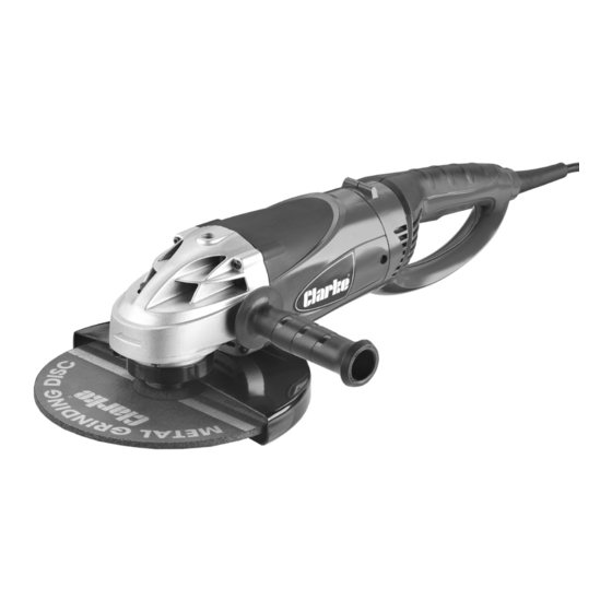
- Page 1 230MM (9”) ANGLE GRINDER MODEL NO: CAG2350 PART NO: 6470098 OPERATION & MAINTENANCE INSTRUCTIONS LS0414...
-
Page 2: Environmental Recycling Policy
INTRODUCTION Thank you for purchasing this CLARKE 230mm (9”) Angle Grinder. Before attempting to use this product, please read this manual thoroughly and follow the instructions carefully. In doing so you will ensure the safety of yourself and that of others around you, and you can look forward to your purchase giving you long and satisfactory service. -
Page 3: General Safety Rules
GENERAL SAFETY RULES 1) WORK AREA 1. Keep the work area clean and well lit. Cluttered and dark areas invite accidents. 2. Do not operate power tools in explosive atmospheres, such as in the presence of flammable liquids, gases or dust. Power tools create sparks which may ignite the dust or fumes. -
Page 4: Angle Grinder Safety Instructions
4) POWER TOOL USE AND CARE 1. Do not force the power tool. Use the correct power tool for your application. The correct power tool will do the job better and safer at the rate which it was designed. 2. Do not use the power tool if the switch does not turn it on and off. Any power tool that cannot be controlled with the switch is dangerous and must be repaired. - Page 5 5. Start up speed. Always allow the angle grinder to run up to full operating speed before applying it to the job. 6. Avoid operator fatigue. Stop the angle grinder at regular intervals for a short break to rest hands and arms. 7.
-
Page 6: Disc Safety Instructions
DISC SAFETY INSTRUCTIONS 1. Disc speed. Check the speed of the disc before fitting to your angle grinder. Never use a disc with a rpm speed less than the rpm speed of your angle grinder. 2. Inspect the disc before fitting. Never use a disc that is chipped, cracked or damaged. -
Page 7: Safety Symbols
SAFETY SYMBOLS Wear ear protection Wear eye protection Not suitable for wet grinding Read instruction manual before use... -
Page 8: Electrical Connections
ELECTRICAL CONNECTIONS WARNING! Read these electrical safety instructions thoroughly before connecting the product to the mains supply. Before switching the product on, make sure that the voltage of your electricity supply is the same as that indicated on the rating plate. This product is designed to operate on 230VAC 50Hz. - Page 9 OVERVIEW DESCRIPTION NO DESCRIPTION Lock Off Lever Threaded hole (for the side handle) On/Off Trigger Switch Rear Handle Disc Guard Mains Lead Grinding/Cutting Disc Air Vents Direction of Rotation Indicator Side Handle Spindle Lock Button Rear Handle Release...
-
Page 10: Before Use
BEFORE USE FITTING / ADJUSTING THE DISC GUARD WARNING: MAKE SURE THAT THE ANGLE GRINDER IS SWITCHED OFF AND UNPLUGGED FROM THE MAINS SUPPLY BEFORE FITTING OR REMOVING ANY ACCESSORIES. 1. Slide the disc guard into place as shown. 2. Rotate the disc guard to the required position and secure by tightening the cap head screw using the hexagonal key supplied. -
Page 11: Fitting And Removing A Disc
FITTING AND REMOVING A DISC WARNING: MAKE SURE THAT THE ANGLE GRINDER IS SWITCHED OFF AND UNPLUGGED FROM THE MAINS SUPPLY BEFORE FITTING OR REMOVING ANY ACCESSORIES. 1. Make sure the disc guard is fitted before you fit any cutting/grinding disc. 2. -
Page 12: Fitting The Side Handle
FITTING THE SIDE HANDLE 1. Fit the side handle by screwing it into one of the 3 threaded holes on the angle grinder. ADJUSTING THE REAR HANDLE The rear handle can be rotated to give a more comfortable grip. 1. Push and hold the rear handle release backwards with one hand. -
Page 13: Using Your Angle Grinder
USING YOUR ANGLE GRINDER WARNING: FRAGMENTS FROM A BROKEN/DETACHED DISC CAN CAUSE SERIOUS INJURY. WARNING: WHEN USING CUTTING DISCS, DO NOT STAND DIRECTLY IN LINE WITH THE ROTATING DISC. WARNING: DO NOT PUT SIDEWAYS PRESSURE ON CUTTING DISCS. WARNING: ENSURE THAT THE WORKING POSITION ADOPTED DOES NOT CAUSE OPERATOR FATIGUE WHICH MAY LEAD TO LOSS OF CONTROL OF THE CUTTING DISC AND IMPACT/SNATCH WITH SURROUNDING OBJECTS/ MATERIALS. -
Page 14: Cutting Tips
CUTTING TIPS • Do not force the disc through the material. Work with a feed rate that is suited to the material being cut. • Do not subject the cutting disc to sideways pressure. • The direction of the cutting motion is important. Always feed the cutting disc into the work so that it cuts in an upward direction. -
Page 15: Changing The Carbon Brushes
MAINTENANCE CHANGING THE CARBON BRUSHES 1. Remove the screw holding the brush cover in place. 2. Remove the worn brush. 3. Replace with the new brush supplied. 4. Repeat on the other side of the body. • Both brushes must be replaced at the same time CLEANING •... -
Page 16: Specifications
PARTS AND SERVICING There are no user serviceable parts in this angle grinder, all servicing and repairs should be carried out by your nearest Clarke dealer. For Parts & Servicing, please contact your nearest dealer, or CLARKE International, on one of the following numbers. - Page 17 OVERVIEW...
-
Page 18: Parts List
PARTS LIST DESCRIPTION PART NUMBER DESCRIPTION PART NUMBER Outer Flange WGCAG235001 33 Rotor WGCAG235033 Grinding Disk WGCAG235002 34 Barrel Head Screw WGCAG235034 Inner Flange WGCAG235003 35 Stator Pressure Plate WGCAG235035 Hexagon Socket Head Bolts WGCAG235004 36 Stator WGCAG235036 Guard WGCAG235005 37 Bearing WGCAG235037 Guard Screw... -
Page 19: Declaration Of Conformity
DECLARATION OF CONFORMITY...
Need help?
Do you have a question about the CAG2350 and is the answer not in the manual?
Questions and answers