Table of Contents
Advertisement
Quick Links
Advertisement
Table of Contents

Subscribe to Our Youtube Channel
Related Manuals for Eaton Powerware Environmental Rack Monitor


Summary of Contents for Eaton Powerware Environmental Rack Monitor
- Page 1 Powerware Environmental Rack Monitor ® User’s Guide...
- Page 2 Powerware is a registered trademark of Eaton Electrical Inc. Microsoft and Windows are registered trademarks of Microsoft Corporation. ECopyright 2007 Eaton Corporation, Raleigh, NC, USA. All rights reserved. No part of this document may be reproduced in any way without the express written approval of Eaton Corporation.
- Page 3 92/31/EEC, Amending Directive 89/336/EEC relating to EMC The EC Declaration of Conformity is available upon request for products with a CE mark. For copies of the EC Declaration of Conformity, contact: Eaton Power Quality Oy Koskelontie 13 FIN-02920 Espoo Finland...
-
Page 4: Table Of Contents
............... ® EATON Powerware Environmental Rack Monitor (ERM) User’s Guide... - Page 5 ........... ® EATON Powerware Environmental Rack Monitor (ERM) User’s Guide...
-
Page 6: Introduction
For more detailed information that is not included in this manual, first register your product at warranty.powerware.com, then visit our Web site: www.powerware.com/rackmonitor. You can also download firmware upgrades, the latest manuals, and other documentation. ® EATON Powerware Environmental Rack Monitor (ERM) User’s Guide 164201673 Rev 1... -
Page 7: Safety Warnings
Environmental Rack Monitor. Before plugging the Environmental Rack Monitor power adapter in, verify that the rating of the power source is matched with the rating of the power adapter. ® EATON Powerware Environmental Rack Monitor (ERM) User’s Guide 164201673 Rev 1... -
Page 8: Installation
Pins 3 and 4 (as labeled to show device 1 and 2). Contact closure devices may be normally open or normally closed. Pin 1 Figure 1. TH-Module Screw Terminal ® EATON Powerware Environmental Rack Monitor (ERM) User’s Guide 164201673 Rev 1... - Page 9 Cable Clamp Figure 2. Cable Clamp Plug the other end of the power cord into a power outlet. Continue to “Configuration” on page 5 to configure the ERM. ® EATON Powerware Environmental Rack Monitor (ERM) User’s Guide 164201673 Rev 1...
-
Page 10: Configuration
Connect the other end of the serial cable to the COM port on the PC. Connect an active Ethernet cable (supplied) to the network connector on the ERM. ® EATON Powerware Environmental Rack Monitor (ERM) User’s Guide 164201673 Rev 1... - Page 11 CONFIGURATION RESET NETWORK TH-Module-1 TH-Module-2 12 VDC To LAN port To PC To Power Outlet Input Contact Sensor (optional) TH-Module Figure 3. Typical ERM Installation ® EATON Powerware Environmental Rack Monitor (ERM) User’s Guide 164201673 Rev 1...
-
Page 12: Configure The Erm
Open your terminal emulation program (such as HyperTerminal). See Figure 4. Figure 4. Accessing HyperTerminal Enter a name and choose an icon for the connection (see Figure 5). ® EATON Powerware Environmental Rack Monitor (ERM) User’s Guide 164201673 Rev 1... - Page 13 CONFIGURATION Figure 5. New Connection Screen Select direct COM port connection (see Figure 6). Figure 6. Select Direct to COM Port Connection ® EATON Powerware Environmental Rack Monitor (ERM) User’s Guide 164201673 Rev 1...
- Page 14 Verify that your terminal program is on the correct communication port for the serial connection. Verify that the ERM has power (one or more LEDs on the ERM are illuminated). The ERM should be turned on. ® EATON Powerware Environmental Rack Monitor (ERM) User’s Guide 164201673 Rev 1...
- Page 15 3. Access Control Table 4. Trap Receiver Table 5. Reset Configuration To Default 6. Restart Rack Monitor 0. Exit Please Enter Your Choice => _ Figure 8. ERM Configuration Menu ® EATON Powerware Environmental Rack Monitor (ERM) User’s Guide 164201673 Rev 1...
-
Page 16: Configure The System Group Parameters
NOTE To complete the ERM configuration, continue to the following section, “Modify the Control Group Parameters” on page 13 or connect the ERM through a Web browser (see page 22). ® EATON Powerware Environmental Rack Monitor (ERM) User’s Guide 164201673 Rev 1... - Page 17 Table 2. System Group Parameters Number Function Description Example/Remark IP Address The ERM IP address. 192.168.1.100 Gateway Address The network default gateway. 192.168.1.254 Network Mask The sub-net mask setting. 255.255.255.0 ® EATON Powerware Environmental Rack Monitor (ERM) User’s Guide 164201673 Rev 1...
-
Page 18: Modify The Control Group Parameters
0. Return to previous menu Please Enter Your Choice => 2 +============================================================================+ [ Control Group Configuration Menu ] +============================================================================+ 1. HTTP Login Username : EATON 2. Community Read-Only : public 3. Community Read/Write : * 4. BOOTP/DHCP Control : Enable 5. - Page 19 Telnet Control Enable/disable the TELNET protocol. Enable HTTP Control Enable login and password request for HTTP access. Enable SNMP Control Enable login and password request for SNMP access. Enable ® EATON Powerware Environmental Rack Monitor (ERM) User’s Guide 164201673 Rev 1...
-
Page 20: Modify The Parameter Group Parameters
Alphanumeric string Technical Support Lab Poll Rate The time interval in seconds the ERM update measurement (Temperatures and Humidity) from sensor, valid value is between 3 to 60. ® EATON Powerware Environmental Rack Monitor (ERM) User’s Guide 164201673 Rev 1... -
Page 21: Configure The Email Group Parameters
4. DNS IP Address : 0.0.0.0 5. Mail Receivers 6. Test Email Configuration 0. Return to previous menu Please Enter Your Choice => 0 Figure 13. Email Group Configuration Menu ® EATON Powerware Environmental Rack Monitor (ERM) User’s Guide 164201673 Rev 1... - Page 22 As Administrator, you are required to enter the IP address of your network DNS server if you entered a Hostname for the Mail Server. Otherwise, this field will contain 0.0.0.0. ® EATON Powerware Environmental Rack Monitor (ERM) User’s Guide 164201673 Rev 1...
-
Page 23: Set The Th-Module Configuration
1. TH-Module-1 Status : Auto 2. TH-Module-1 Name : Lab Door Sensor 0. Return to previous menu Please Enter Your Choice => _ Figure 15. TH-Module-1 Setup Screen ® EATON Powerware Environmental Rack Monitor (ERM) User’s Guide 164201673 Rev 1... -
Page 24: Configure The Access Control Table
NOTE If a “NotAccess” access right is associated with an IP address, the associate workstation will not be able to display any information regarding the ERM, even if the Community Read-Only string is entered. ® EATON Powerware Environmental Rack Monitor (ERM) User’s Guide 164201673 Rev 1... -
Page 25: Set Trap Receivers
Type 2 on the Trap Receiver Table screen to reset an entry to the default setting. Type 0 to return to the Main Menu. NOTE The Set Trap Receivers configuration is used only for SNMP Network Manager. ® EATON Powerware Environmental Rack Monitor (ERM) User’s Guide 164201673 Rev 1... -
Page 26: Complete Erm Configuration
At this point, the initial ERM configuration is complete. NOTE If you want to restore the default ERM configuration data set in the factory, type ® EATON Powerware Environmental Rack Monitor (ERM) User’s Guide 164201673 Rev 1... -
Page 27: Configuration Through A Telnet Connection
10BaseT hub port (see Figure 3 on page 6). Verify that both DIP switches on the ERM are set to the 0 (off) position (see Figure 3 on page 6). ® EATON Powerware Environmental Rack Monitor (ERM) User’s Guide 164201673 Rev 1... -
Page 28: Setup The Ip Address
Enter the URL http:\\172.17.XXX.ZZZ in the address box (where XXX and ZZZ is the last two pairs of the MAC address of the ERM in decimal). The ERM home page displays (see Figure 19). ® EATON Powerware Environmental Rack Monitor (ERM) User’s Guide 164201673 Rev 1... -
Page 29: Initial Configuration
(see Figure 20). Click the Become Administrator button at the bottom of the screen. Enter EATON as the login name and admin as the password. Enter the ERM IP address. Enter the ERM Gateway Address in the network. - Page 30 CONFIGURATION Figure 20. Rack Monitor Configuration Screen Figure 21. Rack Monitor Control Screen ® EATON Powerware Environmental Rack Monitor (ERM) User’s Guide 164201673 Rev 1...
-
Page 31: Erm Management
ERM Monitoring The main menu contains all the measurements and data read from the ERM. All the sub-menus are read-only for all users; write-mode access is not allowed. EATON Powerware ® Environmental Rack Monitor (ERM) User’s Guide 164201673 Rev 1... -
Page 32: Comprehensive View
Figure 22. Comprehensive View Screen Detail Data This page gives the detail information of all parameters. This page refreshes automatically every five seconds. Figure 23. Detail Data Screen ® EATON Powerware Environmental Rack Monitor (ERM) User’s Guide 164201673 Rev 1... -
Page 33: Th-Module-1 Setup
This page lets the user configure all necessary parameters of the TH-Module-1. Figure 24. TH-Module-1 Setup Screen TH-Module-2 Setup (optional) This page lets the user configure all necessary parameters of the optional TH-Module-2. Figure 25. TH-Module-2 Setup Screen ® EATON Powerware Environmental Rack Monitor (ERM) User’s Guide 164201673 Rev 1... -
Page 34: Rack Monitor Identification
This menu contains the control parameters of the TH-Module connected to the ERM. All the sub-menus are available in read-only for all users. Only the administrator has access in read/write mode. ® EATON Powerware Environmental Rack Monitor (ERM) User’s Guide 164201673 Rev 1... -
Page 35: Date And Time
This page lets you manually set the ERM internal date and time. Figure 28. Date and Time Screen ERM Configuration This page lets the Administrator set the local network configuration parameters for the ERM. Figure 29. ERM Configuration Screen ® EATON Powerware Environmental Rack Monitor (ERM) User’s Guide 164201673 Rev 1... -
Page 36: Erm Control
Read/Write Access Type to login, only allowing modification of the ERM parameters and Access Type, to prevent someone arbitrarily from changing it unless they login with the Admin password. ® EATON Powerware Environmental Rack Monitor (ERM) User’s Guide 164201673 Rev 1... -
Page 37: Trap Receivers
This page can hold a maximum of four entries. It holds the list of the IP address of the Network Management Stations (NMS), which will receive the SNMP traps sent by the ERM. Figure 32. SNMP TRAP Receivers Screen ® EATON Powerware Environmental Rack Monitor (ERM) User’s Guide 164201673 Rev 1... -
Page 38: Email Notification
Web page that users can easily connect to related Web pages. Figure 34. External Links Screen ® EATON Powerware Environmental Rack Monitor (ERM) User’s Guide 164201673 Rev 1... -
Page 39: Erm History
NOTE To save the History Log to a file in Microsoft Excel format, go to the Clear/Save sub-menu and click on History Log under the Save Log Data title bar. Figure 35. History Log Data Screen ® EATON Powerware Environmental Rack Monitor (ERM) User’s Guide 164201673 Rev 1... -
Page 40: Extended Log
Extended Log Interval in the ERM Configuration page. The existing log is overwritten when the maximum numbers of entries are reached. Figure 36. Extended Log Data Screen ® EATON Powerware Environmental Rack Monitor (ERM) User’s Guide 164201673 Rev 1... -
Page 41: Sensor Events
This page lists all the events that have occurred since the table was cleared. The existing values are overwritten when the maximum number of entries (rows) has been reached. Figure 37. Sensor Events Screen ® EATON Powerware Environmental Rack Monitor (ERM) User’s Guide 164201673 Rev 1... -
Page 42: Erm Events
NOTE When you select any of the hyper-links here while the ”Clear the corresponding log data as you click the hyper-link below” selection is set to “Yes”, the corresponding log data will be lost even if you cancel the operation. ® EATON Powerware Environmental Rack Monitor (ERM) User’s Guide 164201673 Rev 1... - Page 43 ERM MANAGEMENT Figure 39. Clear & Save Log Data Screen ® EATON Powerware Environmental Rack Monitor (ERM) User’s Guide 164201673 Rev 1...
-
Page 44: Monitoring
Click the Refresh button after configuring any setting on the TH-Module History Log Monitor for the change to take effect. Reload Update the TH-Module History Log Monitor and reset the right display margin. Exit Close the TH-Module History Log Monitor window. ® EATON Powerware Environmental Rack Monitor (ERM) User’s Guide 164201673 Rev 1... -
Page 45: Extended History Log Monitor
Monitor for the change to take effect. Reload Update the TH-Module Extended History Log Monitor and reset the right display margin. Exit Close the TH-Module Extended History Log Monitor window. ® EATON Powerware Environmental Rack Monitor (ERM) User’s Guide 164201673 Rev 1... -
Page 46: Managing Erm Via Snmp
(default is admin) for the SET community string. GET Community string: public SET Community string: admin For more information, see the MIB file on the ERM CD. ® EATON Powerware Environmental Rack Monitor (ERM) User’s Guide 164201673 Rev 1... -
Page 47: Appendix
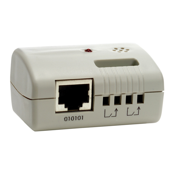
Warranty ERM Panel Details Front Panel Status Power Environmental Rack Monitor DIP Switch Power Inlet Rear Panel RESET NETWORK TH-Module-1 TH-Module-2 12 VDC Figure 42. ERM Panel Details EATON Powerware ® Environmental Rack Monitor (ERM) User’s Guide 164201673 Rev 1... -
Page 48: Led Description
Power LED ERM Function Description — Power on Flashing — TH-Module activity Flashing Serial upgrade mode Two LEDs Cross Flashing Two LEDs Cross Flashing Auto diagnostic mode Hardware error ® EATON Powerware Environmental Rack Monitor (ERM) User’s Guide 164201673 Rev 1... -
Page 49: Technical Specifications
DIP Switch Description DIP switch definitions for the ERM are listed in Table 11. Table 11. DIP Switch Modes Description Manufacture diagnostic mode Serial upgrade mode Reserved Operating mode ® EATON Powerware Environmental Rack Monitor (ERM) User’s Guide 164201673 Rev 1... -
Page 50: Serial Cable Definition
Table 13. Cable for the ERM TH-Module-2 Port RJ-45 DB-9 Female Description — Not connected Received data from PC Signal ground Case GND Chassis ground Transmitted data to PC — Not connected ® EATON Powerware Environmental Rack Monitor (ERM) User’s Guide 164201673 Rev 1... -
Page 51: Upgrading The Erm Firmware
ERM CD). This program is compatible with Windows 95/98/Me, Windows NT 3.51/4.0/2000/XP and higher. NOTE You can simultaneously upgrade up to four ERMs on the network using the EMPupgrade.exe program. Figure 43. Upgrade Utility Screen ® EATON Powerware Environmental Rack Monitor (ERM) User’s Guide 164201673 Rev 1... - Page 52 Sends the program loaded with the Open button to the selected ERM of the ERM List. Open Open and load the new image file for upgrade. Quit Exit the program. ® EATON Powerware Environmental Rack Monitor (ERM) User’s Guide 164201673 Rev 1...
- Page 53 *1642016731* 164201673 1...
Need help?
Do you have a question about the Powerware Environmental Rack Monitor and is the answer not in the manual?
Questions and answers