Table of Contents
Advertisement
Quick Links
Advertisement
Table of Contents

Subscribe to Our Youtube Channel
Summary of Contents for Eaton SONiX Pm10
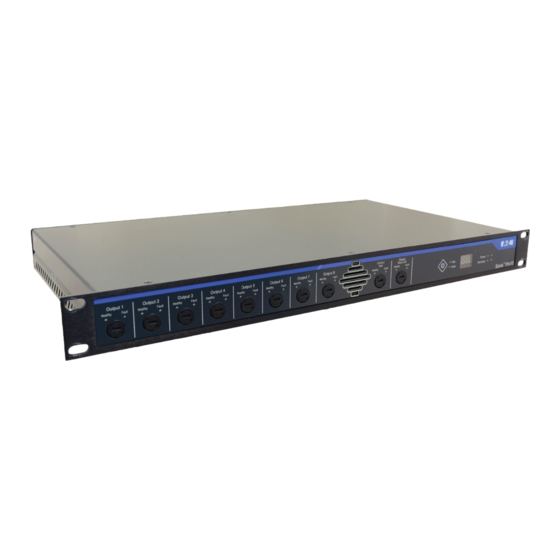
- Page 1 SONIX Pm10 Technical Manual SONIX Pm10 Power Management Unit...
- Page 2 CONTRACT BETWEEN THE PARTIES. In no event will Eaton be responsible to the purchaser or user in contract, in tort (including negligence), strict liability or other-wise for any special, indirect, incidental or consequential damage or loss whatsoever, including but not limited to...
- Page 3 Beacon Bus A 2Mx bus, used to communicate with and control Sonix Vw2 units Power Bus A 2Mx bus, used to communicate with and control Sonix Pm10 units Global Bus A 2Mx bus, used to communicate with SAS application Sync A 2Mx bus used to communicate with the second 2Mx unit when PA/GA system is confi gured as A&B, AB+ or N+1...
-
Page 4: Table Of Contents
9 MAINTENANCE . . . . . . . . . . . . . . . . . . . . . . . . . . . . . . . . . . . . . . . . . . . . . . . . . . . . . . . . . . . . . . . . . . . . . . . 18 SONIX PM10 TECHNICAL MANUAL TM365-2 / A June 2022 www.eaton.com... - Page 5 FIGURE 1 . GENERAL, SIMPLIFIED VIEW OF THE SONIX PM10 FRONT PANEL . . . . . . . . . . . . . . .
-
Page 6: Introduction
1.2 About the product manner. Sonix Pm10 is a compact 19” 1U design unit, housing 2.2 Safe working practice the circuitry for power distribution, switchover and Whilst working on or within the Sonix PA/GA system it management for the Sonix PA/GA system components. -
Page 7: Unit Overview
Healthy Fault Healthy Fault Primary Volts Secondary Amps Sonix Pm10 Warning: Dangerous voltages. Do not open Figure 1. General, simplified view of the Sonix Pm10 front panel. COMPLIANT Power Bus Primary Supply Secondary Supply Item Description O/P 8 O/P 7... -
Page 8: Installation And Connectivity
Warning: Unit must be connected to protective 48VDC 48VDC Fault output N/O COM N/C earth observing minimum cable requirements. IEC 60417-6043 (2011-01) Beware of sharp edges and corners! Take care while handling. SONIX PM10 TECHNICAL MANUAL TM365-2 / A June 2022 www.eaton.com... -
Page 9: Power Bus
Pm10. In the event of either one of those cables becoming disconnected or otherwise broken data has The Sonix Pm10 is designed as a part of Sonix PA/GA a redundant path, ensuring the system will continue to system and as such, bulk of the unit’s connections are... -
Page 10: Ac Power Input
Protective Earth bar Incoming power supply 110 V ac 230 v ac Incoming power supply 110 V ac 230 v ac Figure 8. Pm10 powered from two redundant power supplies. SONIX PM10 TECHNICAL MANUAL TM365-2 / A June 2022 www.eaton.com... -
Page 11: Figure 9. Pm10 Powered From A Single Power Supply
As these cables are power feeds, they should be, where pos- connections. sible, routed within the PA/GA system in a separate way to avoid contact with dc power or audio cables and reduce the possibility of interference. SONIX PM10 TECHNICAL MANUAL TM365-2 / A June 2022 www.eaton.com... -
Page 12: Ac Power Output
N/O COM N/C COMPLIANT Primary Supply Secondary Supply O/P 8 O/P 7 O/P 6 O/P 5 O/P 4 O/P 3 Warning: Observe the polarity / order of Figure 11. Auxiliary output connections. SONIX PM10 TECHNICAL MANUAL TM365-2 / A June 2022 www.eaton.com... -
Page 13: Dc Power Distribution
1.5 mm • with ac power or audio cables and reduce the possibility of interfer- Stranded: ence. • including sleeved ferrule: 0.5 mm • including non-sleeved ferrule: 1.5 mm • SONIX PM10 TECHNICAL MANUAL TM365-2 / A June 2022 www.eaton.com... -
Page 14: Fault Output
Fault output will hold its state for approximately 10 seconds before clearing after any fault has cleared, to The fault output on the Sonix Pm10 is a volt-free contact allow any transient faults to be registered by any external output. The state of the fault output is determined by monitoring. -
Page 15: Setup And Configuration
If more than one Pm10 unit is connected, All Pm10 units con- ote: nected to the 2Mx will flash their user selection LEDs, only button press on the unit designated to change its Unit ID. SONIX PM10 TECHNICAL MANUAL TM365-2 / A June 2022 www.eaton.com... -
Page 16: Unit Operation
6.3 AC Power input status indication Pm10 reports the status of its AC power inputs via pairs Sonix Pm10 operates on the Power bus as a part of the of green and red LEDs grouped with each input (see Sonix PA/GA system. The Sonix 2Mx central controller... -
Page 17: Auxiliary Output
Sonix units that are dc powered, such as Hmi or Vw2. The Pm10 reports the status of the DC Rack Output via a pair of green and red LEDs (see Figure 1), as per table below: SONIX PM10 TECHNICAL MANUAL TM365-2 / A June 2022 www.eaton.com... -
Page 18: Unit Customisation
Remove dust and dirt from front panel - clean with a • dry cloth. ote: Do not use sharp objects. Do not use water, aggressive cleaning agents or solvent to clean the unit. SONIX PM10 TECHNICAL MANUAL TM365-2 / A June 2022 www.eaton.com... - Page 19 All specifications, dimensions, weights and tolerances are nominal (typical) T: +44 (0) 1623 444 400 Printed in UK www.crouse-hinds.com/hac Publication No.TM365-2 / A and Eaton reserve the right to vary all data without prior notice. No liability is accepted for any consequence of use. MEDCSales@Eaton.com June 2022...


Need help?
Do you have a question about the SONiX Pm10 and is the answer not in the manual?
Questions and answers