Panasonic MICRO-IMAGECHECKER A200 Series Hardware Manual
Machine vision system
Hide thumbs
Also See for MICRO-IMAGECHECKER A200 Series:
- Operating instructions manual (66 pages) ,
- Operating instructions manual (101 pages) ,
- Hardware manual (105 pages)
Table of Contents
Advertisement
Advertisement
Table of Contents

Related Manuals for Panasonic MICRO-IMAGECHECKER A200 Series


Summary of Contents for Panasonic MICRO-IMAGECHECKER A200 Series
- Page 2 WARNINGS AND CAUTIONS To be observed at all times Read the manual carefully before installing, running, maintaining or inspecting the equipment. This manual uses two safety flags to indicate different levels of danger. WARNING If critical situations that could lead to user’s death or serious injury are assumed by mishandling of the product: −...
- Page 3 GENERAL INSTRUCTIONS Installation Environment Avoid using the Micro−Imagechecker A210/A110 in the following types of locations: − Locations with direct sunlight or environmental temperatures that exceed a range of 0°C to 50°C. − Locations with a relative humidity exceeding a range of 35%RH to 75%RH or that are subject to condensation due to dramatic temperature fluctuations.
- Page 4 See User’s Manual for more information about initialization. Other Instructions − Use monitor, monitor cable, keypad, camera and camera cable models and serial numbers specified by Panasonic Electric Works Co., Ltd. − Do not disassemble, modify, or change internal settings for the Micro−Imagechecker unit or other equipment.
-
Page 6: Table Of Contents
Contents Chapter 1 Part Names and Functions Controller ............1 −... - Page 7 Contents A200/A100 Hardware Chapter 4 Serial (RS−232C) Ports Serial (RS−232C) Ports ..........4 −...
- Page 8 A200/A100 Hardware Contents Chapter 8 Part Numbers Controllers ............8 −...
- Page 9 Contents A200/A100 Hardware...
- Page 10 Chapter 1 Part Names and Functions Controller ........1 −...
- Page 11 Part Names and Functions A200/A100 Hardware 1 − 2...
-
Page 12: Controller
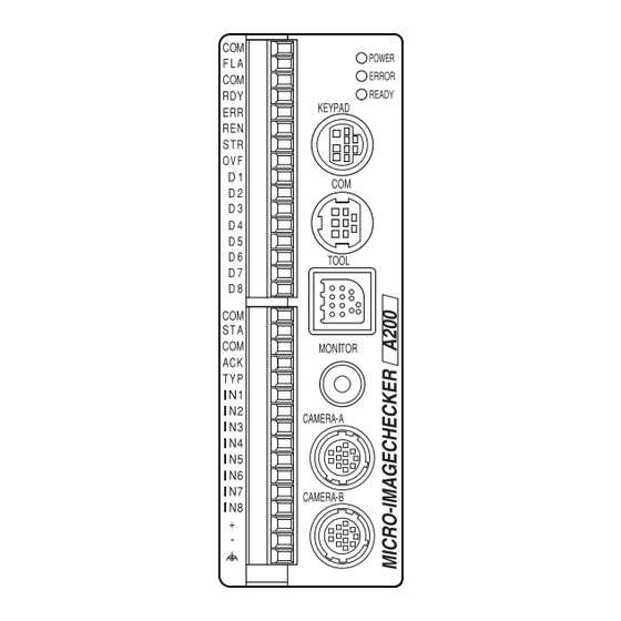
A200/A100 Hardware Part Names and Functions Controller Controller Weight: Around 300g A100 A200 Size: 40 × 120 × 50mm (Excluding protruding parts) Names and Functions of Controller Parts Operating LEDs Indicate the controller’s operating status. POWER (green) This green LED is lit when the controller is connected to a live power source. - Page 13 Part Names and Functions A200/A100 Hardware Controller Power supply 24 power is required. The power supply is connected to the input terminal block. External input terminal (16 pin) Provides a connection for input from an external source. External output terminal (16 pin) Provides a connection for output to an external device.
-
Page 14: A Series Camera
A200/A100 Hardware Part Names and Functions A Series Camera A Series Camera 1.2.1 Double−Speed Random Camera Weight: around 70g (camera only) Size: 29 × 31 × 54.5mm (Excluding protruding parts) Names and Functions of Double−Speed Random Camera Parts Camera The camera body. Lens mount A C−mount. - Page 15 Part Names and Functions A200/A100 Hardware A Series Camera About the DIP Switches − Gain adjustment DIP switch 5: ON = 0 to +10dB range gain adjustment volume. OFF = 0dB − Potentiometer: When DIP−SW5 is ON, turning this potentiometer to the right increases the brightness of the image captured by the camera.
-
Page 16: Cs−Mount Camera
A200/A100 Hardware Part Names and Functions A Series Camera 1.2.2 CS−Mount Camera CS−Mount Camera: Part Names and Functions 1. Camera The camera’s main unit. 2. Lens mount A CS−mount. 3. Lens Use the C/CS−mount lens together with an adapter ring as necessary. Select a lens from the Field of Vision and Lens Selection Table on page 2 −... -
Page 17: Camera Cable And Camera Extension Cable
Part Names and Functions A200/A100 Hardware Camera Cable and Camera Extension Cable Camera Cable and Camera Extension Cable Names and Functions of Parts 1. Connector (male): Connects the male connector to the controller. 2. Connector (female): Connects the female connector to the camera. Using the Cable Correctly −... -
Page 18: Keypad
A200/A100 Hardware Part Names and Functions Keypad Keypad 2, 3 ENTER Names and Functions of Parts 1. A, B, C buttons Can be operated using function displayed on the screen. 2. Cursor lever Moves the cursor. Can move it in a maximum of eight directions. 3. - Page 19 Part Names and Functions A200/A100 Hardware Keypad 1 − 10...
- Page 20 Chapter 2 Installation and Wiring Connecting Peripherals ......2− 3 Installation Environment and Mounting Space .
- Page 21 Installation and Wiring A200/A100 Hardware 2 − 2...
-
Page 22: Chapter 2 Installation And Wiring
A200/A100 Hardware Installation and Wiring Connecting Peripherals Connecting Peripherals Be sure to connect peripherals to the controller only when the controller power is OFF. Keypad Monitor−Cable 24 V DC Ground Camera−Cable *Only one camera can be connected to the A100. Using Peripherals Correctly −... -
Page 23: Installation Environment And Mounting Space
Installation and Wiring A200/A100 Hardware Installation Environment and Mounting Space Installation Environment and Mounting Space Avoid Installing the Equipment in Locations with the Following Characteristics − Where the temperature is outside the range of 0°C to 50°C. − Where the relative humidity is outside the range of 35%RH to 75%RH. −... - Page 24 A200/A100 Hardware Installation and Wiring Installation Environment and Mounting Space Heat Dissipation − Mount the unit in any of the following arrangements to facilitate heat dissipation. Contact mounting is acceptable. Do not mount the unit on top of strong heat sources such as heaters, transformers, or high−capacity resistors.
-
Page 25: Mounting The Controller
Installation and Wiring A200/A100 Hardware Mounting the Controller Mounting the Controller You can mount the controller either by using screws or by hooking it on a DIN rail. Mounting the Controller on a DIN Rail The controller can be mounted on or removed from a 35mm wide DIN rail (DIN EN50022) by a single easy motion. -
Page 26: Mounting The Camera
A200/A100 Hardware Installation and Wiring Mounting the Camera Mounting the Camera Mount the camera so it doesn’t wobble. You can mount the camera directly or with metal fitting. Use the dimensional diagram for reference when you mount the camera. Using the Camera Correctly −... -
Page 27: View Range And Lens Selection Tables
Installation and Wiring A200/A100 Hardware View range and Lens Selection Tables View range and Lens Selection Tables Select the lens and extension rings from the following table in order to match the resolution or view range. 2.5.1 ANM831 Double−Speed Random Camera Lens ANB846NL ANB845NL... -
Page 28: Anm832 Standard Camera
A200/A100 Hardware Installation and Wiring View range and Lens Selection Tables 2.5.2 ANM832 Standard Camera Lens ANB846NL ANB845NL ANM8850 (1) ANB847L ANB843L Resolution (*1) ANM88251 ANM88161 f=50mm f=50mm f=8.5mm µm/pixel f=25mm f=16mm View range (mm) Vertical Horizontal view view Vertical Horizontal range range 10.4... - Page 29 Installation and Wiring A200/A100 Hardware View range and Lens Selection Tables Lens ANB842L ANM8808 (1) ANM8804 (1) ANM8828 (1) Resolution f=6.5mm f=8mm f=4mm f=2.8mm µm/pixel View range (mm) Vertical Horizontal view view Vertical Horizontal range range 10.4 10.4 15.6 15.6 10.7 20.8 20.9...
- Page 30 Chapter 3 Input/Output Terminals (Input/Output Ports) Attaching Wires to the Terminal Blocks ... . . 3 − 3 Output Terminal (Parallel Output Port) ....3 −...
- Page 31 Input/Output Terminals (Input/Output Ports) A200/A100 Hardware 3 − 2...
-
Page 32: Chapter 3 Input/Output Terminals (Input/Output Ports)
The I/O terminal block plugs into the controller, and the terminals are fastened by tightening the screws. Use the fittings and cable listed in the tables below. Terminal block socket Manufacturer Part contact model number Panasonic Electric Works Co., Ltd. ANMA8001 Phoenix Contact Model number Part order number MC1.5/16−ST−3.5 1840502 Screw−on fittings... -
Page 33: Output Terminal (Parallel Output Port)
Input/Output Terminals (Input/Output Ports) A200/A100 Hardware Output Terminal (Parallel Output Port) Output Terminal (Parallel Output Port) Terminal Positions Signal Name Content COMMON Common flash dedicated line FLASH Flash sync signal COMMON General output common READY Ready signal ERROR Error signal READ END Image capture complete signal STROB... -
Page 34: Input Terminal (Parallel Input Port)
A200/A100 Hardware Input/Output Terminals (Input/Output Ports) Input Terminal (Parallel Input Port) Input Terminal (Parallel Input Port) Terminal Positions Signal Name Content COMMON START common START Inspection start signal COMMON COMMON, other than START input ACKNOWLEDGE Data receiving complete signal TYPE Product type switched signal Data input Data input... -
Page 35: Cautions Related To Parallel Input/Output
Input/Output Terminals (Input/Output Ports) A200/A100 Hardware Cautions Related to Parallel Input/Output Cautions Related to Parallel Input/Output The input/output ports are housed in the particular controller being used. The ports differ according to the inspection specifications. See the individual controller’s user manual for details. -
Page 36: About Parallel Input
A200/A100 Hardware Input/Output Terminals (Input/Output Ports) Cautions Related to Parallel Input/Output 3.4.2 About Parallel Input − The controller accepts ( ) common. To prevent input signal chattering, use a ± non−contact input (transistor etc.). If chattering occurs, inputs can be missed, and input recognition delayed. -
Page 37: Flash Output Sync Signal
Input/Output Terminals (Input/Output Ports) A200/A100 Hardware Flash Output Sync Signal Flash Output Sync Signal Terminal Positions COM: The flash terminal is located in the output terminal. FLASH FLASH: The common terminal for use by the flash is a specialized terminal. Do not use it together with other common lines. - Page 38 A200/A100 Hardware Input/Output Terminals (Input/Output Ports) Flash Output Sync Signal Using the Flash Output Sync Signal Correctly − The flash’s common wire uses a specialized terminal. Do not use it together with another common wire. − You cannot use the same strobe for multiple cameras connected to separate controllers.
-
Page 39: Electric Power Wiring
Input/Output Terminals (Input/Output Ports) A200/A100 Hardware Electric Power Wiring Electric Power Wiring Terminal Positions 24 V DC electric power is supplied by attach- ing wires to the input terminal block’s (+) and (–) terminals and to the ground terminal (frame ground). - Page 40 A200/A100 Hardware Input/Output Terminals (Input/Output Ports) Electric Power Wiring Increase Resistance to Noise − Separate the systems for wiring to the controller, input devices, and output devices. − When there is a particular concern about noise coming from input/output circuits, supply power to the controller and to the input/output devices separately.
-
Page 41: About Grounding
Input/Output Terminals (Input/Output Ports) A200/A100 Hardware About Grounding About Grounding Attaching a Ground to Prevent Effects of Noise − The controller can tolerate the noise present in a normal environment. Provide a ground when installing it in a particularly noisy environment. Use a Dedicated Ground Wire −... -
Page 42: Chapter 4 Serial (Rs−232C) Ports
Chapter 4 Serial (RS−232C) Ports Serial (RS−232C) Ports ......4− 3 COM port (Data output, VBT Ver. 2) . - Page 43 Serial (RS−232C) Ports A200/A100 Hardware 4 − 2...
-
Page 44: Serial (Rs−232C) Ports
A200/A100 Hardware Serial (RS−232C) Ports Serial (RS−232C) Ports Serial (RS−232C) Ports The controller contains two independent serial ports. The COM port is an 8−pin round connector. It is used for general RS−232C communication. The TOOL port is a square connector. It is used only for connection to VBT Ver. 2. An application stored in the controller determines the commands and parameters such as baud rate and parity used for communication. - Page 45 Serial (RS−232C) Ports A200/A100 Hardware Serial (RS−232C) Ports Examples of RS−232C Connections General−purpose RS−232C and VBT Ver. 2 can be used for the COM port. Only VBT Ver. 2 can be used for the TOOL port. TOOL TOOL Cannot connect For saving and restoring VBT Ver.
-
Page 46: Com Port (Data Output, Vbt Ver. 2)
A200/A100 Hardware Serial (RS−232C) Ports COM port (Data output, VBT Ver. 2) COM port (Data output, VBT Ver. 2) Terminal Positions A Hoshiden−manufactured connector (part no. TCS6180) is used as the COM (RS−232C) port on the controller unit. Controller−side terminal Pin No. - Page 47 Name (to COM port) ANM81303 serial cable White (Length: approx. 3 m) Black Yellow CTS Blue Green GND Brown DCD Gray Panasonic PLC FP series (Computer communication unit) A series Signal Wire Signal color White Black Short Short Yellow –...
- Page 48 A200/A100 Hardware Serial (RS−232C) Ports COM port (Data output, VBT Ver. 2) Example of connection with Mitsubishi PLC Computer Link Communication with Mitsubishi A/Q series supports for “Type 4”. Example 1 Mitsubishi A & Q series(9pins) ICH A series Signal Signal Wire White...
- Page 49 Serial (RS−232C) Ports A200/A100 Hardware COM port (Data output, VBT Ver. 2) Example of connection with Omron PLC Omron: C series Ex. 1 (9 pin) ICHA series Signal Wire Signal color White Black Short Short Yellow Blue – Short – Green –...
- Page 50 A200/A100 Hardware Serial (RS−232C) Ports COM port (Data output, VBT Ver. 2) Example of connection with Allen−Bradley PLC Allen−Bradley: SLC500 ICH A series Signal Wire Signal color White Black Short Yellow Blue Short Green Brown Gray − Cover Shield Cover Shield –...
-
Page 51: Tool Port (Vbt Ver. 2 Port)
Serial (RS−232C) Ports A200/A100 Hardware TOOL port (VBT Ver. 2 Port) TOOL port (VBT Ver. 2 Port) Terminal Positions A Hoshiden−manufactured connector (part no. TCS7729) is used as the TOOL port on the controller unit. Controller−sideterminals Pin No. Signal Name Pin No. - Page 52 R×D Reserved R×D Purple T×D T×D T×D T×D Black Reserved Reserved Brown Green Pink Reserved Reserved Panasonic Electric Works Co., Ltd. R×D MIL connecter Reserved AXM214001 Reserved Brown White Brown Gray Brown Orange Sky blue Brown Blue Brown Br. green...
- Page 53 Serial (RS−232C) Ports A200/A100 Hardware TOOL port (VBT Ver. 2 Port) 4 − 12...
-
Page 54: About Camera Modes
Chapter 5 About Camera Modes Camera Modes ....... . . 5 −... - Page 55 About Camera Modes A200/A100 Hardware 5 − 2...
- Page 56 A200/A100 Hardware About Camera Modes Camera Modes Camera Modes Two of our cameras can be used with the A Series: The double−speed random camera, model ANM831, and the standard camera, model ANM832. The A Series supports a total of six camera modes. The camera mode is set according to whether the inspection object is moving or still, whether the illumination is continuous or strobe, and the camera type.
- Page 57 About Camera Modes A200/A100 Hardware Imaging Time for the Camera Modes (for memory image display) and Resolution Imaging Time for the Camera Modes (for memory image display) and Resolution Frame Field Double−Speed Imaging time = (shutter time) + 16.7ms Imaging time = (shutter time) + 8.3ms Ra do Random Start Trigger...
-
Page 58: Frame Mode And Field Mode
A200/A100 Hardware About Camera Modes Frame Mode and Field Mode Frame Mode and Field Mode Frame Mode In this mode, the camera captures an even number array and an odd number array and sends them to the image processing system. In the A Series, all 512 × 480 pixels are sent to memory and are then subject to image processing. - Page 59 About Camera Modes A200/A100 Hardware Frame Mode and Field Mode 5 − 6...
- Page 60 Chapter 6 Product Type Data Creation and Backup Product Type Data Creation and Backup ... 6− 3...
- Page 61 Optional Memory A200/A100 Hardware 6 − 2...
-
Page 62: Chapter 6 Product Type Data Creation And Backup
A200/A100 Hardware Optional Memory Product Type Data Creation and Backup Product Type Data Creation and Backup Product type data is created with the special−purpose keypad. You can back up the created product type data together with image data stored on the controller to a *Windows PC, then restore the data later. - Page 63 Optional Memory A200/A100 Hardware Product Type Data Creation and Backup 6 − 4...
- Page 64 Chapter 7 General Specifications Controller ........7 −...
- Page 65 General Specifications A200/A100 Hardware 7 − 2...
-
Page 66: Chapter 7 General Specifications
A200/A100 Hardware General Specifications Controller Controller Item Specification 512 × 480 pixels (horizontal × vertical) Processing resolution Processing function Gray scale image/binarized image processing (details are determined by the application) Settings Special−purpose keypad External interface Serial COM port: RS−232C TOOL port: RS−232C Parallel input Removable terminal block Input to 11 positions 12 V to 24 V DC input Bidirectional photocoupler... -
Page 67: Keypad
General Specifications A200/A100 Hardware Keypad Keypad Item Specification Operation bottuns, lever 8−direction lever, used jointly with the ENTER button: 1. A, B, C buttons = 1 each Operating / storage ambient humidity ° RH 35% to 75% (without icing and dew condensation at 25 Operating ambient temperature °... -
Page 68: Monitor
A200/A100 Hardware General Specifications Monitor: ANMA810 Monitor: ANMA810 Item Specification Rated voltage 100 V AC Allowable voltage range 90 to 120 V AC Rated power consumption 30 W or less 9 inch, White Operation frequency Horizontal: 15.734 kHz Vertical: 59.94 Hz Input level 1.0 Vp−p (Video signal: 0.7 Vp−p positive polarity Synchronization signal: negative polarity) -
Page 69: Double−Speed Random Camera Anm831
General Specifications A200/A100 Hardware Double−Speed Random Camera ANM831 Double−Speed Random Camera ANM831 Item Specification Imaging element Readout of all pixels (interline transfer protocol) 1/3 inch CCD fixed photo elements Horizontal 659 pixels × vertical 494 pixels; pixel size = Square Pixel Effective pixels Scanning method Non−interlaced mode (1/60s) -
Page 70: Cs−Mount Camera Anm832
A200/A100 Hardware General Specifications CS−Mount Camera ANM832 CS−Mount Camera ANM832 Item Specification Imaging element Interline transmission method 1/3 inch CCD solid state imaging element 768 pixels (horizontal) × 492 pixels (vertical) Effective pixels Scanning method 2:1 interlace (1/60s) Accumulation Frame accumulation Shutter speed OFF 1/60s, Electronic shutter = 1/100, 1/125, 1/500, 1/1000, 1/2000, 1/4000, and... - Page 71 General Specifications A200/A100 Hardware CS−Mount Camera ANM832 7 − 8...
-
Page 72: Chapter 8 Part Numbers
Chapter 8 Part Numbers Controllers ........8 −... - Page 73 Part Numbers A200/A100 Hardware 8 − 2...
-
Page 74: Controllers
A200/A100 Hardware Part Numbers Controllers Controllers Item Specification Part Number Micro−Imagechecker A200 series Multichecker NPN Output Conformed ANMA210 Initial display : Japanese Includes Japanese manual NPN Output Conformed ANMA212 Initial display : English Includes English manual Photo MOS Output Conformed ANMA218 Initial display : English Includes English manual... - Page 75 Part Numbers A200/A100 Hardware Controllers Item Specification Part Number Micro−Imagechecker A100 series Multichecker NPN Output Conformed ANMA110 Initial display : Japanese Includes Japanese manual NPN Output Conformed ANMA112 Initial display : English Includes English manual Photo MOS Output Conformed ANMA113 Initial display : English No manual Spare Input/Output Terminal...
-
Page 76: Cameras
A200/A100 Hardware Part Numbers Cameras Cameras Item Specification Part Number Double−speed random camera Double−speed random camera Conformed ANM831 CS−mount camera CS−mount camera Not conformed ANM832 ANM83203 Conformed ANM832CE *1) Although ANM83203 is the same specification as ANM832, only the length of a cable has a difference in both. -
Page 77: Double−Speed Random Camera Cable
Part Numbers A200/A100 Hardware Double−Speed Random Camera Cable Double−Speed Random Camera Cable Item Specification Part Number ANM831 camera cable Not conformed ANM84303 3m: CE compliant Conformed ANM84303CE 3m: Durable type Not conformed ANM84603 Use the camera extension cable when extending the double−speed random camera’s cable 3 meters or more. -
Page 78: Camera Extension Cable
A200/A100 Hardware Part Numbers Camera Extension Cable Camera Extension Cable Item Specification Part Number Extension cable for Extension cable = 2m: total 5m Not conformed ANM84002A ANM831/ANM832 (CE) ANM831/ANM832 (CE) Extension cable = 7m: total 10m Not conformed ANM84007A Extension cable = 12m: total 15m Not conformed ANM84012A Extension cable = 17m: total 20m... -
Page 79: Keypad
Part Numbers A200/A100 Hardware Keypad Keypad Item Specification Part Number Keypad for A/M series Cable length = 2m Not conformed ANM85202 Cable length = 3m Not conformed ANM85203 Cable length = 5m Not conformed ANM85205 Cable length = 10m Not conformed ANM85210 Cable length = 2m: CE Conformed... -
Page 80: Monitor
A200/A100 Hardware Part Numbers Monitor Monitor Item Specification Part Number Monitor Power code (length: 1.5m), Monitor cable (length: 3m) Not conformed AMMA810 and BNC connector provided Monitor cable Cable length: 3m ANM87303 (PIN BNC) (PIN−BNC) Cable length: 5m ANM87305 Cable length: 10m ANM87310 Cable length: 20m ANM87320... -
Page 81: Data Backup Software And Pc Cable
Part Numbers A200/A100 Hardware Data Backup Software and PC Cable Data Backup Software and PC Cable Item Specification Part Number Data backup software* Vision Backup Tool Version 2 (for A/M series) ANM7013V2 Supports Japanese language, runs under Windows. Vision Backup Tool Version 2 (for A/M series) ANM70131V2 Supports English, runs under Windows. -
Page 82: Lenses And Adapter Rings
A200/A100 Hardware Part Numbers Lenses and Adapter Rings Lenses and Adapter Rings Item Specification Specification Part Number C Mount Lenses f6 lens With lock ANB842NL f8.5 lens With lock ANB843L f16 lens With lock ANB845NL f16 lens With lock ANB88161 f25 lens With lock ANB846NL... -
Page 83: Lighting For Image Processing
Part Numbers A200/A100 Hardware Lighting for Image Processing Lighting for Image Processing Item Specification Part Number Ring light outside diameter: Φ 50, red AULDR2−50RD [Direct lighting] li h i outside diameter: Φ 50, white AULDR2−50SW outside diameter: Φ 70, red AULDR2−70RD outside diameter: Φ... - Page 84 Chapter 9 Dimension diagram Controller ........9 −...
- Page 85 Dimension diagram A200/A100 Hardware 9 − 2...
-
Page 86: Controller
A200/A100 Hardware Dimension diagram Controller Controller (9.5) (5.5) 9 − 3... -
Page 87: Camera
Dimension diagram A200/A100 Hardware Camera Camera 9.2.1 Double−Speed Random Camera ANM831 54.5 46.5 24.5 1/4−20UNC 4−M3 (depth 2.5mm) 2−M3 (depth 4mm) (depth 9mm) 3.25 9.2.2 CS−Mount Camera ANM832 49.5 (43) 49.5 3000 (43) −10 24.5±0.2 4−M3 (depth 2.5mm) 24.5±0.2 14 2−M3 (depth 7mm) 4−M3(深さ... -
Page 88: Camera Cable And Camera Extension Cable
A200/A100 Hardware Dimension diagram Camera Cable and Camera Extension Cable Camera Cable and Camera Extension Cable *B is the length of the installed cable. Unit : mm The length of a cable with CE is short a little. 9 − 5... -
Page 89: Keypad
Dimension diagram A200/A100 Hardware Keypad Keypad 54.4 A: Depends on the installed keypad. The length of a cable with CE is short a little. Unit : mm 9 − 6... -
Page 90: Monitor: Anma810
A200/A100 Hardware Dimension diagram Monitor: ANMA810 Monitor: ANMA810 Around 80mm or more including the cable connection (20) (68) 144.5 4−M3 CAUTION LABEL Unit : mm Note Reserve at least 80mm of space to the rear of the monitor to facilitate wiring and heat dissipation. Input/output to the monitor is with a BNC terminal. -
Page 91: Lenses
Dimension diagram A200/A100 Hardware Lenses Lenses ANB843L ANB845NL ANB847L ANB846NL ANM8850 ANM88051 9 − 8... - Page 92 A200/A100 Hardware Dimension diagram Lenses ANB842NL ANM88041 ANM88281 ANM88081 9 − 9...
- Page 93 Dimension diagram A200/A100 Hardware Lenses ANM88161 ANM88251 9 − 10...
-
Page 94: Camera Pin Positions (Anm831)
Chapter 10 Pin Assignment 10.1 Camera Pin Positions (ANM831) ....10− 3 10.2 Camera Pin Positions (ANM832) ....10−... - Page 95 Pin Assignment A200/A100 Hardware 10 − 2...
- Page 96 A200/A100 Hardware Pin Assignment 10.1 Camera Pin Positions (ANM831) 10.1 Camera Pin Positions (ANM831) Micro−Imagechecker Camera ANM831 HR10A−10P−12P HR10A−10P−12S (Hirose) (Hirose) View direction View direction ANM843** HR10A−10R−12P HR10A−10R−12S (Hirose) (Hirose) CAMERA−A Female Male Female Male Signal Name Signal Name Signal Name Signal Name POWER GND SHT3...
-
Page 97: Camera Pin Positions (Anm832)
Pin Assignment A200/A100 Hardware 10.2 Camera Pin Positions (ANM832) 10.2 Camera Pin Positions (ANM832) Micro−Imagechecker Camera ANM832 HR10A−10P−12P(Hirose) View direction HR10A−10R−12S (Hirose) CAMERA−A Signal Name Green +12V POWER GND VIDEO Female Male Brown Video shield Orange HD shield Signal Name Signal Name Yellow POWER GND... -
Page 98: Chapter 11 Manual Revision History
Chapter 11 Manual revision history 11.1 Manual revision history ......11− 3... - Page 99 Manual revision history A200/A100 Hardware 11 − 2...
- Page 100 A200/A100 Hardware Manual revision history 11.1 Manual revision history 11.1 Manual revision history Manual No. Issue date Description of changes ARCT1F457E December 2008 First edition 11 − 3...
- Page 101 Manual revision history A200/A100 Hardware 11 − 4...
Need help?
Do you have a question about the MICRO-IMAGECHECKER A200 Series and is the answer not in the manual?
Questions and answers