
Subscribe to Our Youtube Channel
Related Manuals for Ortopedia solero 9.072


Summary of Contents for Ortopedia solero 9.072
- Page 1 Operating manual Mobilisation-Wheelchair Solero Model 9.072 Making life easier.
-
Page 3: Table Of Contents
Table of contents Foreword ....................7 Handling ....................8 Use ........................8 Driving behaviour ................... 9 Additional user/safety instructions ..............9 Overview ....................10 Stowage/Transport ................. 11 Stowing the wheelchair ................11 Assembly of the wheelchair ................. 12 Loading and transportation ................. 13 Transport in handicapped transport automobile ........ - Page 4 Height-adjustable legrests ................22 Folding up the footplates ............... 22 Height adjustment of the legrest ............23 Height adjustment of the footplates ............24 Angle adjustment of the footplates ............24 Height adjustment of the calf plates ............25 Depth adjustment of the calf plates ............25 Adjusting the distance of the calf plates ..........
- Page 5 Drive wheels ....................39 Remove the drive wheel ................39 Attaching drive wheel ................39 Handrims ....................40 Tyres ......................40 Wheel base ....................41 Steering wheels ..................... 42 Wheel change ..................42 Tyres ......................42 Seat height ....................43 Support castors ....................
- Page 6 Support castors with foot caps ..............53 Walking aid holder ..................54 Securing the walking aid ................. 54 Maintenance ................... 55 Care ........................ 55 Desinfection ..................... 55 Maintenance ....................56 Maintenance instructions ................ 57 Repair ......................58 Customer Service ................... 58 Spare parts .....................
-
Page 7: Foreword
FOREWORD Attention: Read and observe this manual be- fore first operation: We thank you for the trust that you have placed in us by selecting a MO- – this operating manual, BILISATION-WHEELCHAIR SOLERO. – the brochure < safety instructions With its equipment versions and avail- for mechanical wheelchairs >. -
Page 8: Handling
HANDLING Attention: Always have adaptation and ad- justment work carried out by an specialist dealer. The MOBILISATION-WHEELCHAIR SOLE- RO was developed for people with bodily and mental disabilities aroused by old age or sicknesses. It can be used for domestic care as well as in senior citizen nursing homes. -
Page 9: Driving Behaviour
DRIVING BEHAVIOUR Removable parts, e.g. armrests and legrests, must be checked for cor- Optimisation of the driving behaviour rect locking before the start of each of the SOLERO to the personal require- drive. ments of the user is to be consulted with the specialist dealer or therapist. -
Page 10: Overview
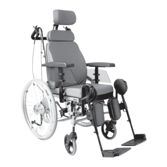
OVERVIEW The overview (fig.1 and 2) shows the important components and control devices of the wheelchair. 1 Push bar 2 Back cushion 3 Armrest 4 Seat cusion 5 Calf plate 6 Legrest 7 Footplate 8 Lever for height adjustment of the legrest 9 Steering wheel 10 Handrims... -
Page 11: Stowage/Transport
STOWAGE/TRANSPORT STOWING THE WHEELCHAIR The parking brakes are to be engaged before all assembly work. – This pre- vents the wheelchair from rolling away accidentally. For stowage of the wheelchair remove the armrests (fig. 3/ ), the legrests (fig. 3/ ) and the backrest (fig. -
Page 12: Assembly Of The Wheelchair
ASSEMBLY OF THE WHEEL- CHAIR To assemble the wheelchair mount all parts in reverse order. During reassembly, ensure that each part is correctly installed and securely fastened. Check that components are correctly positioned. Check the correct seating of the components. Note: The securing ring of the cotter pin has to be folded over completely... -
Page 13: Loading And Transportation
LOADING AND TRANSPOR- TRANSPORT IN HANDI- TATION CAPPED TRANSPORT AUTO- MOBILE Attention: For the loading and the transport Note: in vehicles, you must leave the For transport in vehicles we recom- wheelchair and sit in a suitable seat mend to leave the wheelchair and in the vehicle. -
Page 14: Product Liability Instructions
Safety instructions Note: The headrest on the wheelchair When transporting a person, make serves as a support for the posture sure that there are no objects of the head, not as a transport se- jammed underneath the straps! – curity. Therefore a handicapped Thus you avoid painful pressure transport vehicle-firm headrest is points. -
Page 15: Components
COMPONENTS ARMRESTS Attention: Do not use wheelchair without armrests guards fitted. Do not use the armrests to lift or carry the wheelchair. Adjusting the seat width The seat width can be adjusted by a lateral displacement of the armrests (fig. 7). Operate parking brakes. -
Page 16: Remove The Armrest
Remove the armrest Loosen the clamping screw (fig. 9/ and pull off the armrest upwards. Height adjustment of the arm- rest For height adjustment of the armrest loosen the clamping screw (fig. 9/ so far that no damage to the coating occurs during the adjustment. -
Page 17: Depth Adjustment Of The Armrest
Depth adjustment of the arm- rest The armrest can be adjusted in depth. For this screw out the two attachment screws (fig. 10/ ). After reposition- ing the armrest to position screw in and tighten the attachment screws (fig. 10/ Height adjustment of the clothes guard Loosen the clamping screws (fig. -
Page 18: Legrests
LEGRESTS Attention: Do not use the leg supports to lift or carry the wheelchair. • The legrests are not secured against removal. Note this when handling (e.g. transport). • The parking brakes are to be en- gaged before all assembly work. – This prevents the wheelchair from rolling away accidentally. -
Page 19: Swivelling Away The Side
Swivelling away the side The legrests are secured with a lock against unintentional swivelling. Slightly lift the legrest so that it can be swivelled outward over the lock. When the legrest is swivelled away by 90°, the 90° lock engages (fig. 13). For further swivelling slightly lift the legrest out of the lock. -
Page 20: Remove The Legrests
Remove the legrests By lifting the legrest it can be swiv- elled away or be removed toward the top (fig. 15). Note: Watch that the tube of the legrest does not jam in the guide rail. For this lift it slightly. -
Page 21: Attaching The Legrests
Attaching the legrests Hang the legrest from the top into the respective legrest receptacle and swivel forward until it locks into place. Attention: After swivelling the legrest inward again do not forget to check the corresponding locking device. Adjusting the entry width The legrest receptacle on the side frame can be adjusted sideways, through which the entry width can be... -
Page 22: Height-Adjustable Legrests
HEIGHT-ADJUSTABLE LEGRESTS Folding up the footplates For entry into, exiting the wheelchair or scuttling (forward motion of the wheelchair with the feet) the foot- plates (fig. 16.1/ ) are to be folded up first and the calf plates (fig. 16.1/ ) folded outward. -
Page 23: Height Adjustment Of The Legrest
Height adjustment of the legrest Sit in the wheelchair and ask a attend- ant to lift the legrest to the required level (fig. 17). The length adjustment is given through the turning point at the height of the knee joint. 1. -
Page 24: Height Adjustment Of The Footplates
Height adjustment of the foot- plates Tools, depending on model version: 1 x open-end or ring spanner WW* 13 or without tools Loosen the clamping screws (fig. 19/ ) so far that no damage to the coat- ing occurs during the adjustment. De- pending on the model version the footplate (fig. -
Page 25: Height Adjustment Of The Calf Plates
Height adjustment of the calf plates Tools: 1 x hexagonal stud wrench WW* 5 The calf plate can be adjusted in height after loosening the clamping screw (fig. 21/ Retighten the clamping screw (fig. 21/ ) after the adjustment. Depth adjustment of the calf plates The depth adjustment is effected by displacing the attachment screws (fig. -
Page 26: Back Cushion
BACK CUSHION The back cushion (fig. 24) can be re- moved for stowage/transport. Note: The cover can be removed with the zipper for washing. Remove the back cushion Operate parking brakes. – This pre- vents the wheelchair from rolling away accidentally. -
Page 27: Seat Cushion
SEAT CUSHION Note: The cover can be removed with the zipper for washing. To remove the cover the seat cushion can be disassembled together with the legrest frame. Remove the legrests, view chapter < legrests >. Loosen the clamping screw (fig. 27/ on each side so that no damage oc- curs to the coating during the adjust- ment. -
Page 28: Adjusting The Seat Depth
Adjusting the seat depth To adjust the seat depth, loosen the clamping screw (fig. 28/ ) on each side so far that no damage to the coat- ing occurs during the adjustment. Note: For the seat depth adjustment the backrest should be leaned slightly to the back so that the seat surface can be freely moved at the back cushion. -
Page 29: Seat Angle
SEAT ANGLE Adjustment of seat angle The seat unit is steplessly adjustable in angle through the gas spring form -8° to +26° (fig. 29). Attention: During the adjustment of the seat angle the push bar is to be held with both hands, because other- wise there is a danger of tilting. -
Page 30: Backrest With Angle Adjustment
BACKREST WITH ANGLE ADJUSTMENT Adjusting the angle of the backrest The backrest is steplessly adjustable through the gas spring adjustment form -10° to +35°. Attention: During the angle adjustment the push bar is to be held with both hands, because otherwise there is a danger of tilting. -
Page 31: Push Bar
PUSH BAR The push bar (fig. 32) is progressively adjustable in height. Height adjustment of the push The clamping screws (fig. 32.1/ ) are to be loosened for stepless height ad- justment. Loosen the clamping screws so far that no damage to the coating occurs during the adjustment. -
Page 32: Brakes
BRAKES The parking brakes are part of the most important safety elements of a wheel- chair. This function is provided by tog- gle joint brake/pressure brakes or air pressure independent drum brakes. Attention: Please observe the maintenance instructions as well as instructions in the section <... -
Page 33: Brake Lever For User
Brake lever for user With the brake levers for the driver (fig. 35) a metered braking of the driv- ing speed (operating brake) is possi- ble. By locking this brake the wheelchair is to be secured against unintentional rolling off (parking brake). Operating brake The braked of the wheelchair can be achieved over the handrims. -
Page 34: Parking Brake
Parking brake Press both brake levers forward as far as possible (fig. 35.1). The brakes en- gage and the wheelchair can no long- er be pushed (parking brake). Attention: For operational readiness the brake levers must be disengaged. • Do not leave wheelchairs with 35.1 puncture proof (PU) tyres over long- er periods of time with the knee-... -
Page 35: Adjusting The Parking Brake
Adjusting the parking brake The knee-lever brakes have to be re- adjusted after each change of the axle position, wheel size and tyres of the drive wheels. Loosen the clamping screws (fig. 37/ ) of one knee-lever brake. Preset the knee-lever brake. – Push the brake bolt of the deactivated knee-le- ver brake about 15 mm –... -
Page 36: Drum Brake For Attendant
Drum brake for attendant A metered braking from driving speed (operating brake) is possible with the brake levers of the drum brakes. By locking this brake the wheelchair is to be secured against unintentional rolling off (parking brake). Locking the drum brakes Pull both brake levers evenly to secure the wheelchair against unintentional rolling away. -
Page 37: Loosen The Drum Brakes
Loosen the drum brakes Pull both brake levers (fig. 41/ ) un- til the latches (fig. 41/ ) automati- cally jump out of the lock. Release both brake levers. – The park- ing brakes are release and the wheel- chair ready to go. Attention: For driving the front and rear brake levers must be disengaged. -
Page 38: Adjusting The Drum Brakes
Adjusting the drum brakes (Fig. 42) Tools: 1 x open-end spanner WW*10 Loosen the counter nut (fig. 43/ Then screw out the adjustment screw (fig. 43/ ) for tuning. Note: The wheelchair may not let itself be pushed with activated brake le- vers (second locking position, fig 39). -
Page 39: Drive Wheels
DRIVE WHEELS (For version with quick-release axle) These can be taken off or attached without tools for transporting the wheelchair, adjusting the drum brakes or exchanging the drive wheels. Remove the drive wheel without protection cap: Press the locking button in the center of the hub (fig. -
Page 40: Handrims
Handrims All handrims are designed for a 15 mm (fig. 46) and 25 mm (standard adjust- ment) distance to the drive wheel. Attention: Replacement of handrims or chang- ing the handrim distance is to be carried out by your specialist work- shop. -
Page 41: Wheel Base
Wheel base For a displacement of the gravitational centre the drive wheels can be mount- ed in a further position (fig. 47/ short wheelbase: – less strength required – more agile driving behaviour – increased danger of tilting large wheelbase: –... -
Page 42: Steering Wheels
STEERING WHEELS Wheel change The steering wheels (fig. 48) can be exchanged without any problems. Tools: 1 x hexagonal stud wrench WW* 5 Note: Before disassembly of the screwed connection watch for the position of the washer and distancer in or- der to reassemble them correctly! For removal of the wheels the screw axle (fig. -
Page 43: Seat Height
SEAT HEIGHT The drive wheel can be mounted in four further positions to adjust the seat height (fig. 49). The steering wheel can be mounted in two axle positions (fig. 50/ ). Ad- ditionally there are three further at- tachment positions (fig. 51) in the cas- tor bushing for the screwed connec- tion to the frame. -
Page 44: Support Castors
SUPPORT CASTORS The support castors (fig. 52) serve to raise the tilting stability and can be swivelled inward underneath the seat (fig. 53). Attention: In certain situation the support cas- tors do not provide sufficient pro- tection against falling over. Therefore, do not: Leaning far back with the upper body. -
Page 45: Height Adjustment
Height adjustment The support castors are height adjust- able. After loosening the clamping screws (fig. 54/ ) position the tube of the support castor (fig. 54/ ) in accord- ance with the drive wheel. Tighten the clamping screw (fig. 54/ Correct support castors length The support castors must reach further out than the drive wheels in order to... -
Page 46: Options
OPTIONS Options are not a part of the standard scope of supply. Note: – Options of external companies can cause interferences and may lead to a termination of the conformity of the product with EU-regulation 93/42/EWG. – Retrospective assembly may only be carried out by an specialist workshop! HEADREST... -
Page 47: Back Extension
Back extension Note: The cover can be removed with the zipper for washing. For height adjustment of the beck ex- tension (fig. 58/ ) the clamping screw (fig. 59/ ) is to be loosened so far that no damages occur to the coating during the adjustment. -
Page 48: Lap Belt
LAP BELT The lap belt is used for securing a per- son sitting in the wheelchair. – Additional stabilization of the sit- ting position. – Prevents the user from falling for- wards out of the wheelchair. – Continuous adjustment to suit the user’s needs. -
Page 49: Strapping On The Lap Belt With Lock
Strapping on the lap belt with lock Pull both belt halves to the front and slide the catch halves together so that they latch together (fig. 61). Then carry out a pull test. You open the lap seatbelt by pressing in the red unlocking button (fig. -
Page 50: Side Cushions
SIDE CUSHIONS The side cushions (fig. 62/ ) raise the seating stability and can be adjusted sideways in depth and height. Sideward adjustment Loosen the clamping screw (fig. 63/ ). Slide the side cushion into the desired position. Retighten the clamp- ing screw (fig. -
Page 51: Therapy Table
THERAPY TABLE Attention: Place, adjust and reposition or re- move the therapy table only after activating the brakes. • Sharp objects (e.g. watches, rings, knives or belt buckles) as well as coarse dust can cause unattractive brush marks in the surface of the therapy table. -
Page 52: Abduction Wedge
ABDUCTION WEDGE The abduction wedge bracket needed for this can also be assembled on an afterthought underneath the front seat surface. Depth adjustment Loosen the clamping screws (fig. 68/ ) so far that no damage to the coat- ing occurs during the adjustment. After loosening the clamping screw (fig. -
Page 53: Support Castors With Foot Caps
SUPPORT CASTORS WITH FOOT CAPS (Fig. 69) The foot cap is used by the attendant while overcoming an obstacle to slightly tilt the wheelchair. Note: Observe the chapter < support cas- tors > for swivelling and height adjustment of the support castor. -
Page 54: Walking Aid Holder
WALKING AID HOLDER The walking aid holder serves to hold crutches and walking sticks and can also retrospectively be assembled by a specialist workshop. Attention: Have a defective band (fig. 70/ or defective cup (fig. 71/ ) re- placed by a specialist workshop! •... -
Page 55: Maintenance
MAINTENANCE Washing instructions: If it is required to wash the upholstery CARE covers, please observe the following instructions: Seat- and back cushion: – Delicate cycle 40 °C. The upholstery covers can be removed with the zipper for washing. The syn- –... -
Page 56: Maintenance
MAINTENANCE Plastic parts: The plastic panels or similar consist of For safety reasons and in order to pre- high value plastics. vent accidents that result in wear not timely noticed have the wheelchair – Only clean the plastic parts with checked and maintained in annual in- warm water and neutral detergent tervals by a specialist dealer. -
Page 57: Maintenance Instructions
Maintenance instructions Every 8 weeks (depending on frequency of use) Before use: Check all moveable parts for func- Check the brake equipment for tion and practicability. flawless function. Provide the following parts with a Activate and lock the brake lever. few drops of oil: The braked wheels may no longer turn under operation conditions. -
Page 58: Repair
REPAIR Whenever a wheelchair change/mod- ification is carried out by the special- To conduct repair or maintenance ist dealer, the supplementary informa- work trustfully contact a specialist tion, e.g. assembly/operating instruc- workshop. Personnel there are well tions must be attached to the operat- trained to carry out the work required. -
Page 59: Technical Specifications
TECHNICAL SPECIFICATIONS All data within the following table relates to the standard version of the stated model. Dimension tolerance +/-1,5 cm, +/-2° Model: ................... SOLERO 9.072 Dimensions (unless otherwise noted with 24“ drive wheels) Length with legrests 774/76 and seat depth 42 cm: ..........118 cm without legrests 774/76 with seat depth 42 cm: ......... - Page 60 Height of back cushion Frame 1: ......................44 cm Frame 2: ......................54 cm Width of backrest Frame 1: ......................41 cm Frame 2: ......................48 cm Armrest height from seat, with cushion (stepless): ............ 19 to 26 cm Height of push bar on seat height 41 cm (stepless): ............
- Page 61 Permitted inclination/slopes permitted inclination: ..................8 % permitted slopes: .................... 8 % Stability against tipping over: ................ 8 % Weights permitted overall weight (with legrests 774)*: ......... 168 kg maximum user weight (including load): ............ 130 kg maximum additional load: ................10 kg Weight empty: ...................
-
Page 62: Guarantee
GUARANTEE Guaranty is not granted for surface damages, tyres of the wheels, damag- es due to loosened screws or nuts as For this product we accept the guar- well as worn out attachment holes anty according to the legal regula- due to frequent assembly work. -
Page 63: Guarantee Coupon
GUARANTEE COUPON Fill in the details! If necessary, copy and return. Guarantee Model designation: Delivery note no.: Fz-I-Nr. (view type plate): Date of delivery: Stamp of the specialist dealer:... - Page 64 ORTOPEDIA GmbH Salzredder 30 D-24149 Kiel • Postfach 64 09 D-24125 Kiel • Telephone: +49 (0)431 2003 - 0 Fax: +49 (0)431 2003 - 378 Internet: www.ortopedia.de e-mail: info@ortopedia.de QM system certified to DIN EN ISO 9001 and DIN We move people.
Need help?
Do you have a question about the solero 9.072 and is the answer not in the manual?
Questions and answers