Table of Contents
Advertisement
Advertisement
Table of Contents

Subscribe to Our Youtube Channel
Related Manuals for QDI Advance 10T Series


Summary of Contents for QDI Advance 10T Series
- Page 1 Item Checklist Notice...
-
Page 2: Declaration Of Conformity
Declaration of conformity QUANTUM DESIGNS(HK) LTD. 20th Floor, Devon House, Taikoo Place, 979 King’s Road, Quarry Bay, Hong Kong declares that the product Mainboard Advance 10T is in conformity with (reference to the specification under which conformity is declared in accordance with 89/336 EEC-EMC Directive) "... - Page 3 Declaration of conformity Trade Name: QDI Computer ( U. S . A. ) Inc. Model Name: Advance 10T Responsible Party: QDI Computer ( U. S. A.) Inc. Address: 41456 Christy Street Fremont, CA 94538 Telephone: (510) 668-4933 Facsimile: (510) 668-4966...
- Page 4 C O N T E N T S C O N T E N T S C O N T E N T S C O N T E N T S C O N T E N T S 1.
- Page 5 C O N T E N T S C O N T E N T S C O N T E N T S C O N T E N T S C O N T E N T S Jumper Settings..............
- Page 6 Note: This manual is suitable for mainboards of Advance 10T series. Each mainboard is carefully designed for the PC user who wants diverse features. A10T: without onboard Audio A10T-A: with onboard Audio Caution 1. Be sure to add some Silicone Grease between the CPU and the heatsink of FAN to keep them fully contact , meanwhile to meet the heat sink requirement.
-
Page 7: Chapter 1 Introduction
Chapter 1 Introduction Overview Key Features Form Factor # " Microprocessor ® ® ® ® Chipset... - Page 8 Memory # " " " #" Onboard IDE #" " " " " " # # # # # " " " " " # # # # # Onboard I/O " " " " " ’’ ’’ # # # # # "...
- Page 9 " " " " " # # # # # # # # # # # # # # # BIOS # " # " # " # " # " #" #" #" #" #" # " # " # "...
-
Page 11: Installation Instructions
Chapter 2 Installation Instructions External Connectors PS/2 Keyboard Connector, PS/2 Mouse Connector USB1 ,USB2 Connectors USB1 USB2 Be sure to unplug the AC power supply before adding or removing expansion cards or other system peripherals, otherwise your motherboard and expan- sion cards might be seriously damaged. - Page 12 USB3,4 Connectors C U T C U T Parallel Port, Serial Port Connectors (UART1, UART2) Line-in Jack, Microphone-in Jack, Speaker-out Jack and MIDI/ Joystick Connector(available on A10T-A)
-
Page 13: Atx Power Supply Connector & Power Switch( Power Sw)
ATX Power Supply Connector & Power Switch( POWER SW) Push once 5VSB PW-OK PS-ON 3.3V -12V 3.3V 3.3V Note: * If you change “soft-off by PWRBTN” from default “Instant-off” to “Delay 4 Sec” in the “POWER MANAGEMENT SETUP” section of the BIOS, the power button should be pressed for more than 4 seconds before the system powers down. - Page 14 Power LED Connector (PWRLED) GREEN LED Connector (GREENLED) ACPI LED Connector (ACPILED) Hardware Green Connector (SLEEP SW) Key Lock Connector (KEYLK)(Reserved) SPEAKER RESET GREEN LED KEYLK SLEEP POWER LED POWER ACPI LED SPEAKER GREEN LEDKEYLK RESET ACPI POWER POWER SLEEP...
- Page 15 Wake-Up On LAN ( WOL ) +5V SB Signal for waking up Wake-Up On Internal Modem ( WOM ) +5V Standby Signal for waking up...
- Page 16 Internal Audio Connectors ( CD_IN, MODEM,AUXIN) (available on Advance 10T-A) AUXIN Right AudioChannel LeftAudio Channel MODEM Phone-In (from Modem) Mono-Out (to Modem) CD_IN Left Channel Right Channel Common Fan Connectors (BAKFAN,CPUFAN, CHSFAN) FAN GND +12V BAKFAN FAN GND +12V CPUFAN SENSE SENSE FAN GND...
- Page 17 Infrared Header (IrDA) C U T IRRX IRTX Audio/Modem Riser Slot (AMR) & AMR Sound Option(JSD) (Jumper JSD is available on Advance 10T-A) Note: The Advance 10T mainboard supports Primary AMR card only.
- Page 18 Audio Interface(Reserved) Symbol Symbol Active LINE Out(R) Active LINE Out(L) Microphone in GND (ALO) GND (ALO) GND(+12) GND(+12) Line in Speaker +12V(1A) (Cut away ) (Active Audio) Speaker Out GND ( MIC ) Front LINE Out( R ) LINE Next( R ) Front LINE Out( L ) LINE Next( L ) GND (FLO)
- Page 19 Chassis Security Switch (CHSSEC) Indicate signal VCC3 Main Expansion Slots and Connectors...
-
Page 20: Jumper Settings
Jumper Settings → Overclocking Jumper Setting (JCLK1, JCLK2) Warning: Be sure your selection is right. CPU over speed will be dangerous! We will not be responsible for any damages caused. - Page 21 FSB Frequency Selection(JFSB1, JFSB2) Enable USB Device Wake-up Function (JUSB1, JUSB2) JUSB2 1 2 3 JUSB1...
- Page 22 CPU Bus Ratio Selection (JX1, JX2,JX3, JX4)(optional) then CPU RATIO X4.5 close open open close open close close open open X5.5 close open open open open close close close close X6.5 open open close close open close close open X7.5 open open close...
- Page 23 Clear CMOS (JCC) CPU Core Voltage Setting (JV1, JV2, JV3, JV4,JVT1)(optional) JVT1...
- Page 24 JVT1 CORE Warning: To set CPU core voltage higher than its default core voltage is not suggested. If you do, we will not be responsible for any damages caused.
- Page 25 BIOS Protection Function Jumper ( JAV )
- Page 26 Enable/Disable Onboard Audio Setting ( JSD ) (available on A10T-A)
-
Page 27: Chapter 3 Bios Description
Chapter 3 BIOS Description Utility Support: AWDFLASH.EXE We strongly recommend you only upgrade BIOS when encounter problems. Before upgrading your BIOS, review the description below to avoid making mistakes, destroying the BIOS and resulting in a non-working system. Follow the instruction through the process. Don’t turn off power or reset the system until the BIOS upgrade has been completed. -
Page 28: Entering Setup
AWARD(Phoenix) BIOS Description Entering Setup Press <Del> to enter SETUP Load Fail-Safe Defaults Load Optimized Defaults Standard CMOS Features Setup... - Page 29 Hard Disk Primary Master/Primary Slave/Secondary Master/Secondary Slave...
- Page 30 CHS mode LBA (Logical Block Addressing) mode LARGE mode Remark...
- Page 31 Video Halt On Memory...
-
Page 32: Speedeasy Cpu Setup
SpeedEasy CPU Setup Item Option Description Enabled " Disabled #" Enabled Disabled #" Default Warning:... -
Page 33: Advanced Bios Features Setup
Advanced BIOS Features Setup The following indicates the options for each item and describes their meaning. Item Option Description #" Enabled Disabled #" Enabled Disabled #" Enabled Disabled #" Enabled Disabled #" Enabled Disabled #" ® Enabled ® Disabled... - Page 34 Item Option Description #" Enabled Disabled #" Disabled Floppy #" Enabled Disabled #" #" Normal Fast #" System Setup #" Non-OS2 #" Enabled Disabled #" Enabled Disabled #" Enabled Disabled...
- Page 35 Item Option Description #" Enabled " Disabled #" Enabled Note: Enabling this item can protect the system BIOS from being attacked by severe virus such as CIH. Therefore disable this item only when wanting to flash BIOS, afterwards set this item as Enabled (default). Disabled...
-
Page 36: Advanced Chipset Features Setup
Advanced Chipset Features Setup The following indicates the options for each item and describes their meaning. Item Option Description #" Normal Medium Fast Turbo SDRAM 8/10ns #" #" Host Clk Hclk-33M #" 15M-16M Disabled #" Enabled Disabled #" Enabled Disabled... - Page 37 Item Option Description #" Enabled Disabled #" 4M~128M #" Enabled Disabled Auto manual Enabled Disabled Enabled Disabled #" Enabled Disabled Auto Disabled #" Auto Disabled #" Enabled Disabled #" Enabled Disabled #" Enabled Disabled...
- Page 38 Item Option Description Enabled " Disabled Enabled " Disabled Enabled " Disabled Enabled " Disabled " Disabled...
-
Page 39: Power Management Setup
Power Management Setup The following indicates the options for each item and describes their meaning. Item Option Description Enabled " Disabled press Enter " User Define " Min Saving Max Saving " Disabled 1 - 15 Min " Disabled 1Min~ 1Hr "... - Page 40 Item Option Description S1(POS) " S3(STR) " Always On " Suspend off Blank Screen " V / H SYNC + Blank DPMS support " 3, 4, 5, 7, 9 10, 11 Instant _off #" Delay 4 Sec """""""""""" #" Auto """"""""""""""...
- Page 41 Item Option Description "" #" NONE #" LPT/COM # " #" Disable #" Enable #" Enabled Disabled Enabled " Disabled " Press Enter " Enabled " Disabled...
-
Page 42: Pnp/Pci Configuration Setup
PNP/PCI Configuration Setup Item Option Description " Enabled Disabled Manual " Auto (ESCD) Enabled " Disabled Enabled " Disabled Enabled " Disabled... -
Page 43: Integrated Peripherals
Integrated Peripherals Item Option Description Enabled Disabled Enabled Disabled Mode 0 - 4 Auto Auto Disabled PCI SLOT Enabled... - Page 44 Item Option Description Enabled Disabled 3F8/IRQ4, 2F8/IRQ3, 3E8/IRQ4, 2E8/IRQ3, Auto Disabled Standard " HPSIR ASK IR 378/IRQ7, #" 278/IRQ5, 3BC/IRQ7 Disabled #" Normal ECP, ECP/EPP # " EPP1.9 # " EPP1.7 Enabled #" Disabled Enabled #" Disabled 220H/240H #" 260H/280H...
- Page 45 Item Option Description #" IRQ5,7,9,10 DMA0~DMA3 #" Enabled # " Disabled # " 300/303H ..330-333H Enabled #" Disabled...
-
Page 46: Pc Health Status
PC Health Status Item Current Description Data Shown C/102 C/ 86 3999RPM 3998RPM 1.5V #" 2.49 3.32V 4.83V 11.79V... -
Page 47: Supervisor / User Password
Supervisor/ User Password ENTER PASSWORD PASSWORD DISABLED System Setup Boot with BIOS defaults... - Page 48 Appendix QDI Driver CD 2000 Install Driver Accessory Browse CD Utility Documents...
- Page 49 LogoEasy CBLOGO.EXE * We reserve the right of modifying the default full-logo of QDI without further notification.
- Page 50 RecoveryEasy Introduction: Operation Process: Partition Interface (see figure-1) 1.0 Install RecoveryEasy for the first time...
- Page 51 1.1 CREATE PAR Function : Limitation : Steps Note:...
- Page 52 1.2 DELETE PAR Function : Limitation : Steps 1.3 ACTIVE PAR Function : Limitation : Steps Note 1.4 CREATE MIR Function : Limitation : Steps 1.5 DELETE MIR Function : Limitation : Steps 1.6 UNINST SFW Function : Limitation : Steps Note...
- Page 53 1.7 OTHERS F12 : ESC : Recovery Interface (see figure-3) 2.1 BACKUP PAR Function : Limitation : Steps:...
- Page 54 2.2 RE-CVR PAR Function : Limitation : Steps: Note: 2.3 ATTRIB PAR Function : Limitation : Steps Note:...
- Page 55 2.4 BACKUP CMS Function : Limitation : Steps 2.5 RE-CVR CMS Function : Limitation : Steps Note 2.6 CHANGE PWD Function : Limitation : Steps Note: 2.7 Others Ctrl+Bksp :...
- Page 56 FAQ: What does RecoveryEasy do? Does RecoveryEasy occupy the system resources? RecoveryEasy utilizes Build-in BIOS skill, what is build-in BIOS? Are there any hard disk limitations of RecoveryEasy? Are there any OS limitations of RecoveryEasy? Why does the system halt when HDD access mode is changed (eg. LBA- >LARGE)?
- Page 57 Why does the remainder size plus partitions size not match the total size shown in RecoveryEasy sometimes? Are there any other disk partition tools that can modify the partition table made by RecoveryEasy? Why does it happen that a prompt “installation can not continue” pops up when installing Windows98 or a yellow exclamation mark shown beside IDE device in system properties? Why does the converting of FAT16->FAT32 in PQ Magic go wrong?
- Page 58 What if computer accidentally power off when backuping (recovering)? What if users lose the password? I t ’s very important for users to remember the password. Does RecoveryEasy protect hard disk against CIH?
- Page 59 BIOS_ProtectEasy Norton AntiVirus...
- Page 60 ManageEasy...
- Page 61 SpeedEasy Quick Setup P r o c e d u r e s :...
- Page 62 CPU SpeedEasy Setup Menu Warning:...
- Page 63 QDI BootEasy Note: Setting the jumper JAV as open if you encounter the above conditions.
- Page 64 QDI BootEasy...
- Page 65 QDI BootEasy BootEasy Setup Menu...
- Page 66 QDI BootEasy Nota:...
-
Page 67: Installation
QDI StepEasy(optional) 10MHz increase 10MHz decrease 1MHz increase 1MHz decrease button to run at the button to run at the default frequency select frequency Installation Instructions... - Page 68 To avoid accident, we recommend you to close your other program before run StepEasy. Note:...
- Page 69 Installation de la carte mère Advance 10T : Installation du système.
- Page 71 ATTENTION : lisez attentivement le manuel du RecoveryEasy traduit sur le CD- ROM QDI avant d’installer cette fonction. Très important : n’oubliez pas votre mot de passe, faute de quoi vous n’auriez plus accès au RecoveryEasy, même après avoir effectué un Clear CMOS.
- Page 72 Note: si vous ne déterminez pas la vitesse de votre unité centrale, votre système fonctionnera par défaut CMOS Setup Utility – Copyright© 1984-1999 Award Software SpeedEasy CPU Setup ATTENTION: Ne pas sélectionner une fréquence de fonctionnement du CPU supérieure à celle indiquée par le constructeur. Nous déclinons toute responsabilité...
- Page 73 Advance 12 Form Factor: Chipset: FSB: Memory: IDE: AGP: I/O: Optional: QDI Innovations: Advance 10BM Form Factor: Chipset: FSB: Memory: IDE: AGP: I/O: Audio: QDI Innovations: Welcome to visit www.qdigrp.com for details...
-
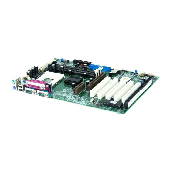
Page 74: Mainboard Layout
Mainboard Layout Mainboard Layout This layout is just for your reference...
Need help?
Do you have a question about the Advance 10T Series and is the answer not in the manual?
Questions and answers