Table of Contents
Advertisement
Quick Links
Chapter 1
Chapter 1
Introduction
K7VM400M Pro series of mainboards utilize VIA KM266 PRO+VIA 8235 or
8237 chipset, providing a fully compatible, high performance and cost-
effective mATX platform. The new integrated technologies, together with
TM
AC' 97 audio(2/6-channel), Integrated Unichrome
Graphics, AGP 4X, 6 /
8(with 8237 only) USB 2.0, 2 SATA(with 8237 only), and ATA133/100/66/
33, give customers an advanced, multimedia solution at reasonable price.
It provides 200/266/333MHz host bus speed to support AMD Athlon/Athlon
XP/Duron socket A processors and the DDR200/266/333 memory. It also
provides advanced features such as Wake up by USB devices function.
Suspending to RAM, the optimal implementation of the Advanced Configu-
ration and Power Interface (ACPI) specification, makes the PC' s power
consumption drop to the lowest possible level and enable quick wakeup.
K7VM400M Pro
1
Advertisement
Table of Contents

Related Manuals for QDI K7VM400M Pro Series


Summary of Contents for QDI K7VM400M Pro Series
- Page 1 Chapter 1 Chapter 1 Introduction K7VM400M Pro series of mainboards utilize VIA KM266 PRO+VIA 8235 or 8237 chipset, providing a fully compatible, high performance and cost- effective mATX platform. The new integrated technologies, together with AC’ 97 audio(2/6-channel), Integrated Unichrome Graphics, AGP 4X, 6 / 8(with 8237 only) USB 2.0, 2 SATA(with 8237 only), and ATA133/100/66/...
- Page 2 Introduction Form factor mATX form factor of 244mm x 200mm Microprocessor Supports AMD Athlon/Athlon XP/Duron socket A processors of 200/266/333MHz host bus speed Supports 200/266/333MHz host bus speed System memory Supports DDR200/266/333 SDRAM Supports 64/128/256/512Mb technology up to 2GB Provides two 184-pin DDR SDRAM interfaces Onboard IDE Supports Independent timing of up to 4 drives Supports Ultra ATA 33/66/100/133, PIO mode...
-
Page 3: Advanced Features
Chapter 1 Advanced features PCI 2.2 Specification Compliant Provides Trend ChipAwayVirus On Guard Supports Windows 98/2000/ME/XP soft-off Supports Keyboard Password Power-on function(optional) Onboard SATA(with 8237 only) Two SATA devices including SATA HDD and CDROM/DVD ROM devices Supports 150Mbps transfer rate. BIOS Licensed advanced AWARD(Phoenix) BIOS, supports flash ROM, plug and play ready Supports IDE CDROM/USB boot up. - Page 4 Installation Instructions Chapter 2 Installation Instructions This section covers External Connectors and Jumper Settings. Refer to the mainboard layout chart for locations of all jumpers, external connectors, slots and I/O ports. Furthermore, this section lists all necessary connector pin assignments for your reference. The par- ticular state of the jumpers, connectors and ports are illustrated in the following figures.
-
Page 5: External Connectors
Chapter 2 External Connectors PS/2 Keyboard/Mouse Connector PS/2 keyboard connector is for the usage of PS/2 keyboard. If using a standard AT size keyboard, an adapter should be used to fit this connector. PS/2 mouse connector is for the usage of PS/2 mouse. PS/2 Mouse connector PS/2 Keyboard connector USB1, USB2;... -
Page 6: Installation Instructions
Installation Instructions Line-in jack, Microphone-in jack and Speaker-out jack The Line-in jack can be connected to devices such as a cassette or minidisc player to playback or record. The Microphone-in jack can be connected to a microphone for voice input. The Speaker-out jack allows you to connect speakers or headphones for audio output from the internal amplifier. -
Page 7: Atx Power Supply Connector & Power Switch (Power Sw)
Chapter 2 ATX Power Supply Connector & Power Switch (POWER SW) The power switch (POWER SW) should be connected to a momentary switch. When powering up your system, first turn on the mechanical switch of the power supply (if one is provided), then push once the power switch. - Page 8 Installation Instructions Power LED Connector (PWR_LED) When the system is in S0 status, the LED is on. When the system is in S1 status, the LED is blink; When the system is in S3,S4, S5 status, the LED is off. The connector has an orientation.
-
Page 9: Infrared Header (Irda)
Chapter 2 USB5,6; USB7,8(with 8237 only) Besides USB1,2,3,4 on the back panel, K7VM400M Pro series of mainboards also have 10- pin headers on board which may connect to front panel USB cable( optional ) to provide additional four USB ports. - Page 10 Installation Instructions Audio Connectors (CD_IN, AUX_IN(optional)) CD_IN is Sony standard CD audio connector, it can be connected to a CD-ROM drive through a CD audio cable. AUX_IN allow you to receive stereo audio input from sound sources such as a TV tuner, or MPEG card. CD Right Channel CD_IN CD Left Channel...
- Page 11 Chapter 2 Wake-Up On Internal Modem (WOM)(optional) Through this function, the system which is in the suspend or soft-off status can be waked up by a ring signal received from the internal modem. When this function is used, be sure an internal modem card which supports this function is used. Then connect this header to the relevant connector on the modem card, set “...
- Page 12 Installation Instructions SPDIF OUT Connector(optional) The SPDIF output allow your digital audio input from digital audio devices. Cut away SPDIF out SPDIF JSPEAK Connector(optional) SPK_DATA SPK_VCC K7VM400M Pro...
-
Page 13: Jumper Settings
Chapter 2 Jumper Settings Jumpers are located on the mainboard, the clear CMOS jumper JCC, enable keyboard password power-on function jumper JKB etc. Pin 1 for all jumpers are located on the side with a thick white line (Pin1→ ), referring to the mainboard’ s silkscreen. Jumpers with three pins will be shown as to represent pin1 &... - Page 14 For bus ratio unlocked processor, this overclocking feature can be implemented by setting FSB as 200/266/333MHz, meanwhile adjusting the bus ratio (multiplier) in “ QDI Innovation features” in AWARD BIOS CMOS Setup and memorry. Warning: Be sure your selection is right. CPU over speeding is dangerous! We will not be responsible for any damages caused.
- Page 15 Enabled Setting the jumper BIOS_WP as open(default), meanwhile disabling the “ Flash Write Pro- tect” item from “ QDI Innovation features ” in AWARD BIOS CMOS Setup, allows you to flash the BIOS to the Flash ROM. Under special conditions, the jumper “ BIOS_WP” should be set as OPEN.
- Page 16 Installation Instructions Enable keyboard password power-on function (JKB)(optional) The mainboard provides the advanced keyboard password power-on function. Before using this function, set JKB with pin1 & pin2 closed. Otherwise, set JKB with pin2 & pin3 closed for disabling. Disable 1 2 3 Enable 1 2 3 Furthermore in order to implement this function, set “...
-
Page 17: Bios Description
Chapter 3 Chapter 3 BIOS Description The mainboard uses AWARD BIOS Setup program that provides a Setup utility for users to modify the basic system configuration. The information is stored in CMOS RAM so it retains the Setup information when the power is turned off. This chapter provides you with the overview of the BIOS Setup. - Page 18 1. Create a bootable system floppy diskette by typing Format A:/s from the DOS prompt under DOS6.xx or Windows 9x environment. 2. Copy AWDFLASH.EXE(version>=8 .24) from the directory \Utility located on QDI Driver CD to your new bootable diskette. 3. Download the updated BIOS file from the Website (http://www.qdigrp.com). Please be sure to download the suitable BIOS file for your mainboard.
- Page 19 <PgUp> or <PgDn> keys to select the value desired in each item. QDI Innovation Features This section describes QDI innovation EASY technology. Advanced BIOS Features This section allows you to configure your system for basic operation. You have the opportunity to select the system’...
- Page 20 BIOS Description Integrated Peripherals The integrated peripherals setup allows user to configure the onboard IDE controller, floppy disk controller, the printer port and the serial ports etc.. PC Health Status The PC health status display CPU and case fan speed. Load Fail-Safe Defaults The BIOS defaults have been set by the manufacturer and represent settings which provide the minimum requirements for your system to operate.
- Page 21 Appendix Appendix QDI Utility CD A QDI Utility CD is supplied with this mainboard, the contents contained in it are showed as below: 1. Driver Install Using this choice, you can install all the drivers for your mainboard . You should install the drivers in order, and you need to restart your computer until all the drivers are installed.
- Page 22 SpeedEasy BIOS provides you with a set of basic values for your processor selection instead of the jumper settings. The processor speed can be manually selected on the “ QDI Innovation features” menu screen. BootEasy BootEasy technology enormously improves the long BOOT process time of computers.
- Page 23 Appendix QDI BootEasy(German) BootEasy ist eine Neuentwicklung von QDI, die neue Innovation der QDI Easy- Technologien. Mit der BootEasy- Technologie Technik wird der Bootvorgang nur noch vier bis fü nf Sekunden in Anspruch nehmen, bis das Betriebssystem geladen wird. Der Grund fü r die lange Warterei liegt in den Routine-Abfragen, die das BIOS bei jedem Start abarbeitet.
- Page 24 Inserte el procesador en el socket y conecte el ventilador del procesador en el conector de su placa base QDI K7VM400M Pro marcado como “ CPUFAN” . Inserte los mó dulos de memoria en los bancos de memoria DIMM de su placa base QDI K7VM400M Pro.
-
Page 25: Instalación Del Sistema
Para má s informació n las funciones de la Bios, consulte el apartado “ BIOS Description” en el manual de usuario de la placa base QDI K7VM400M Pro). Presione la tecla « F10 » y seleccione la opció n “ Save & Exit Setup” en el menú de configuració n de la Bios para guardar los cambios y reiniciar el sistema. - Page 26 K7VM400M Pro (French): Inté gration du systè me : Vé rifier la pré sence de chaque é lé ment dans la boite de la carte mè re de la sé rie QDI K7VM400M Pro : Une carte mè re de la sé rie QDI K7VM400M Pro.
-
Page 27: Installation Du Système
Connecter les câ bles de l’ unité centrale de l’ ordinateur sur les broches inté gré es à la carte mè re de la sé rie QDI K7VM400M Pro et pré vues à cet effet. Dans ce but il est important de se ré... - Page 28 1. Driver Install : Avec cette option, il est possible d’ installer les pilotes de la carte mè re de la sé rie QDI K7VM400M Pro aisé ment. Il est important d’ installer les pilotes en respectant l’ ordre pré dé finit et de redé...
- Page 29 Appendix QDI K7VM400M Pro installazione mainboard (Italian): 1. Assicurarsi che la scatola sia completa: QDI K7VM400M Promainboard, cavo IDE e Floppy, jumpers, manuale dell’ utente della mainboard QDI K7VM400M Pro e cd-rom drivers. 2. Controllare che il cavo alimentazione proveniente dal computer-case sia sconnesso assicurarsi inolre di aver indossato corretamente il bracciale da polso collegato a massa.
- Page 30 Appendix Dopo questo ultimo passo procedere all’ installazione dei driver delle varie periferiche IL CD CONTENENTE I DRIVER DELLA VOSTRA MAINBOARD QDI E’ CONTENUTO NELLA SCATOLA Installazione driver E possibile installare tutti i driver della Vs. mainboard in modo facile e veloce.
-
Page 31: Installing The Audio Driver
Appendix Using 4-/6-Channel Audio(4-/6- Channel Audio Interface) The motherboard is equipped with Realtek ALC655 chip, which provides support for 6- channel audio output, including 2 Front, 2 Rear, 1 Center and 1 Subwoofer channel. ALC655allows the board to attach 4 or 6 speakers for better surround sound effect. The section will tell you how to install and use 4/6-channel audio function on the board. -
Page 32: Digital Audio Output
Appendix 6-Channel Analog Audio Output Line Out(Rear Channels) Line Out (Front channels) Line Out(Center & Subwoofer Channels) Description: Both Line In and MIC are converted to Line Out function under 6- channel configuration. Digital Audio Output Coaxial SPDIF jack Description: Connnet the SPDIF speakers to the Coaxial SPDIF jack. -
Page 33: Selecting 4- Or 6-Channel Setting
Appendix Selecting 4- or 6-Channel Setting 1. Click the audio icon from the window tray at the bottom of the screen. 2. Select any surround sound effect you prefer from the “ Environment” pull-down menu under the Sound Effect tab. Click here and the pull- down menu will appear 3. -
Page 34: Testing The Connected Speakers
Appendix 4. The following window appears. Headphone Output 2 Channels Output 4 Channels Output Keep UnSelect 6 Channels Output Status 5. Select the multi-channel operation you prefer from No. of Speakers. 6. Click OK Testing the Connected Speakers To ensure 4- or 6-channel audio operation works properly, you may need to test each connected speaker to make sure every speaker work properly. -
Page 35: Playing Karaok
Appendix Playing KaraOK The KaraOK function will automatically remove human voice (lyrics) and leave me-lody for you to sing the song. The function is applied only for 2-channel audio opera- tion, so make sure channel mode is selected in the “ No. of Speakers” column before playing KaraOK. -
Page 36: Cpu Installation Procedures
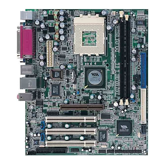
Appendix CPU Installation Procedures 1. Pull the lever sideways away from the socket. Then, raise the lever up to a 90-degree angle. 2. Look for the cut edge. The cut edge should point towards the lever pivot. The CPU will only fit in the correct orientation. - Page 37 Board Layout of K7VM400M Pro Note: The layout includes all options. It is for your reference only.
- Page 38 Top :Line in Top :PS/2 Mouse Middle:Speaker out Bttm:PS/2 Keyboard Bttm:Mic. in BIOS_WP USB1_2 Top :LAN(option) Bttm:USB3,4 JUSB1 ATX_ POWER North Bridge JUSB2 Socket 462 South Bridge DIMM1 DIMM2 IDE2 IDE1 SATA1 SATA2 Note: pin1 for a jumpers are located on the side with black line. 1.
Need help?
Do you have a question about the K7VM400M Pro Series and is the answer not in the manual?
Questions and answers