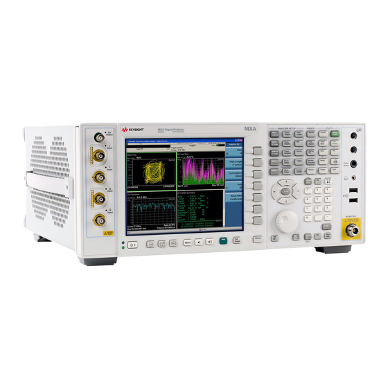
Keysight Technologies N9020A MXA Instruction
Signal analyzer
Hide thumbs
Also See for N9020A MXA:
- Installation note (9 pages) ,
- Getting started manual (119 pages) ,
- Measurement manual (83 pages)
Table of Contents
Advertisement
Quick Links
Advertisement
Table of Contents

Related Manuals for Keysight Technologies N9020A MXA


Summary of Contents for Keysight Technologies N9020A MXA
- Page 1 Keysight N9020A MXA Signal Analyzer Functional Tests...
-
Page 2: Safety Notices
DOCUMENT THAT CONFLICT WITH THESE TERMS, THE WARRANTY beyond those set forth in the TERMS IN THE SEPARATE EULA shall apply, except to the © Keysight Technologies, Inc. AGREEMENT WILL CONTROL. extent that those terms, rights, or 2006-2016 licenses are explicitly required... - Page 3 Where to Find the Latest Information Documentation is updated periodically. For the latest information about these products, including instrument software upgrades, application information, and product information, browse to one of the following URLs, according to the name of your product: http://www.keysight.com/find/mxa To receive the latest updates by email, subscribe to Keysight Email Updates at the following URL: http://www.keysight.com/find/MyKeysight...
-
Page 4: Table Of Contents
Table of Contents 1. Functional Tests Functional Test Versus Performance Verification ........... . 8 Contents of this Document. -
Page 5: Functional Tests
Keysight N9020A MXA Signal Analyzer Functional Tests Guide Functional Tests Functional tests are tests of various instrument parameters that give a high degree of confidence that the analyzer is operating correctly. They are recommended as a check of analyzer operation for incoming inspection or after a repair. -
Page 6: Functional Test Versus Performance Verification
Functional Tests Functional Test Versus Performance Verification Functional Test Versus Performance Verification Functional tests use a minimum set of test equipment to check a much smaller range of parameters (and a limited number of data points for each parameter) than do performance verification tests. Functional tests use limits that are wider than the published specifications;... -
Page 7: Contents Of This Document
Functional Tests Contents of this Document Contents of this Document This chapter includes the following: — “Before Performing a Functional Test” on page 10 (what to do first). — “Test Equipment” on page 11 (a list of the equipment required for all of the tests). -
Page 8: Before Performing A Functional Test
Functional Tests Before Performing a Functional Test Before Performing a Functional Test 1. Ensure that you have the proper test equipment. 2. Switch on the unit under test (UUT) and let it warm up (in accordance with warm-up requirements in the instrument specifications). 3. -
Page 9: Test Equipment
Functional Tests Test Equipment Test Equipment The table below summarizes the test equipment needed to perform all of the functional tests. Alternate equipment model numbers are given in case the recommended equipment is not available. If neither the recommended nor the alternative test equipment are available, substitute equipment that meets or exceeds the critical specifications listed. - Page 10 Functional Tests Test Equipment Table 1-1 Analyzer Al ternate Recommended Option Item Critical Specifications Keysight Keysight Model Model Signal Source Synthesized Sweeper Frequency: 10 MHz to 26.5 GHz 83630B, Harmonic level: < − 40 dBc 83640B, Amplitude range: 10 to − 20 dBm 83650B Frequency Accuracy: 0.02% Power Meter...
-
Page 11: Displayed Average Noise Level (Danl)
Keysight N9020A MXA Signal Analyzer Functional Tests Guide Displayed Average Noise Level (DANL) Test Limits (with 0 dB input attenuation) Table 2-1 for values. The Displayed Average Noise Level (DANL) of the signal analyzer is measured across a 10 kHz frequency span at several center frequencies. The analyzer input is terminated into a 50Ω... -
Page 12: Procedure
Displayed Average Noise Level (DANL) Procedure Procedure 1. Configure the equipment as shown in Figure 2-1 2. Press Mode, Spectrum Analyzer, Mode Preset on the analyzer. 3. Set up the signal analyzer by pressing: FREQ Channel, Center Freq, 10, MHz Input/Output, RF Input, RF Coupling, select DC SPAN X Scale, Span, 10, kHz AMPTD Y Scale, –70, dBm... - Page 13 Displayed Average Noise Level (DANL) Procedure 12.Change the analyzer center frequency to the next value listed in Table 2-1. Press: FREQ Channel, Center Freq, [Table 2-1 Value], GHz 13.Repeat step 4 through step 12 to fill in the remainder of Table 2-1 for your analyzer frequency range.
-
Page 14: Frequency Readout Accuracy
Keysight N9020A MXA Signal Analyzer Functional Tests Guide Frequency Readout Accuracy Test Limits Frequency Readout Accuracy is equivalent to the following equation: ±(0.25% × span + 5% × RBW + 2 Hz + 0.5 × horizontal resolution) See results table for actual values. - Page 15 Frequency Readout Accuracy Figure 3-1 Frequency Readout Accuracy Test Setup...
-
Page 16: Procedure
Frequency Readout Accuracy Procedure Procedure 1. Configure the equipment as shown in Figure 3-1. Confirm the analyzer’s built-in auto alignment has been performed within the past 24 hours. 2. On the synthesized sweeper, press PRESET, then set the controls as follows: FREQUENCY, 1505, MHz POWER LEVEL, –10, dBm... -
Page 17: Second Harmonic Distortion (Shd)
Keysight N9020A MXA Signal Analyzer Functional Tests Guide Second Harmonic Distortion (SHD) Test Limits Applied Frequency Mixer Level Distortion 40 MHz –10 dBm < –55 dBc This test checks the second harmonic distortion of the signal analyzer by tuning to twice the input frequency and examining the level of the distortion product. - Page 18 Second Harmonic Distortion (SHD) Critical Specifications Recommended Item (for this test) Keysight Model Filter, 50 MHz Low Pass Cutoff Frequency: 50 MHz 0955-0306 Rejection at 65 MHz: > 40 dB Rejection at 75 MHz: > 60 dB Synthesized Sweeper Frequency: 50 MHz Spectral Purity: Better than –30 dBc Figure 4-1 Second Harmonic Distortion Test Setup...
-
Page 19: Procedure
Second Harmonic Distortion (SHD) Procedure Procedure 1. Configure the equipment as shown in Figure 4-1. 2. Press Mode, Spectrum Analyzer, Mode Preset on the signal analyzer and Preset the synthesized sweeper. 3. Set up the synthesized sweeper by pressing: Frequency, 40, MHz Amplitude, –10, dBm 4. -
Page 20: Amplitude Accuracy At 50 Mhz
Keysight N9020A MXA Signal Analyzer Functional Tests Guide Amplitude Accuracy at 50 MHz Test Limits Amplitude Accuracy should remain within 1.13 dB of the measured source value across the range of source levels and changes in resolution bandwidth. The Preamp (option P03, P08, P13, P26) should remain within ±1.3 dB of measured values. - Page 21 Amplitude Accuracy at 50 MHz Figure 5-1 Amplitude Accuracy Test Setup...
-
Page 22: Procedure
Amplitude Accuracy at 50 MHz Procedure Procedure 1. Zero and calibrate the power meter. 2. Configure equipment as shown in Figure 5-1, with the power splitter connected directly to the signal analyzer input through the step attenuator and adapter. To minimize stress on the test equipment connections, support the power sensor. - Page 23 Amplitude Accuracy at 50 MHz Procedure h. Record the signal amplitude, as measured by the analyzer in the Measured Amplitude column of Table 5-1 i. Calculate the signal amplitude accuracy error using the following equation, and record the results under the Amplitude Accuracy Error column: Amplitude Accuracy Error = Meas_amp + Step Attenuator −...
-
Page 24: Testing Preamp Option (P03, P08, P13, P26)
Amplitude Accuracy at 50 MHz Testing Preamp Option (P03, P08, P13, P26) Testing Preamp Option (P03, P08, P13, P26) Instruments containing Options P03, P08, P13, P26 must have the preamp function turned on and tested. Procedure 1. On the analyzer, press AMPLTD Y Scale, More, Internal Preamp, Low Band. 2. -
Page 25: Frequency Response (Flatness)
Keysight N9020A MXA Signal Analyzer Functional Tests Guide Frequency Response (Flatness) Test Limits Frequency Range Limit Relative to 50 MHz 20 Hz to 3.6 GHz ±1.5 dB > 3.6 GHz to 8.4 GHz ±2.5 dB > 8.4 GHz to 13.6 GHz ±3.0 dB... - Page 26 Frequency Response (Flatness) Critical Specifications Recommended Item (for this test) Keysight Model Synthesized Sweeper Frequency Range: 50 MHz to 26 GHz Figure 6-1 Frequency Response Test Setup...
-
Page 27: Procedure
Frequency Response (Flatness) Procedure Procedure 1. Zero and calibrate the power meter and power sensor as described in the power meter operation manual. 2. Configure the equipment as shown in Figure 6-1. Connect the power splitter to the signal analyzer input using the appropriate adapter. - Page 28 Frequency Response (Flatness) Procedure 17.Compute the flatness error normalized to 50 MHz: (Meas − Meas @ 50 MHz) Error Error 18.Enter the computed flatness error value into the Flat column of Table Norm 6-1. 19.Compare the value of Flat to the test limit. Norm Table 6-1 Frequency Response (Flatness) Results...
-
Page 29: Frequency Response (Flatness), Preamp On
Frequency Response (Flatness), Preamp On Test Limits Frequency Range Limit Relative to 50 MHz 100 kHz to 3.6 GHz ±2.0 dB > 3.6 GHz to 8.4 GHz ±3.0 dB > 8.4 GHz to 13.6 GHz ±3.5 dB > 13.6 GHz to 26.5 GHz ±4.0 dB The frequency response test, with preamplifier on, measures the signal analyzer’s amplitude error as a function of the tuned frequency. - Page 30 Keysight N9020A MXA Signal Analyzer Functional Tests Guide Critical Specifications Recommended Item (for this test) Keysight Model Synthesized Sweeper Frequency Range: 50 MHz to 26.5 GHz Figure 7-1 Frequency Response Test Setup...
-
Page 31: Procedure
Frequency Response (Flatness), Preamp On Procedure Procedure 1. Zero and calibrate the power meter and power sensor as described in the power meter operation manual. 2. Configure the equipment as shown in Figure 7-1. Connect the power splitter to the signal analyzer input using the appropriate adapter. - Page 32 Frequency Response (Flatness), Preamp On Procedure 16.Compute the measurement error (Meas = Meas − Power Error Meter 17.Compute the flatness error normalized to 50 MHz: (Meas − Meas @ 50 MHz) Error Error 18.Enter the computed flatness error value into the Flat column of Table Norm...
-
Page 33: Scale Fidelity
Keysight N9020A MXA Signal Analyzer Functional Tests Guide Scale Fidelity Test Limits The scale fidelity error will be ≤ ±1.0 dB with ≤ −10 dBm at the mixer. This test checks the scale fidelity of the instrument by maintaining a constant reference level and measuring signals of different amplitudes over most of the display range. - Page 34 Scale Fidelity Figure 8-1 Scale Fidelity Setup Averaging is used for all measurements to improve repeatability and reduce measurement uncertainty.
-
Page 35: Procedure
Scale Fidelity Procedure Procedure 1. Configure the equipment as shown in Figure 8-1. 2. Preset the Source and press Mode, Spectrum Analyzer, Mode Preset on the analyzer. 3. Set up the synthesized sweeper by pressing: Frequency, 50, MHz Amplitude, +5, dBm RF On/Off, On 4. - Page 36 Scale Fidelity Procedure Table 8-1 Scale Fidelity Results Minimum Marker Del ta Value Maximum External Attenuator Setting (dB) (dB) (dB) Reference −11.0 −9.0 −21.0 −19.0 −31.0 −29.0 −41.0 −39.0 −51.0 −49.0...
- Page 37 Index Index amplitude accuracy test option 1DS amplitude linearity test DANL test displayed average noise level. See DANL equipment functional tests warm-up time frequency readout accuracy test frequency response (flatness) test preamp on functional testing performance verification functional tests before performing equipment list introduction vs performance verification tests...
- Page 38 This information is subject to change without notice. © Keysight Technologies 2006-2016 Edition 1, February 2016 N9020-90086 www.keysight.com...
Need help?
Do you have a question about the N9020A MXA and is the answer not in the manual?
Questions and answers